EP0724997B1 - Suspension d'un frein sur rail, notamment un frein à courant de Foucault à un bogie de véhicule ferroviaire - Google Patents
Suspension d'un frein sur rail, notamment un frein à courant de Foucault à un bogie de véhicule ferroviaire Download PDFInfo
- Publication number
- EP0724997B1 EP0724997B1 EP95119534A EP95119534A EP0724997B1 EP 0724997 B1 EP0724997 B1 EP 0724997B1 EP 95119534 A EP95119534 A EP 95119534A EP 95119534 A EP95119534 A EP 95119534A EP 0724997 B1 EP0724997 B1 EP 0724997B1
- Authority
- EP
- European Patent Office
- Prior art keywords
- brake
- suspension according
- brake carrier
- arms
- pendulum
- Prior art date
- Legal status (The legal status is an assumption and is not a legal conclusion. Google has not performed a legal analysis and makes no representation as to the accuracy of the status listed.)
- Expired - Lifetime
Links
Images


Classifications
-
- B—PERFORMING OPERATIONS; TRANSPORTING
- B61—RAILWAYS
- B61H—BRAKES OR OTHER RETARDING DEVICES SPECIALLY ADAPTED FOR RAIL VEHICLES; ARRANGEMENT OR DISPOSITION THEREOF IN RAIL VEHICLES
- B61H7/00—Brakes with braking members co-operating with the track
- B61H7/02—Scotch blocks, skids, or like track-engaging shoes
- B61H7/04—Scotch blocks, skids, or like track-engaging shoes attached to railway vehicles
- B61H7/06—Skids
- B61H7/08—Skids electromagnetically operated
- B61H7/083—Skids electromagnetically operated working with eddy currents
-
- B—PERFORMING OPERATIONS; TRANSPORTING
- B61—RAILWAYS
- B61H—BRAKES OR OTHER RETARDING DEVICES SPECIALLY ADAPTED FOR RAIL VEHICLES; ARRANGEMENT OR DISPOSITION THEREOF IN RAIL VEHICLES
- B61H7/00—Brakes with braking members co-operating with the track
- B61H7/02—Scotch blocks, skids, or like track-engaging shoes
- B61H7/04—Scotch blocks, skids, or like track-engaging shoes attached to railway vehicles
- B61H7/06—Skids
- B61H7/08—Skids electromagnetically operated
- B61H7/086—Suspensions therefor
Definitions
- the invention relates to a suspension according to the preamble of the claim 1.
- eddy current brakes of the generic type (DE-OS 26 14 298) is on the bogie frame on both sides of a bogie one each Actuating cylinder formed lifting device for the below the bogie frame brake carrier located on both sides of the wheelsets of the Rail vehicle provided.
- the brake carriers bear on their underside Brake magnets, which are lowered with the help of the brake carrier Braking position with a small and as constant as possible distance to the surface the rail and released, raised position are shiftable.
- the front ends of the brake carrier extending parallel to the rails are in guides rigidly attached to the wheel or axle bearings supported.
- the object of the invention is a suspension of the generic type, in particular for eddy current brakes, that extensive decoupling between the mass of the Eddy current brake and the wheelsets can be achieved.
- the wheel or axle bearing sets should remain unaffected by any functional positions the brake.
- the suspension uses the front ends to guide the Brake carrier of the freely pivotable arranged on the wheel or axle bearings Pendulum to decouple the respective parallel to the rails Brake carrier and the total mass associated with the brake carrier Achieve eddy current brake compared to the wheelsets.
- a decoupling between the eddy current brake mass and axle bearings or wheel sets ensured because the front ends of the Brake carrier under swiveling bracket through the axle bearing side Pendulum are limited displaceable in the transverse direction, preferably over exactly Defined spring characteristics and stop positions on the axle bearing in both Positions, or by separating the arms of the brake carrier and the Pendulum is such that the ends of the arms in the braking position on abutments rest in the form of pans and free in the raised release position are held against the pendulum bodies. Through defined stops at the same time the largest possible width of the brake magnets of the eddy current brake reached.
- the suspension is also suitable for Vertical adjustment i.e. for readjustment of the air gap between the brake magnets and the rail for the purpose of compensation of tire wear.
- it is preferably at least one of the articulation points of the two front arms of the suspension - both on the brake carrier as well as on the pendulum - adjustable.
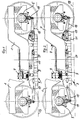
- a bogie frame 1 is a side view Rail vehicle shown, on which an eddy current brake 3 in is arranged in the manner described below.
- the bogie frame 1 one side of the vehicle is resiliently supported on axle bearings 5 of two wheel sets, lifting bellows 7 connected to the bogie frame 1 onto the brake carrier 9 of the eddy current brake 3 act and this from the in Figure 1 shown braking position to raise in the release position shown in Figure 2 assets, as explained below.
- each of the arms 15 is one at its ends Brake carrier provided pivot axis 17, which is outward extending ends of the arms 15 each on a pendulum 19 on the axle bearing 5 are articulated. In this way, the arms 15 and the pendulums 19 are each rotatable about an axis running perpendicular to the image plane; on the opposite The arms 15 act according to FIGS. 3 and 4 with a brake carrier fixed Stop 21 together.
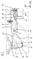
- Figure 3 shows the braking position of the eddy current brake, in which the Stop position of the arm 15 relative to the stop 21 is shown.
- Stop 21 is designed as an eccentric part rotatable about its axis; it other stop elements on which the brake is in are also possible Braking position supports and which are also adjustable to the stop position fixed in height.
- a fork 23 can be provided be used as a side guide for the pivoting movement of the arm 15 encompasses the end about the axis 17, as can be seen from FIGS. 3 and 4 to relieve.
- Vehicle limitation profile with the largest possible width of the magnets from Brake magnet is observed during operation.
- the arm 15 can be pivoted about the position I (axis 17) be, whereby the wheel set change with dismantled pendulum arrangement is hardly hindered.
- the pendulum 19 enables in both positions (braking and releasing position) free movement of the wheel sets in the X direction. Due to the pivoting of the Arms 15 around the axes 17 is in the release position the free deflection of the wheel sets guaranteed. Nevertheless, the brake magnets are in the Y direction constantly (brake and release position) on the axle bearing after the above Led way.
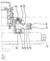
- FIGS. 6-8 of the drawing shown Another embodiment of the suspension is shown in FIGS. 6-8 of the drawing shown.
- the arm is 15 not articulated to the pendulum 19, but is at its end with a spherical support 29 provided in the braking position ( Figure 6) in a pan 31 rests on the underside of the pendulum 19.
- the pendulum is 19 in contrast to the embodiment according to the preceding figures 1-5 as a lever-side open housing is formed, which by the point III extending axis 33 is pivotable. Pins connected to the pendulum 35 are guided in bearings, not explained in detail, which on the Bottom of the axle bearing 5 are provided.
- the arm 15 is in the manner shown in FIG. 7 with the exception of one
- the possibility of changing the position explained below is held in a rotationally fixed manner, i.e. the arm 15 pivots from the transition from the braking position ( Figure 6) in the release position ( Figure 7) no longer around the one running through point I. Axis 17 down, but remains in the horizontal position.
- the end of the arm 15 opposite the support 29 non-rotatable between a spring 37 provided as a stop and a wedge 39 led.
- the wedge 39 with its serving to support the end 41 of the arm 15 Wedge surface 43 is in the illustrated embodiment of a Spindle 45 carried, which e.g. by means of an adjusting hexagon 47 or one comparable device is displaceable in the longitudinal direction, such that a setting explained below, i.e. limited rotation of the lever 15 is possible.
- the arm 15 is only in the braking position ( Figure 6 and 8) with its support 29 in the pan 31 of the pendulum 19.
- the arm 15 has a release position and accordingly the one connected to it Brake in the Y direction between the spaced on the inside of the pendulum Stops 49 against the axle bearing a mutual game, i.e. that in the release position a complete decoupling from the axle bearing is reached.
- the running behavior of the bogie is thus as low as possible Way influenced.
- After releasing the pad 29 from the pan 31 is consequently decoupling in the Z direction (FIG. 7) is also achieved.
- the point of support is Arms on the wedge surface 43 changeable.
- the wedge 39 is over the spindle 45 shifted in the X direction by turning the setting hexagon 47, such that that a limited pivoting of the arm 15 is achieved via the wedge surface 43 is and thus the relative altitude of the pad 29 compared to the Pan 31 can change.
- the arm 15 is non-rotatable in the release and braking positions and the degree of freedom, i.e. the decoupling from the axle bearing through the type of guidance is guaranteed within the pivotable pendulum 19.
- the suspension according to the invention is preferably for use with Eddy current brakes provided, within the scope of the invention In general, it is thought for rail brakes, i.e. magnetic rail brakes and eddy current brakes.
Landscapes
- Physics & Mathematics (AREA)
- Electromagnetism (AREA)
- Engineering & Computer Science (AREA)
- Mechanical Engineering (AREA)
- Braking Arrangements (AREA)
- Vehicle Body Suspensions (AREA)
- Electric Propulsion And Braking For Vehicles (AREA)
- Platform Screen Doors And Railroad Systems (AREA)
Claims (11)
- Suspension d'un frein sur rail, notamment d'un frein à courants de Foucault, à un bogie d'un véhicule sur rails, comportant des châssis de bogie qui s'étendent des deux grands côtés du bogie à partir de celui-ci, et sur lesquels agissent des systèmes de levage qui déplacent le frein sur rail sur des supports de frein, entre la position de freinage abaissée et la position de desserrage relevée, et comportant des guides disposés sur les boítes d'essieu de respectivement deux essieux montés, pour les extrémités frontales des supports de frein du frein sur rail, caractérisée en ce que, comme guides sur les boítes d'essieu (5), il est prévu des pendules (19) articulés sur celles-ci.
- Suspension selon la revendication 1, caractérisée par les caractéristiques suivantes :a) des bras (15) s'étendent depuis les extrémités frontales du support de frein (9) et sont articulés de façon pivotante sur les pendules (19) ;b) les bras sont articulés de façon pivotante sur le support de frein (9) ; etc) il est prévu sur le support de frein des butées (21) pour les bras (15) dans la position abaissée du support de frein.
- Suspension selon la revendication 1, caractérisée par les caractéristiques suivantes :les pendules (19) peuvent se déplacer parallèlement à leur articulation sur la boíte d'essieu (5), entre deux butées, contre un ressort (25) agissant des deux côtés.
- Suspension selon l'une des revendications précédentes, caractérisée par les caractéristiques suivantes :l'un des points de l'articulation du levier (15) sur le support de frein ou sur le pendule (19) est ajustable, afin de pouvoir compenser l'usure du bandage de roue par le moyen de la compensation en hauteur.
- Suspension selon l'une des revendications précédentes, caractérisée en ce que le point de l'articulation du pendule (19) sur la boíte d'essieu (5) et/ou la butée formée pour le levier (15), sur le support de frein est ajustable, afin de pouvoir compenser l'usure du bandage de roue.
- Suspension selon l'une des revendications précédentes, caractérisée en ce que, pour le soutien de la force de freinage, il est prévu au moins une jambe d'appui de frein (27) entre chaque châssis de bogie (1) et le support de frein respectif (9).
- Suspension selon la revendication 6, caractérisée en ce que la jambe d'appui de frein (27) est articulée, de façon pivotante, aussi bien sur le châssis de bogie (1) que sur le support de frein (9).
- Suspension selon la revendication 1, caractérisée par les caractéristiques suivantes :a) depuis les extrémités frontales du support de frein (9) s'étendent des bras (15) guidés rigidement sur celui-cib) les pendules (19) sont réalisés sous la forme de boítiers ouverts en face des bras, qui présentent chacun un coussinet (31) à leur base ;c) les extrémités des bras (15) s'étendent librement à l'intérieur des pendules (19) de telle façon que, dans la position de freinage, elles s'appliquent sur le coussinet (31), par un appui (29) formé à leur extrémité, et que, dans la position de desserrage relevée, elles soient guidées librement, par rapport à des butées (49) formées intérieurement sur le pendule.
- Suspension selon la revendication 8, caractérisée en ce que les bras (15) sont disposés sur le support de frein (9) avec une possibilité de pivotement limité, en vue du rattrapage de l'usure du bandage de roue.
- Suspension selon la revendication 9, caractérisée par les caractéristiques suivantes :a) chaque bras (15) est monté sur le support de frein (9), sur un axe (17) ; etb) l'extrémité (41), opposée à l'appui (29), du bras (15) est bloquée dans les deux sens de rotation entre des butées, dont une est réglable à l'encontre d'une déviation élastique de l'autre.
- Suspension selon la revendication 10, caractérisée par les caractéristiques suivantes :a) l'extrémité (41) du bras (15) s'applique sur la surface en coin (43) d'un coin (39) formant l'une des butées;b) le coin (39) est disposé sur une broche (45) qui est guidée, variable en position sur le support de frein (9) par un moyen de réglage (hexagone de réglage 47) ; etc) l'autre butée est formée par un ressort (37).
Applications Claiming Priority (4)
| Application Number | Priority Date | Filing Date | Title |
|---|---|---|---|
| DE19503387 | 1995-02-02 | ||
| DE19503387 | 1995-02-02 | ||
| DE19530405A DE19530405A1 (de) | 1995-02-02 | 1995-08-18 | Aufhängung einer Schienenbremse, insbesondere Wirbelstrombremse, an einem Drehgestell eines Schienenfahrzeuges |
| DE19530405 | 1995-08-18 |
Publications (2)
| Publication Number | Publication Date |
|---|---|
| EP0724997A1 EP0724997A1 (fr) | 1996-08-07 |
| EP0724997B1 true EP0724997B1 (fr) | 1998-03-18 |
Family
ID=26012084
Family Applications (1)
| Application Number | Title | Priority Date | Filing Date |
|---|---|---|---|
| EP95119534A Expired - Lifetime EP0724997B1 (fr) | 1995-02-02 | 1995-12-12 | Suspension d'un frein sur rail, notamment un frein à courant de Foucault à un bogie de véhicule ferroviaire |
Country Status (3)
| Country | Link |
|---|---|
| EP (1) | EP0724997B1 (fr) |
| AT (1) | ATE164130T1 (fr) |
| ES (1) | ES2113705T3 (fr) |
Cited By (1)
| Publication number | Priority date | Publication date | Assignee | Title |
|---|---|---|---|---|
| CN102556100A (zh) * | 2010-11-22 | 2012-07-11 | 阿尔斯通运输股份有限公司 | 包括涡流制动器装置的铁路车辆转向架 |
Families Citing this family (3)
| Publication number | Priority date | Publication date | Assignee | Title |
|---|---|---|---|---|
| DE19725174C2 (de) * | 1997-06-13 | 1999-08-12 | Knorr Bremse Systeme | Aufhängung einer Schienenbremse an einem Drehgestell eines Schienenfahrzeuges |
| DE19732482A1 (de) * | 1997-07-29 | 1999-02-04 | Sab Wabco Bsi Verkehrstechnik | Magnetische Bremseinrichtung für Schienenfahrzeuge |
| DE102015107346A1 (de) * | 2015-05-11 | 2016-11-17 | Knorr-Bremse Systeme für Schienenfahrzeuge GmbH | Modulare Vorrichtung zum Koppeln eines Magnetsegmentes an zumindest eine Achse eines Schienenfahrzeuges |
Family Cites Families (5)
| Publication number | Priority date | Publication date | Assignee | Title |
|---|---|---|---|---|
| US2180870A (en) * | 1937-10-19 | 1939-11-21 | Westinghouse Air Brake Co | Magnetic rail brake |
| CH242982A (de) * | 1944-10-18 | 1946-06-15 | Bbc Brown Boveri & Cie | Verfahren und Einrichtung zur Vermehrung der Adhäsion bei mit Schienenbremsen ausgerüsteten Triebfahrzeugen. |
| FR1540461A (fr) * | 1967-08-11 | 1968-09-27 | Creusot Forges Ateliers | Dispositif de suspension pendulaire des patins de frein magnétique sur rails, pour bogies de véhicules ferroviaires |
| FR2159772A5 (fr) * | 1971-11-12 | 1973-06-22 | Creusot Loire | |
| FR2314852A1 (fr) | 1975-06-18 | 1977-01-14 | Sncf | Systeme de suspension de frein lineaire a courants de foucault pour vehicule ferroviaire |
-
1995
- 1995-12-12 EP EP95119534A patent/EP0724997B1/fr not_active Expired - Lifetime
- 1995-12-12 AT AT95119534T patent/ATE164130T1/de active
- 1995-12-12 ES ES95119534T patent/ES2113705T3/es not_active Expired - Lifetime
Cited By (2)
| Publication number | Priority date | Publication date | Assignee | Title |
|---|---|---|---|---|
| CN102556100A (zh) * | 2010-11-22 | 2012-07-11 | 阿尔斯通运输股份有限公司 | 包括涡流制动器装置的铁路车辆转向架 |
| CN102556100B (zh) * | 2010-11-22 | 2016-06-01 | 阿尔斯通运输科技公司 | 包括涡流制动器装置的铁路车辆转向架 |
Also Published As
| Publication number | Publication date |
|---|---|
| ES2113705T3 (es) | 1998-05-01 |
| EP0724997A1 (fr) | 1996-08-07 |
| ATE164130T1 (de) | 1998-04-15 |
Similar Documents
| Publication | Publication Date | Title |
|---|---|---|
| DE3111087C2 (de) | Einzelradanordnung für Eisenbahnfahrzeuge | |
| DE3020582C2 (fr) | ||
| CH661014A5 (de) | Laufwerk fuer schienenfahrzeuge. | |
| DE3723833C2 (de) | Radsatzführung für schnellfahrfähige Drehgestelle von Schienenfahrzeugen und Verfahren zum Umrüsten von Drehgestellen auf diese Radsatzführung | |
| DE2255254B2 (de) | Aufhängevorrichtung fur einen Linear Induktor an dem Drehgestell eines Schienenfahrzeugs | |
| WO1998026970A1 (fr) | Chassis de bogie pour materiel ferroviaire roulant | |
| DE2231980C3 (de) | Von einem Linearmotor angetriebenes Schienenfahrzeug | |
| EP2386454B1 (fr) | Bâti tournant | |
| EP0724997B1 (fr) | Suspension d'un frein sur rail, notamment un frein à courant de Foucault à un bogie de véhicule ferroviaire | |
| EP0266374B1 (fr) | Bogie pour vehicules a voie, notamment pour vehicules sur rails | |
| DE19503381C2 (de) | Aufhängung einer Schienenbremse an einem Drehgestell eines Schienenfahrzeuges | |
| DE4242685C2 (de) | Laufwerk für Schienenfahrzeuge | |
| EP0371498B1 (fr) | Connexion entre deux trains de roulement à axes multiples à un groupe de trains de roulement pour véhicules ferroviaires | |
| DE3221755A1 (de) | Drehgestell fuer ein schienenfahrzeug | |
| EP0156143A1 (fr) | Disposition de montage de dispositifs de frein à sabot pour véhicules sur rails | |
| DE19530405A1 (de) | Aufhängung einer Schienenbremse, insbesondere Wirbelstrombremse, an einem Drehgestell eines Schienenfahrzeuges | |
| EP0299318B1 (fr) | Train de roulement pour véhicule ferroviaire avec frein de voie magnétique ou à frein à courants de Foucault | |
| DE10047737A1 (de) | Schienenfahrgerät mit einem Lastträger | |
| DE1913784B2 (de) | Radsatzführung für Schienenfahrzeuge | |
| DE4206342C2 (de) | Scheibenbremsgestänge für Schienenfahrzeuge mit querverschieblichem Radsatz | |
| DE2943014A1 (de) | Schienenfahrzeugfahrgestell | |
| DE3827706A1 (de) | Vierachsiges drehgestell fuer schienenfahrzeuge | |
| DE1096399B (de) | Trennbares, zweiachsiges Drehgestell fuer Schienenfahrzeuge | |
| EP0624506B1 (fr) | Arrangement de leviers pour assemblages de sabot de frein mobiles transversalement pour véhicules ferroviaires | |
| AT394980B (de) | Vierachsiges drehgestell fuer schienenfahrzeuge |
Legal Events
| Date | Code | Title | Description |
|---|---|---|---|
| PUAI | Public reference made under article 153(3) epc to a published international application that has entered the european phase |
Free format text: ORIGINAL CODE: 0009012 |
|
| 17P | Request for examination filed |
Effective date: 19960605 |
|
| AK | Designated contracting states |
Kind code of ref document: A1 Designated state(s): AT CH DE ES FR GB IT LI SE |
|
| GRAG | Despatch of communication of intention to grant |
Free format text: ORIGINAL CODE: EPIDOS AGRA |
|
| GRAG | Despatch of communication of intention to grant |
Free format text: ORIGINAL CODE: EPIDOS AGRA |
|
| GRAH | Despatch of communication of intention to grant a patent |
Free format text: ORIGINAL CODE: EPIDOS IGRA |
|
| 17Q | First examination report despatched |
Effective date: 19970902 |
|
| GRAH | Despatch of communication of intention to grant a patent |
Free format text: ORIGINAL CODE: EPIDOS IGRA |
|
| GRAA | (expected) grant |
Free format text: ORIGINAL CODE: 0009210 |
|
| ITF | It: translation for a ep patent filed |
Owner name: BARZANO' E ZANARDO ROMA S.P.A. |
|
| AK | Designated contracting states |
Kind code of ref document: B1 Designated state(s): AT CH DE ES FR GB IT LI SE |
|
| REF | Corresponds to: |
Ref document number: 164130 Country of ref document: AT Date of ref document: 19980415 Kind code of ref document: T |
|
| REG | Reference to a national code |
Ref country code: CH Ref legal event code: NV Representative=s name: ISLER & PEDRAZZINI AG Ref country code: CH Ref legal event code: EP |
|
| REF | Corresponds to: |
Ref document number: 59501648 Country of ref document: DE Date of ref document: 19980423 |
|
| ET | Fr: translation filed | ||
| REG | Reference to a national code |
Ref country code: ES Ref legal event code: FG2A Ref document number: 2113705 Country of ref document: ES Kind code of ref document: T3 |
|
| GBT | Gb: translation of ep patent filed (gb section 77(6)(a)/1977) |
Effective date: 19980617 |
|
| PLBE | No opposition filed within time limit |
Free format text: ORIGINAL CODE: 0009261 |
|
| STAA | Information on the status of an ep patent application or granted ep patent |
Free format text: STATUS: NO OPPOSITION FILED WITHIN TIME LIMIT |
|
| 26N | No opposition filed | ||
| REG | Reference to a national code |
Ref country code: GB Ref legal event code: IF02 |
|
| PGFP | Annual fee paid to national office [announced via postgrant information from national office to epo] |
Ref country code: GB Payment date: 20021202 Year of fee payment: 8 |
|
| PGFP | Annual fee paid to national office [announced via postgrant information from national office to epo] |
Ref country code: SE Payment date: 20021218 Year of fee payment: 8 |
|
| PG25 | Lapsed in a contracting state [announced via postgrant information from national office to epo] |
Ref country code: GB Free format text: LAPSE BECAUSE OF NON-PAYMENT OF DUE FEES Effective date: 20031212 |
|
| PG25 | Lapsed in a contracting state [announced via postgrant information from national office to epo] |
Ref country code: SE Free format text: LAPSE BECAUSE OF NON-PAYMENT OF DUE FEES Effective date: 20031213 |
|
| EUG | Se: european patent has lapsed | ||
| GBPC | Gb: european patent ceased through non-payment of renewal fee |
Effective date: 20031212 |
|
| REG | Reference to a national code |
Ref country code: CH Ref legal event code: PCAR Free format text: ISLER & PEDRAZZINI AG;POSTFACH 1772;8027 ZUERICH (CH) |
|
| PGFP | Annual fee paid to national office [announced via postgrant information from national office to epo] |
Ref country code: ES Payment date: 20141215 Year of fee payment: 20 Ref country code: DE Payment date: 20141218 Year of fee payment: 20 Ref country code: CH Payment date: 20141216 Year of fee payment: 20 |
|
| PGFP | Annual fee paid to national office [announced via postgrant information from national office to epo] |
Ref country code: AT Payment date: 20141215 Year of fee payment: 20 Ref country code: FR Payment date: 20141212 Year of fee payment: 20 |
|
| PGFP | Annual fee paid to national office [announced via postgrant information from national office to epo] |
Ref country code: IT Payment date: 20141218 Year of fee payment: 20 |
|
| REG | Reference to a national code |
Ref country code: DE Ref legal event code: R071 Ref document number: 59501648 Country of ref document: DE |
|
| REG | Reference to a national code |
Ref country code: CH Ref legal event code: PL |
|
| REG | Reference to a national code |
Ref country code: AT Ref legal event code: MK07 Ref document number: 164130 Country of ref document: AT Kind code of ref document: T Effective date: 20151212 |
|
| REG | Reference to a national code |
Ref country code: ES Ref legal event code: FD2A Effective date: 20160329 |
|
| PG25 | Lapsed in a contracting state [announced via postgrant information from national office to epo] |
Ref country code: ES Free format text: LAPSE BECAUSE OF EXPIRATION OF PROTECTION Effective date: 20151213 |