EP0724995B1 - Verfahren zur raddrehzahlsensorikgestützten, lastadaptiven Einstellung von Bremsdruckregelparametern für die Bremsdruckregelung in einer Fahrzeugbremsanlage - Google Patents
Verfahren zur raddrehzahlsensorikgestützten, lastadaptiven Einstellung von Bremsdruckregelparametern für die Bremsdruckregelung in einer Fahrzeugbremsanlage Download PDFInfo
- Publication number
- EP0724995B1 EP0724995B1 EP19950120110 EP95120110A EP0724995B1 EP 0724995 B1 EP0724995 B1 EP 0724995B1 EP 19950120110 EP19950120110 EP 19950120110 EP 95120110 A EP95120110 A EP 95120110A EP 0724995 B1 EP0724995 B1 EP 0724995B1
- Authority
- EP
- European Patent Office
- Prior art keywords
- brake pressure
- brake
- prescribed
- pressure control
- waiting time
- Prior art date
- Legal status (The legal status is an assumption and is not a legal conclusion. Google has not performed a legal analysis and makes no representation as to the accuracy of the status listed.)
- Expired - Lifetime
Links
- 238000000034 method Methods 0.000 title claims description 32
- 230000003044 adaptive effect Effects 0.000 claims description 2
- 238000012956 testing procedure Methods 0.000 claims 2
- 238000001514 detection method Methods 0.000 description 24
- 238000012360 testing method Methods 0.000 description 11
- 230000005540 biological transmission Effects 0.000 description 5
- 230000004913 activation Effects 0.000 description 4
- 238000011161 development Methods 0.000 description 3
- 230000001419 dependent effect Effects 0.000 description 2
- 230000000694 effects Effects 0.000 description 2
- 238000010998 test method Methods 0.000 description 2
- 238000012795 verification Methods 0.000 description 2
- 230000006978 adaptation Effects 0.000 description 1
- 230000009849 deactivation Effects 0.000 description 1
- 238000001914 filtration Methods 0.000 description 1
- 238000007689 inspection Methods 0.000 description 1
- 238000005259 measurement Methods 0.000 description 1
- 230000007935 neutral effect Effects 0.000 description 1
- 230000001960 triggered effect Effects 0.000 description 1
Images
Classifications
-
- B—PERFORMING OPERATIONS; TRANSPORTING
- B60—VEHICLES IN GENERAL
- B60T—VEHICLE BRAKE CONTROL SYSTEMS OR PARTS THEREOF; BRAKE CONTROL SYSTEMS OR PARTS THEREOF, IN GENERAL; ARRANGEMENT OF BRAKING ELEMENTS ON VEHICLES IN GENERAL; PORTABLE DEVICES FOR PREVENTING UNWANTED MOVEMENT OF VEHICLES; VEHICLE MODIFICATIONS TO FACILITATE COOLING OF BRAKES
- B60T8/00—Arrangements for adjusting wheel-braking force to meet varying vehicular or ground-surface conditions, e.g. limiting or varying distribution of braking force
- B60T8/32—Arrangements for adjusting wheel-braking force to meet varying vehicular or ground-surface conditions, e.g. limiting or varying distribution of braking force responsive to a speed condition, e.g. acceleration or deceleration
- B60T8/34—Arrangements for adjusting wheel-braking force to meet varying vehicular or ground-surface conditions, e.g. limiting or varying distribution of braking force responsive to a speed condition, e.g. acceleration or deceleration having a fluid pressure regulator responsive to a speed condition
- B60T8/48—Arrangements for adjusting wheel-braking force to meet varying vehicular or ground-surface conditions, e.g. limiting or varying distribution of braking force responsive to a speed condition, e.g. acceleration or deceleration having a fluid pressure regulator responsive to a speed condition connecting the brake actuator to an alternative or additional source of fluid pressure, e.g. traction control systems
-
- B—PERFORMING OPERATIONS; TRANSPORTING
- B60—VEHICLES IN GENERAL
- B60T—VEHICLE BRAKE CONTROL SYSTEMS OR PARTS THEREOF; BRAKE CONTROL SYSTEMS OR PARTS THEREOF, IN GENERAL; ARRANGEMENT OF BRAKING ELEMENTS ON VEHICLES IN GENERAL; PORTABLE DEVICES FOR PREVENTING UNWANTED MOVEMENT OF VEHICLES; VEHICLE MODIFICATIONS TO FACILITATE COOLING OF BRAKES
- B60T8/00—Arrangements for adjusting wheel-braking force to meet varying vehicular or ground-surface conditions, e.g. limiting or varying distribution of braking force
- B60T8/17—Using electrical or electronic regulation means to control braking
- B60T8/172—Determining control parameters used in the regulation, e.g. by calculations involving measured or detected parameters
-
- B—PERFORMING OPERATIONS; TRANSPORTING
- B60—VEHICLES IN GENERAL
- B60T—VEHICLE BRAKE CONTROL SYSTEMS OR PARTS THEREOF; BRAKE CONTROL SYSTEMS OR PARTS THEREOF, IN GENERAL; ARRANGEMENT OF BRAKING ELEMENTS ON VEHICLES IN GENERAL; PORTABLE DEVICES FOR PREVENTING UNWANTED MOVEMENT OF VEHICLES; VEHICLE MODIFICATIONS TO FACILITATE COOLING OF BRAKES
- B60T8/00—Arrangements for adjusting wheel-braking force to meet varying vehicular or ground-surface conditions, e.g. limiting or varying distribution of braking force
- B60T8/17—Using electrical or electronic regulation means to control braking
- B60T8/176—Brake regulation specially adapted to prevent excessive wheel slip during vehicle deceleration, e.g. ABS
- B60T8/1766—Proportioning of brake forces according to vehicle axle loads, e.g. front to rear of vehicle
-
- B—PERFORMING OPERATIONS; TRANSPORTING
- B60—VEHICLES IN GENERAL
- B60T—VEHICLE BRAKE CONTROL SYSTEMS OR PARTS THEREOF; BRAKE CONTROL SYSTEMS OR PARTS THEREOF, IN GENERAL; ARRANGEMENT OF BRAKING ELEMENTS ON VEHICLES IN GENERAL; PORTABLE DEVICES FOR PREVENTING UNWANTED MOVEMENT OF VEHICLES; VEHICLE MODIFICATIONS TO FACILITATE COOLING OF BRAKES
- B60T8/00—Arrangements for adjusting wheel-braking force to meet varying vehicular or ground-surface conditions, e.g. limiting or varying distribution of braking force
- B60T8/18—Arrangements for adjusting wheel-braking force to meet varying vehicular or ground-surface conditions, e.g. limiting or varying distribution of braking force responsive to vehicle weight or load, e.g. load distribution
- B60T8/1806—Arrangements for adjusting wheel-braking force to meet varying vehicular or ground-surface conditions, e.g. limiting or varying distribution of braking force responsive to vehicle weight or load, e.g. load distribution characterised by the calibration process or the means therefor
Definitions
- the invention relates to a method for wheel speed sensor-based, load-adaptive setting of brake pressure control parameters for brake pressure control in a vehicle brake system.
- a method for wheel speed sensor-based, load-adaptive setting of brake pressure control parameters for brake pressure control in a vehicle brake system is known from DE 40 07 360 A1 or also known from DE 38 29 951 C1.
- the wheel speed information is usually in the form so-called wheel speeds, i.e. the product of wheel speed and wheel circumference, processed.
- the wheel speed information can, for example, with a suitable analysis to determine the Loading state are used, so that a loading sensor system is unnecessary. It can also be the distribution of Brake pressure on the various vehicle axles and / or that Ratio of total brake pressure to that caused by the brake pedal position certain vehicle target deceleration of start values adapt automatically to the respective load condition based on this.
- the braking system function also with regard to the provision the maximum brake pressure on a respective wheel, e.g. for diagnostic purposes or to check the achievable braking forces on a roller dynamometer.
- the load-dependent Brake pressure control parameters generally values, by which not even with a full braking request maximum brake pressure for each brake system that can be braked Wheel is set, e.g. with unequal brake pressure distribution on the different vehicle axles or at the moment low set ratio of total brake pressure to vehicle target deceleration due to a low vehicle load.
- ASR Traction control system
- the invention is a technical problem of providing based on a method with which vehicle brake systems load-adaptive, wheel speed sensor-based brake pressure control if necessary also with regard to the control of the maximum of brake pressure that can be generated by the brake system can be checked.
- this low limit speed which is typical is at most between 1km / h and 3km / h, as well as the Ensure that the waiting time is set, typically between 3s and 5s the reliable detection of one for checking the Braking system ready vehicle by means of the system Sufficiently plausible measurement signals from the wheel speed sensor system.
- This Condition also allows the brake system to be unique to recognize that for a subsequent full braking request the setting of the maximum brake pressure is desired. If the condition is not met, the brake system sets the belonging to the current brake pressure control parameter values, load-adapted brake pressure, and that directly after one Vehicle start when the test process is stopped Brake pressure that corresponds to the start values of the brake pressure control parameters heard. Consequently, the procedure can be broken this waiting time also the adjustment of the load adaptive Check the brake pressure values by the brake system.
- a development of the invention according to claim 3 provides for a braking system with ASR to keep the ASR function deactivated, when the system detects that the transmission is in neutral located. This ensures in a simple manner that the ASR function is not inadvertently during a check the brake system activated on a roller dynamometer becomes. To implement this measure, the brake system controller receives a corresponding transmission position signal from the transmission control.
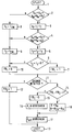
- the single figure shows a program flow chart of a method for checking a vehicle brake system with load-adaptive, Wheel speed sensor-assisted brake pressure control for the Wheels of two axles.
- the process sequence shown in the figure is run through cyclically with a predetermined cycle time (t T ).
- initial values for required parameters are set, in the present example 0s for a first waiting time count (t 1 ), 5s for a second waiting time count (t 2 ), the value zero for a speed condition Detection bit (FB 1 ) and the value one for a brake start detection bit (FB 2 ).
- a first waiting time (t 1W ) is set at 20s
- a second waiting time (t 2W ) at 5s
- a first limit speed (v 1 ) at 12 km / h
- a second limit speed (v 2 ) at 1 km / h.
- Each process cycle begins with a start step (1), which is followed by a query step (2), in which it is determined whether the wheel speeds of the front left wheel (v vl ), the front right wheel (v vr ), the rear left wheel (v hl ) and the rear right wheel (v hr ) are all less than the first limit speed (v 1 ) of 12 km / h.
- These wheel speeds (v vl , v vr , v hl , v hr ) are the speed values obtained from a conventional wheel speed sensor system of a wheel slip control system and subjected to filtering.
- the cycle time (t T ) is subtracted from the first waiting time count (t 1 ) (step 3), the first waiting time count (t 1 ) remaining limited to at least zero.
- a second wheel speed query step (4) in which it is determined whether the two wheel speeds (v vl , v vr ) of the front axle wheels or the two wheel speeds (v hl , v hr ) of the rear axle wheels are lower than the second limit speed (v 2 ) of 1km / h. If so, then the second Wartezeitgeber (t 2) also to the cycle time (t T) is lowered (step 5), whereby this count is (t 2) down to zero restricted.
- a subsequent query step (6) it is now determined whether the two waiting time counts (t 1 , t 2 ) are both zero. If so, the speed condition detection bit (FB 1 ) is set to one (step 7), while it is otherwise set to zero (step 10). If it was determined in the second speed query step (4) that the wheel speeds of the two respective wheels are not below the second limit speed (v 2 ) of 1 km / h for either the front or the rear axle, then the second waiting time count (t 2 ) set to the second waiting period (t 2W ) (step 9), after which the speed condition detection bit (FB 1 ) is again set to zero (step 10).
- the first speed query step (2) If it has been determined in the first speed query step (2) that at least one of the four wheel speeds (v vl , v vr , v hl , v hr ) is at or above the first limit speed (v 1 ) of 12 km / h, then the first becomes Waiting time count (t 1 ) is set to the first waiting period (t 1W ) (step 8), after which, as if the second speed query (4) is negated, the second waiting count (t 2 ) for the second waiting period (t 2W ) and the speed condition detection bit ( FB 1 ) are set to zero (steps 9 and 10).
- step (11) it is determined whether the brake system is currently actuated. If this is not the case, the brake start detection bit (FB 2 ) is set to one (step 12), after which the process jumps to the end (13) of a process cycle. If, on the other hand, the presence of a brake application is ascertained, the next step is to query (step 14) whether both the speed condition detection bit (FB 1 ) and the start of braking detection bit (FB 2 ) have the value one.
- the brake start detection bit (FB 2 ) is set to zero (step 15), and then the brake pressure distribution ( ⁇ ) and the total brake pressure / target deceleration ratio ( ⁇ ) are adapted as the relevant brake pressure control parameters to the current vehicle load condition recalculated (step 16). With these current load-adapted values of the brake pressure control parameters ( ⁇ , ⁇ ), the target brake pressures (p soll ) for the vehicle wheels influenced by the brake system are then calculated (step 17), after which the end of the cycle (13) is reached again.
- step 17 The target braking pressures with the thus set brake pressure control parameter values again (p set) is calculated (step 17), with the result that now all the wheels are subjected to the maximum brake pressure of the brake system. After the target brake pressure calculation, the end of the cycle (13) is reached again.
- the detection bit query step (14) decides whether the maximum brake pressure is provided independently of the load when a brake is actuated for checking the brake system or whether the brake pressure control parameters are updated depending on the load and the target brake pressures adjusted to the current load conditions are set.
- the former is the case if both detection bits (FB 1 , FB 2 ) have the value one. This makes it possible to check the brake system both with load-adaptive brake pressure setting and at any time with regard to its function at maximum brake pressure.
- the speed condition detection bit (FB 1 ) represents compliance with the speed conditions, as can be seen from the first half of the process cycle.
- the first speed query block determines whether all wheel speeds are below 12 km / h for a sufficiently long time. This enables the system to differentiate between a brake system test procedure with the desired maximum brake pressure and braking in quick succession while driving.
- no corresponding waiting time takes effect because of the first waiting time count (t 1 ) initially set to zero.
- the speed condition detection bit (FB 1 ) Since the associated second waiting time count (t 2 ) is already set to the second waiting time (t 2W ) of 5s when the vehicle or the brake system control is started and the speed condition detection bit (FB 1 ) only assumes the value one if both waiting time counts (t 1 , t 2 ) have reached the value zero, it is always a prerequisite for checking the brake system at maximum brake pressure that the wheel speeds of the wheels on an axle are below 1 km / h for at least 5s. This reliably detects a test situation when the vehicle is stationary, which allows the generation of the maximum brake pressure. For example, if the vehicle is driven by the wheels of one axle from the rollers of a roller dynamometer for brake system testing purposes, the wheels of the other axle stand still so that this speed condition is met.
- the brake start detection bit (FB 2 ) has the effect that the above speed conditions must have existed since the respective waiting times in relation to the start of a brake application. As soon as a brake application has been recognized, but the two detection bits (FB 1 , FB 2 ) are not both on one, the start of braking detection bit (FB 2 ) is set to zero and remains at this value until a missing cycle occurs again in a later cycle Brake application was recognized. The subsequent return of the brake start detection bit (FB 2 ) to the value one then enables a brake system test to be carried out at maximum brake pressure as soon as the speed conditions are also present.
- the following functions of the vehicle brake system can thus be checked by the described method. If the check is carried out immediately after starting the vehicle from standstill or equivalent to starting the brake system control without the second waiting time (t 2W ) from 5s to the brake application being maintained, the brake system sets the target brake pressures according to the stored initial values for the Brake pressure control parameters ( ⁇ , ⁇ ), because in this case there has been no braking process since the vehicle was started, which would have led to the load-dependent adaptation of these brake pressure control parameters. Accordingly, the brake pressure profiles can be checked in accordance with the starting values of the brake pressure control parameters using this procedure.
- the setting of the maximum brake pressure e.g. 10bar
- the setting of the maximum brake pressure can be checked on all affected wheels.
- it can be checked whether the prescribed timing behavior is adhered to at the predetermined brake pedal actuation speed.
- a check of the brake system when the load is adjusted Brake pressure can be made by first with the vehicle a normal driving operation with several braking operations load-adaptive setting of the brake pressure control parameters ( ⁇ , ⁇ ) carried out and then the vehicle to a standstill is braked without the two speed conditions, i.e. all wheel speeds below 12km / h for at least 20s and the wheel speeds on an axle under 1km / h for at least 5s to be observed.
- the Brake system can then be checked according to the brake pressure setpoints the load-adapted brake pressure control parameters. If so then the brakes released and the speed conditions are observed during the required waiting times, is the verification of the after a new brake application Brake system in turn at maximum brake pressure on all wheels possible.
- the above mode of operation when driving can alternatively to one simulated actual driving on a roller dynamometer will.
- the braking forces can be adjusted according to the load-adaptive brake pressure control parameter values be checked if the brake is not or is only briefly solved, so that the speed conditions are not adhered to. Then when the brake is solved and the speed conditions during the given Waiting times can be observed after a brake again by setting the maximum Check the braking pressure of the maximum achievable braking forces.
- Preventing vehicle does not include the procedure in the ability to perform the ASR function during to keep such a test process deactivated. This will be a Activation of the ASR function prevented as long as the vehicle transmission is in the idle position, as with a such test procedure is the case.
- This information is the Brake system control from a transmission control of the vehicle transmitted.
- the ASR function can be used during test processes the brake system is deactivated on a roller dynamometer be held that such a dynamometer operation directly from the ASR control unit by requesting one when the dynamometer operation is active set dynamometer detection bits or through a query about compliance with the above Speed conditions for the release of the maximum Brake pressure is recognized.
- a corresponding cancellation signal that e.g. in the detection of the operation of the accelerator pedal or the clutch pedal can be generated, this can Deactivation function for the respective wheel slip control system be canceled again.
- the method described above thus enables verification a braking system with load-adaptive, wheel speed sensor-based Brake pressure control and not with a wheel slip control system only under the conditions of load adaptively adjusted brake pressures, but also with regard to the function at maximum brake pressure, the control of the maximum brake pressure by the system automatically in the presence of suitable vehicle condition conditions regardless of the current load status and without interference a possible traction control carried out becomes.
Landscapes
- Engineering & Computer Science (AREA)
- Transportation (AREA)
- Mechanical Engineering (AREA)
- Physics & Mathematics (AREA)
- Fluid Mechanics (AREA)
- Regulating Braking Force (AREA)
Description
Claims (4)
- Verfahren zur raddrehzahlsensorikgestützten, lastadaptiven Einstellung von Bremsdruckregelparametern für die Bremsdruckregelung in einer Fahrzeugbremsanlage,
dadurch gekennzeichnet, daßdie Bremsdruckregelparameter (κ, ) während eines Bremsanlagen-Prüfvorgangs bei Einhaltung mindestens einer vorgegebenen Fahrzustandsbedingung selbsttätig auf maximalen Bremsdruck erzeugende Werte eingestellt werden, wobeieine vorgegebene Fahrzustandsbedingung darin besteht, daß bei Bremsbeginn die Radgeschwindigkeiten der Räder wenigstens einer Achse (vvl, vvr; vhl, vhr) seit einer vorgegebenen Wartezeit (t2W) kleiner als eine vorgegebene Grenzgeschwindigkeit (v2) sind, die höchstens geringfügig größer als null ist. - Verfahren nach Anspruch 1,
dadurch gekennzeichnet, daß
eine weitere vorgegebene Fahrzustandsbedingung zur Einstellung des maximalen Bremsdrucks während eines Prüfvorgangs darin besteht, daß bei Bremsbeginn die Radgeschwindigkeiten aller Räder (vvl, vvr, vhl, vhr) direkt nach einem Start des Fahrzeugs oder der Bremsanlagensteuerung oder seit einer vorgegebenen weiteren Wartezeit (t1W) kleiner als eine vorgegebene weitere Grenzgeschwindigkeit (v1) sind. - Verfahren nach Anspruch 1 oder 2,
dadurch gekennzeichnet, daß
für eine Bremsanlage mit Antriebsschlupfregelung (ASR) die ASR-Funktion deaktiviert gehalten wird, solange sich das Getriebe des Fahrzeugs in Leerlaufstellung befindet. - Verfahren nach Anspruch 1 oder 2,
dadurch gekennzeichnet, daß
für eine Bremsanlage mit Antriebsschlupfregelung (ASR) die ASR-Funktion deaktiviert gehalten wird, wenn ein Rollenprüfstandsbetrieb dadurch erkannt wird, daß der ASR-Steuerung ein Rollenprüfstandsbetrieb-Erkennungsbit oder eine Information darüber, daß bei Bremsbeginn die Radgeschwindigkeiten der Räder wenigstens einer Achse (vvl, vvr; vhl, vhr) seit einer vorgegebenen Wartezeit (t2W) kleiner als eine vorgegebene Grenzgeschwindigkeit (v2) sind, die höchstens geringfügig größer als null ist, und die Radgeschwindigkeiten aller Räder (vvl, vvr, vhl, vhr) seit einer vorgegebenen weiteren Wartezeit (t1W) kleiner als eine vorgegebene weitere Grenzgeschwindigkeit (v1) sind, zugeführt wird.
Applications Claiming Priority (2)
| Application Number | Priority Date | Filing Date | Title |
|---|---|---|---|
| DE19503455 | 1995-02-03 | ||
| DE1995103455 DE19503455C1 (de) | 1995-02-03 | 1995-02-03 | Verfahren zur raddrehzahlsensorikgestützten, lastadaptiven Einstellung von Bremsdruckregelparametern für die Bremsdruckregelung in einer Fahrzeugbremsanlage |
Publications (2)
| Publication Number | Publication Date |
|---|---|
| EP0724995A1 EP0724995A1 (de) | 1996-08-07 |
| EP0724995B1 true EP0724995B1 (de) | 1998-05-20 |
Family
ID=7753046
Family Applications (1)
| Application Number | Title | Priority Date | Filing Date |
|---|---|---|---|
| EP19950120110 Expired - Lifetime EP0724995B1 (de) | 1995-02-03 | 1995-12-19 | Verfahren zur raddrehzahlsensorikgestützten, lastadaptiven Einstellung von Bremsdruckregelparametern für die Bremsdruckregelung in einer Fahrzeugbremsanlage |
Country Status (2)
| Country | Link |
|---|---|
| EP (1) | EP0724995B1 (de) |
| DE (1) | DE19503455C1 (de) |
Families Citing this family (2)
| Publication number | Priority date | Publication date | Assignee | Title |
|---|---|---|---|---|
| DE10232792A1 (de) | 2002-07-19 | 2004-02-12 | Wabco Gmbh & Co. Ohg | Bremsverfahren für ein Fahrzeug |
| CN116642710B (zh) * | 2023-05-26 | 2026-01-30 | 东风汽车有限公司东风日产乘用车公司 | 制动液压限值调整方法、装置、设备及存储介质 |
Family Cites Families (2)
| Publication number | Priority date | Publication date | Assignee | Title |
|---|---|---|---|---|
| DE3432841A1 (de) * | 1984-09-07 | 1986-03-20 | Robert Bosch Gmbh, 7000 Stuttgart | Bremskraftregelanlage |
| DE4007360A1 (de) * | 1990-03-08 | 1991-09-12 | Daimler Benz Ag | Verfahren zur bremsdruckverteilung auf die achsen eines kraftfahrzeugs mit abs-druckmittelbremse |
-
1995
- 1995-02-03 DE DE1995103455 patent/DE19503455C1/de not_active Expired - Lifetime
- 1995-12-19 EP EP19950120110 patent/EP0724995B1/de not_active Expired - Lifetime
Also Published As
| Publication number | Publication date |
|---|---|
| DE19503455C1 (de) | 1996-03-21 |
| EP0724995A1 (de) | 1996-08-07 |
Similar Documents
| Publication | Publication Date | Title |
|---|---|---|
| DE19503451C1 (de) | Verfahren zur Überprüfung der Bremsanlage eines Fahrzeugs | |
| DE69913406T2 (de) | Vorrichtung zur Verhaltenssteuerung eines Kraftfahrzeuges mit Hilfe der Bremsen | |
| DE4011272C2 (de) | Vorrichtung zum Steuern der Verteilung des Antriebsmomentes bei einem Fahrzeug mit Vierradantrieb | |
| DE4438017C2 (de) | Verfahren und Vorrichtung zur elektrischen Steuerung bzw. Regelung der Bremsanlage eines Fahrzeugs | |
| EP3625094B1 (de) | Verfahren zur schätzung der erreichbaren gesamtbremskräfte zur automatisierten verzögerung eines nutzfahrzeugs, bremsanlage sowie nutzfahrzeug damit | |
| EP0497095A2 (de) | Verfahren zur Anpassung von Schlupfschwellenwerten für ein Antriebs-Schlupf- und/oder ein Bremsschlupf-Regelsystem an die Bereifung eines Kraftfahrzeuges sowie Einrichtung zur Durchführung des Verfahrens | |
| DE4011214A1 (de) | Steuereinrichtung zur verteilung der antriebskraft fuer ein kraftfahrzeug | |
| DE69210840T2 (de) | Bremsverteilungssystem mit hintergrundsbremsmöglichkeit für ein fahrzeug mit vielen achsen | |
| DE112016002738T5 (de) | System und Verfahren zur Begrenzung regenerativen Bremsens | |
| WO2018192738A1 (de) | Verfahren zum überwachen einer umsetzung einer automatisiert angeforderten bremsvorgabe sowie bremssystem | |
| DE102007045998A1 (de) | Technik zur Verbesserung der Fahrstabilität eines Kraftfahrzeugs auf Basis einer Massebestimmung | |
| DE4114047A1 (de) | Elektronisches brems- oder anfahrregelsystem fuer fahrzeuge | |
| DE19521872B4 (de) | Verfahren zur Steuerung der Bremsanlage eines Fahrzeugs | |
| EP1200294B1 (de) | Verfahren zur funktionsprüfung einer fahrdynamikregelungssensorik | |
| DE19844542A1 (de) | Vorrichtung und Verfahren zum Begrenzen einer Rückrollgeschwindigkeit eines Kraftfahrzeuges | |
| DE102004030795B4 (de) | Rückrollbegrenzung für ein Kraftfahrzeug | |
| EP0827859A2 (de) | Verfahren und Vorrichtung zur Verbesserung der Fahrstabilität im Schubbetrieb | |
| DE69016282T2 (de) | Antiblockier-Bremssteuerungssystem (ABS). | |
| EP0927119B1 (de) | Verfahren und vorrichtung zur ermittlung einer die fahrzeuggeschwindigkeit beschreibenden grösse | |
| EP0844954B1 (de) | Verfahren und vorrichtung zur steuerung der bremsanlage eines fahrzeugs | |
| DE10065759A1 (de) | Vorrichtung und Verfahren zur Überwachung eines Drucksensors | |
| EP0969994B1 (de) | Verfahren und vorrichtung zur ermittlung einer die fahrzeuggeschwindigkeit beschreibenden grösse | |
| DE19647436C2 (de) | Steuereinrichtung zum Überwachen der Bremsanlage eines Kraftfahrzeuges | |
| EP0724995B1 (de) | Verfahren zur raddrehzahlsensorikgestützten, lastadaptiven Einstellung von Bremsdruckregelparametern für die Bremsdruckregelung in einer Fahrzeugbremsanlage | |
| DE69201791T2 (de) | Bremsen mit verzögerungssteuerung. |
Legal Events
| Date | Code | Title | Description |
|---|---|---|---|
| PUAI | Public reference made under article 153(3) epc to a published international application that has entered the european phase |
Free format text: ORIGINAL CODE: 0009012 |
|
| 17P | Request for examination filed |
Effective date: 19960605 |
|
| AK | Designated contracting states |
Kind code of ref document: A1 Designated state(s): FR GB IT NL SE |
|
| 17Q | First examination report despatched |
Effective date: 19970527 |
|
| RAP1 | Party data changed (applicant data changed or rights of an application transferred) |
Owner name: DAIMLER-BENZ AKTIENGESELLSCHAFT |
|
| GRAG | Despatch of communication of intention to grant |
Free format text: ORIGINAL CODE: EPIDOS AGRA |
|
| GRAG | Despatch of communication of intention to grant |
Free format text: ORIGINAL CODE: EPIDOS AGRA |
|
| GRAH | Despatch of communication of intention to grant a patent |
Free format text: ORIGINAL CODE: EPIDOS IGRA |
|
| GRAH | Despatch of communication of intention to grant a patent |
Free format text: ORIGINAL CODE: EPIDOS IGRA |
|
| GRAA | (expected) grant |
Free format text: ORIGINAL CODE: 0009210 |
|
| ITF | It: translation for a ep patent filed | ||
| AK | Designated contracting states |
Kind code of ref document: B1 Designated state(s): FR GB IT NL SE |
|
| GBT | Gb: translation of ep patent filed (gb section 77(6)(a)/1977) |
Effective date: 19980528 |
|
| ET | Fr: translation filed | ||
| PLBE | No opposition filed within time limit |
Free format text: ORIGINAL CODE: 0009261 |
|
| STAA | Information on the status of an ep patent application or granted ep patent |
Free format text: STATUS: NO OPPOSITION FILED WITHIN TIME LIMIT |
|
| RAP2 | Party data changed (patent owner data changed or rights of a patent transferred) |
Owner name: DAIMLERCHRYSLER AG |
|
| 26N | No opposition filed | ||
| NLT2 | Nl: modifications (of names), taken from the european patent patent bulletin |
Owner name: DAIMLERCHRYSLER AG |
|
| REG | Reference to a national code |
Ref country code: GB Ref legal event code: IF02 |
|
| NLS | Nl: assignments of ep-patents |
Owner name: DAIMLERCHRYSLER AG Effective date: 20080402 |
|
| NLT1 | Nl: modifications of names registered in virtue of documents presented to the patent office pursuant to art. 16 a, paragraph 1 |
Owner name: DAIMLER AG |
|
| REG | Reference to a national code |
Ref country code: FR Ref legal event code: CD Ref country code: FR Ref legal event code: CA |
|
| REG | Reference to a national code |
Ref country code: NL Ref legal event code: SD Effective date: 20101102 |
|
| REG | Reference to a national code |
Ref country code: FR Ref legal event code: TP |
|
| PGFP | Annual fee paid to national office [announced via postgrant information from national office to epo] |
Ref country code: GB Payment date: 20131217 Year of fee payment: 19 |
|
| PGFP | Annual fee paid to national office [announced via postgrant information from national office to epo] |
Ref country code: SE Payment date: 20141216 Year of fee payment: 20 |
|
| PGFP | Annual fee paid to national office [announced via postgrant information from national office to epo] |
Ref country code: FR Payment date: 20141212 Year of fee payment: 20 Ref country code: NL Payment date: 20141215 Year of fee payment: 20 |
|
| PGFP | Annual fee paid to national office [announced via postgrant information from national office to epo] |
Ref country code: IT Payment date: 20141216 Year of fee payment: 20 |
|
| GBPC | Gb: european patent ceased through non-payment of renewal fee |
Effective date: 20141219 |
|
| PG25 | Lapsed in a contracting state [announced via postgrant information from national office to epo] |
Ref country code: GB Free format text: LAPSE BECAUSE OF NON-PAYMENT OF DUE FEES Effective date: 20141219 |
|
| REG | Reference to a national code |
Ref country code: NL Ref legal event code: MK Effective date: 20151218 |
|
| REG | Reference to a national code |
Ref country code: SE Ref legal event code: EUG |