EP0723381B2 - Dispositif d'assistance auditive - Google Patents
Dispositif d'assistance auditive Download PDFInfo
- Publication number
- EP0723381B2 EP0723381B2 EP94120781A EP94120781A EP0723381B2 EP 0723381 B2 EP0723381 B2 EP 0723381B2 EP 94120781 A EP94120781 A EP 94120781A EP 94120781 A EP94120781 A EP 94120781A EP 0723381 B2 EP0723381 B2 EP 0723381B2
- Authority
- EP
- European Patent Office
- Prior art keywords
- control unit
- ear
- region
- microphones
- area
- Prior art date
- Legal status (The legal status is an assumption and is not a legal conclusion. Google has not performed a legal analysis and makes no representation as to the accuracy of the status listed.)
- Expired - Lifetime
Links
Images


Classifications
-
- H—ELECTRICITY
- H04—ELECTRIC COMMUNICATION TECHNIQUE
- H04R—LOUDSPEAKERS, MICROPHONES, GRAMOPHONE PICK-UPS OR LIKE ACOUSTIC ELECTROMECHANICAL TRANSDUCERS; DEAF-AID SETS; PUBLIC ADDRESS SYSTEMS
- H04R25/00—Deaf-aid sets, i.e. electro-acoustic or electro-mechanical hearing aids; Electric tinnitus maskers providing an auditory perception
- H04R25/04—Deaf-aid sets, i.e. electro-acoustic or electro-mechanical hearing aids; Electric tinnitus maskers providing an auditory perception comprising pocket amplifiers
-
- H—ELECTRICITY
- H04—ELECTRIC COMMUNICATION TECHNIQUE
- H04R—LOUDSPEAKERS, MICROPHONES, GRAMOPHONE PICK-UPS OR LIKE ACOUSTIC ELECTROMECHANICAL TRANSDUCERS; DEAF-AID SETS; PUBLIC ADDRESS SYSTEMS
- H04R25/00—Deaf-aid sets, i.e. electro-acoustic or electro-mechanical hearing aids; Electric tinnitus maskers providing an auditory perception
- H04R25/55—Deaf-aid sets, i.e. electro-acoustic or electro-mechanical hearing aids; Electric tinnitus maskers providing an auditory perception using an external connection, either wireless or wired
- H04R25/552—Binaural
-
- H—ELECTRICITY
- H04—ELECTRIC COMMUNICATION TECHNIQUE
- H04R—LOUDSPEAKERS, MICROPHONES, GRAMOPHONE PICK-UPS OR LIKE ACOUSTIC ELECTROMECHANICAL TRANSDUCERS; DEAF-AID SETS; PUBLIC ADDRESS SYSTEMS
- H04R25/00—Deaf-aid sets, i.e. electro-acoustic or electro-mechanical hearing aids; Electric tinnitus maskers providing an auditory perception
- H04R25/40—Arrangements for obtaining a desired directivity characteristic
- H04R25/407—Circuits for combining signals of a plurality of transducers
-
- H—ELECTRICITY
- H04—ELECTRIC COMMUNICATION TECHNIQUE
- H04R—LOUDSPEAKERS, MICROPHONES, GRAMOPHONE PICK-UPS OR LIKE ACOUSTIC ELECTROMECHANICAL TRANSDUCERS; DEAF-AID SETS; PUBLIC ADDRESS SYSTEMS
- H04R25/00—Deaf-aid sets, i.e. electro-acoustic or electro-mechanical hearing aids; Electric tinnitus maskers providing an auditory perception
- H04R25/60—Mounting or interconnection of hearing aid parts, e.g. inside tips, housings or to ossicles
- H04R25/602—Mounting or interconnection of hearing aid parts, e.g. inside tips, housings or to ossicles of batteries
Definitions
- the invention relates to a device for hearing support, which has two microphones with one Control unit are coupled and the control unit with Feed input signals and at which the control unit at least one output signal to at least one Transmission element transmitted and at which the control unit spatially separated from the microphones is, as well as with the microphones in the area of a human ear can be arranged in ear housings are recorded and in which the ear housings each are provided with a transmitter with a receiver communicates in the area of the control unit, and in the area of at least one of the ear housings one of the transmission elements is arranged, the is provided with a receiver with a transmitter communicates in the area of the control unit as well with an analyzer in the area of the control unit Evaluation of the signals of the microphones is arranged.
- a device is already known from FR-A-2 651 634 known for hearing support, in which a microphone with a control unit is coupled and in which the control unit spatially separated from the microphone is.
- the microphone is in the area of an ear casing arranged that is recordable by a human ear is. Communication takes place via a Receiver and a transmitter and in the area of the control unit is an analyzer for evaluating the signals arranged the microphone.
- DE-A-2 406 218 discloses a device for Hearing support is described with two microphones be used. However, both microphones are arranged in a common ear housing. At least one of the microphones has a directional characteristic on. The signals from the two microphones are in the Processed area of a control unit.
- a microphone is printed in the area of an ear housing arranged, which is arranged with a spatially separate Control unit Via one transmitter and one Receiver communicates.
- a comparable device is from DE-OS 35 12 999 known. Through a different orientation of the microphones and a subsequent subtraction the output signals of the microphones from each other it should enable one in all listening directions to eliminate effective ambient noise.
- the Transmission element is designed here as a loudspeaker.
- DE-OS 35 08 830 it is known locally separated from a speaker in an ear case is arranged, which in turn by one human ear recordable or behind can be arranged in a human ear, in the area of a separate control unit, a microphone, an amplifier and arrange a power source.
- a wireless transmission of signals to one Hearing aid is described in DE-OS 30 32 311.
- signals to be transmitted wirelessly for example from a telecommunications system or provided a radio become.
- Another construction in which a spatial Separation of loudspeaker and control unit provided is described in DE-OS 28 44 979.
- the microphone is also in the area of the control unit arranged.
- DE 31 00 135 C2 is already a device known for hearing support, the two microphones has, which are coupled to a control unit.
- the Microphones feed the control unit with input signals.
- the control unit transmits at least one output signal to at least one transmission element.
- the control unit is spatially separated from the Microphones arranged and each of the microphones is from accommodated in a housing.
- One of the transmission elements is arranged in the area of an ear housing.
- There is a comparator in the area of the control unit provided for evaluating the signals of the microphones, which is the output power of the control unit Modification adapted to sound reproduction.
- DE 30 27 384 describes a method for forming described by sound signals, in which the unnatural Directional sensations through the forming regarding the directional impressions in the natural Hearing sensations better approximated hearing sensations can be converted.
- DE 41 01 933 A 1 describes a control unit for directional microphone signals for the generation of virtual Directional characteristics with adjustable main reception direction.
- the output signal is multiplied by Evaluation of the input signals with control parameters educated.
- DE 35 30 205 Al already has a microphone system known with variable directional characteristic, the one Row of microphones that are equidistant are arranged to each other.
- the directional pattern is due to a special row-like arrangement of the microphones and by using a weighting network realized with weighting factors.
- DE 29 28 845 A1 describes an audiovocal integration device described, which has a microphone, that through a special device with a vibrator is coupled, the vibrations on the skin of a user can muster. About a corresponding one Control takes place a coordination of the acoustic as well as the sensitive signal transmission.
- Devices for hearing support are known at which all components in the field of human Arranged ear, or in which at one spatial separation of components in the area only one loudspeaker is provided for the ear and the other components, especially the amplifier and the microphones, in a spatially separated area control unit arranged by the loudspeaker are provided. It is not with these devices satisfactorily possible for one user a replica of the natural sense of hearing to enable spatial hearing and at the same time a Suppression of noise.
- the object of the present invention is a To construct a device of the type mentioned in the introduction, that both ensures good acoustic quality is also perceived as pleasant Ease of use is realized.
- this object is achieved by that the analyzer the output power of the control unit for adaptation to spatial sound reproduction modified that output signals of the microphones be evaluated comparably by the analyzer and that in the area of at least one of the transmission elements an ear amplifier is arranged, and that the control unit for manual inputs has an operating unit.
- a Useful noise- interference noise selection process carried out be there in the presence of hearing loss enables the person concerned, by moving the Head or equivalent setting in the area the control unit is regarded as dominant Perceive sound source predominantly. It is there regardless of whether the acoustic signals are Speech, music or typical noise. In particular, it is possible with a monoaurally supplied To reproduce a hearing sensation for the hearing impaired, that is largely a normal spatial hearing corresponds. This results from the fact that the hearing impaired by moving his head and through the appropriate signal evaluation Can locate sound source.
- a transmission path is provided. This can be wireless.
- the transmitter with the Receivers are connected via a line.
- the comparator with an envelope correlator is provided.
- Another improvement in directional hearing can also be done in that the comparator with a Time correlator is provided.
- control unit takes place in that the control unit in the area of a wearable on a wrist Bracelet is arranged.
- the ear amplifier As well further components is provided that in the area at least one of the ear housings arranged an ear battery is.
- a level limiter is provided.
- a sufficient intensity of that from the control unit emitted signals can take place that in the area of the control unit a main amplifier is provided.
- Adequate sound energy in the area of Ear casing is provided in that in the area at least one of the transmission elements is an ear amplifier is arranged.
- the device for hearing support is according to the embodiment in Fig. 1 from a control unit (1), two microphones (2,3) and ear housings (4,5), in which the microphones (2,3) are installed and the have a shape that allows the earhousing (4,5) in the area of an auricle or one Arrange ear canal of a human ear.
- Each of the microphones (2, 3) is in the area of the ear housing (4,5) assigned to a transmitter (6), each with one Receiver (7) in the area of the control unit (1) communicates.
- a transmission element (8) arranged with each one also in the area of the ear housing (4,5) arranged receiver (9) is connected.
- the Receivers (9) receive their signals from transmitters (10), which are arranged in the area of the control unit (1).
- For the immediate supply of the transmission elements (8) are ear amplifiers in the area of the ear housing (4,5) (11) arranged.
- the control unit (1) is equipped with a comparator (12) provided an evaluation of the signals from the microphones (2,3) relative to each other enables a spatial Listen to replicate and suppress noise.
- a comparator (12) provided an evaluation of the signals from the microphones (2,3) relative to each other enables a spatial Listen to replicate and suppress noise.
- the transmission elements are formed (8) as a speaker is provided, for limitation the radiated in the area of the speakers Sound energy in the area of the control unit (1) level limiter (13) to be arranged.
- the control unit (1) has a main battery (14).
- the ear casing (4,5) can be used for energy supply the components with ear batteries (15).
- the transmission elements (8) can also be used as electrodes be trained that electrically on the auditory nerves act.
- the detailed structure of the control unit (1) results from Fig. 2.
- the overall function is of a Controller (16) monitors.
- a Controller (16) monitors As additional assemblies are in addition to the level limiters already mentioned (13), the comparator (12), the main battery (14) and the receivers (7) and the transmitters (10), a service unit (17), a display (18) a directional microphone (19) and a frequency filter (20) are provided.
- a level adjustment takes place via a main amplifier (34).
- the controller (16) predefined tables are accessed through which a setting of the frequency filter (20) and the level limiter (13) is possible.
- FIG. 3 A schematic diagram to illustrate one spatial hearing is shown in Fig. 3.
- An individual (21) has his ears (22) here in one direction of hearing (23) aligned.
- side sound radiation (24) a sound impulse strikes the Ears (22).
- Sound pressure profiles (25) thus have a temporally offset in the area of the ears (22) Course and different levels.
- Frontal sound radiation (26) are the sound pressure profiles (25) in the area of the ears (22), however, essentially congruent in time.
- Fig. 4 is particular thought of the control unit (1) in the area of a Arrange bracelet (27), which in turn in Fixed area of a human wrist (28) can be. In confined spaces it is also possible to use some of the components of the Control unit (1) in the area of links of the bracelet (27) to be installed.
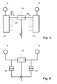
- a circuit variant for an envelope correlation is a circuit variant for an envelope correlation and in Fig. 6 a circuit variant shown for a time correlation.
- the frequency separator (29) has individual frequency ranges assigned separate outputs (30) on. For example, it is possible to use a separator outlet the frequency range from 0 - 0.5 kHz, the next Separator output (30) the frequency range of 0.5 - 1 kHz and the other frequency ranges additional Assign separator outputs (30).
- Envelope correlators (31) are used to analyze the Determination of sound pressure level differences between the microphones (2,3).
- a time correlator (32) is used and a Coupling takes place according to a bypass Attenuators (33).
- Both the envelope correlation and the time correlation can be technically analog or digital will be realized. In particular, it is thought an improvement by combining the two methods to enable sound detection. For Ensure adequate detection of Loudness differences between the left and right Ear it is appropriate to use the correlation method only to be activated when there is frontal radiation (26) is present.
- Control unit (1) it is possible to make a change make the settings made, without changing the position of the microphones (2, 3). This means that not within the Ears (22) arranged ear housing (4,5) accessed must become.
- the directional microphone (19) can by a corresponding movement of a forearm of the individual (21) can be positioned.
- control unit (17) in the area of Control unit (1) it is possible to have a predefinable gain of signals from one of the microphones (2, 3). This allows the user to avoid his Head towards the desired sound source rotate. It is also possible with the help of the control unit (17) to adjust the volume, make a microphone selection or Specify sound group program selection.
- the transmitters (6, 10) for example, as output amplifiers and the receivers (7, 9) as input amplifiers realized.
- a wireless connection can be used.
- a radio connection can be used to suppress interference for example certain transmission frequencies be reserved, so it is also possible alternative To provide transmission channels or alternative To maintain modulation frequencies.
- a wireless one Transmission can also take place via IR or HF signals.
- the device can have different applications be fed. With the one already described Using it as a hearing aid it is possible to record a sound Via the microphones (2,3) in the area of the ear housing (4,5). Alternatively, it is possible to use one Sound recording via a in the area of the bracelet (27) arranged microphone to perform. Further Sound recordings can be made externally, for example via a telephone, a radio, a surveillance microphone, Consumer electronics devices, personal computers or alarm detector.
- the signals are processed in the area of the central unit, which is the comparator (12), the level limiter (13), the frequency filter (20) and a corresponding amplifier (34) can have.
- the comparison of the time and level difference between the spectral components of the left and Right microphone signal optionally leads to noise suppression.
- the signal components with time and Level difference not increased. A user of the device is thus able to primarily perceive the sound source, to which he has the front of his head turns.
- the microphones (2, 3) are inside the Ohmuscheln arranged, so are those coming from behind Signals attenuated by the auricle. Recognizes the comparator (12) that almost exclusively signals with There is no time and level difference sound suppression made. For example, if a conversation partner is on the left or right side of the user sits and talks and a conversation partner sitting opposite is silent. When recording sound over that in the area of the bracelet (27) arranged microphone or for sound recordings External audio units do not suppress side noise carried out.
- the central unit and the components within the Ear case (4,5) are in the area of the ear case (4,5) no amplifier and no power supply required. If necessary, a preamplifier can be used be useful for sending.
- the sound is reproduced via at least one of the loudspeakers in the area of the ear housing (4.5). If the side noise suppression at one Inserted inner ear implant, so the side sound suppressed Signal fed to the processor that the controls implanted electrodes. Through the electrodes there is a charm of the Hömerven.
- a microphone in the area of the central unit For applications outside the area of application hearing aids are picked up by a microphone in the area of the central unit. Through signal processing in the area of the central unit can be optional noise suppression can be carried out. The sound is reproduced externally, for example via the same device, a telephone, a radio, a personal computer or an alarm device.
- an external sound recording can, for example, over a telephone, a radio security microphone, a consumer electronics device, a personal computer or an alarm device respectively.
- the signal processing in the central unit can optionally with a speech recognition or Speech generation.
- a Sound reproduction takes place with an external sound recording via at least one speaker in one Ear case (4,5). Sound reproduction is also conceivable via a loudspeaker in the area of Central unit to perform.
- the signal transmission between the microphones (2,3) in the area of the ear housing (4,5) and the central unit can be done both analog and digital. It is also possible to use analog signal processing or digitally. According to the respective Boundary conditions is also a mixed analog and digital processing possible. According to each selected processing sequence will be analog-to-digital conversions or digital-to-analog conversions carried out. With a partial analog version is particularly thought of reinforcement operations to be carried out analogously.
- the decomposition can be done, for example, by Fast Fourier Transformations (FFT) or through the use of filter banks respectively. After performing the separation in the frequency bands it is possible to suppress side noise, a frequency response correction, a dynamic compression, a dehumidification or other procedures to improve speech intelligibility perform.
- FFT Fast Fourier Transformations
- Dynamic compression takes into account that a dynamic range for normal hearing within from 0 dB to 130 dB. In the event of hearing loss are noises until a certain one Perceived threshold of volume. This is also frequency dependent. The dynamic range is restricted. E.g. a linear gain of all noises, so should be amplitudes above the discomfort threshold, for example above a limit of 130 dB, be cut off. It is therefore cheaper to Maintain amplitude course and the limited Compress dynamic range.
- the dehumidification possible to provide an anti-feedback.
- the signal digitized it can be determined whether hall influences and there can be a minimization of the Hall effect can be performed. Digitization enables an evaluation of the signals. About that it can also be determined whether by the amplifier an additional reinforcement of the already reinforced Signals has been performed. By a time delay of the signal, it is possible to occur To suppress feedback effects.
- Improving speech intelligibility can be performed by special algorithms that lead to an increase in sharpness of speech.
- All the measures described above for influencing the signal can be used as algorithms for editing be formulated on a digital computer. It is advisable the algorithms each one specific Spectral component to increase or decrease the dynamic value assign. After a corresponding split of the signal into the spectral components and the application one of the algorithms described Recombination to a resulting overall signal. This can be done, for example, by inverse Fast Fourier Transformation or one of the initial filtering appropriate inverse filtering is done.
Landscapes
- Engineering & Computer Science (AREA)
- Acoustics & Sound (AREA)
- Neurosurgery (AREA)
- Otolaryngology (AREA)
- Physics & Mathematics (AREA)
- General Health & Medical Sciences (AREA)
- Health & Medical Sciences (AREA)
- Signal Processing (AREA)
- Computer Networks & Wireless Communication (AREA)
- Measurement And Recording Of Electrical Phenomena And Electrical Characteristics Of The Living Body (AREA)
- Circuit For Audible Band Transducer (AREA)
- Measuring Pulse, Heart Rate, Blood Pressure Or Blood Flow (AREA)
- Headphones And Earphones (AREA)
- Orthopedics, Nursing, And Contraception (AREA)
- Telephone Function (AREA)
Claims (10)
- Appareil d'assistance auditive qui comporte deux microphones (2,3) reliés à une unité de commande et qui alimentent l'unité de commande (1) en signaux d'entrée, appareil dans le cas duquel l'unité de commande (1) transmet au moins un signal de sortie à un élément de transmission au moins et dans le cas duquel l'unité de commande (1) a été prévue espacée des microphones (2,3), de même que dans le cas duquel les microphones (2,3) sont contenus dans des boítiers d'écouteurs (4,5) qui peuvent être placés chacun dans la région d'une oreille humaine (22) et dans le cas duquel les boítiers d'écouteurs (4,5) sont munis chacun d'un émetteur (6) qui communique avec un récepteur (7) prévu dans la région de l'unité de commande (1) et dans le cas duquel dans la région de l'un au moins des boítiers d'écouteurs (4,5) a été prévu l'un des éléments de transmission (8), élément de transmission qui est muni d'un récepteur (9) qui communique avec un émetteur (10) prévu dans la région de l'unité de commande (1), de même que dans le cas duquel, dans la région de l'unité de commande (1), il a été prévu un analyseur (12) destiné à l'appréciation des signaux des microphones (2,3), l'appareil d'audition étant caractérisé en ce que l'analyseur (12) modifie la puissance de sortie de l'unité de commande (1 ) en vue de l'adaptation à une reproduction du son dans l'espace, en ce que les signaux de sortie des microphones (2,3) sont évalués avec comparaison par l'analyseur (12) et en ce que dans la région d'au moins un des éléments de transmission (8) il a été prévu un amplificateur d'écoute (11) et en ce que l'unité de commande (1) comporte une unité d'actionnement (17) pour les entrées manuelles.
- Appareil suivant la revendication 1, caractérisé en ce que pour la transmission des données des émetteurs (6, 10) aux récepteurs (7,9), il a été prévu une zone de transmission.
- Appareil suivant la revendication 1, caractérisé en ce que les émetteurs (6,10) sont reliés aux récepteurs (7,9) par un conducteur.
- Appareil suivant l'une quelconque des revendications 1 à 3 caractérisé en ce que l'analyseur (12) est muni d'un corrélateur à enveloppante (31).
- Appareil suivant l'une quelconque des revendications 1 à 4 caractérisé en ce que l'analyseur (12) est muni d'un corrélateur de temps (32).
- Appareil suivant l'une quelconque des revendications 1 à 5 caractérisé en ce que l'unité de commande (1) est montée dans la région d'un bracelet (27) qui peut être porté au niveau de l'articulation du poignet (28).
- Appareil suivant l'une quelconque des revendications 1 à 6, caractérisé en ce que dans la région de l'unité de commande (1) il a été prévu un microphone de correction (19).
- Appareil suivant l'une quelconque des revendications 1 à7 , caractérisé en ce que dans la région de l'unité de commande (1) il a été prévu, pour au moins un canal de transmission, un limiteur de niveau (13).
- Appareil suivant l'une quelconque des revendications 1 à 8 caractérisé en ce que dans la région de l'unité de commande (1) il a été prévu un amplificateur principal (43).
- Appareil suivant l'une quelconque des revendications 1 à 9, caractérisé en ce que dans la région de l'un au moins des boítiers d'écouteurs (4,5), il a été monté une pile d'écoute (15).
Priority Applications (4)
| Application Number | Priority Date | Filing Date | Title |
|---|---|---|---|
| EP94120781A EP0723381B2 (fr) | 1994-12-27 | 1994-12-27 | Dispositif d'assistance auditive |
| DE59402320T DE59402320D1 (de) | 1994-12-27 | 1994-12-27 | Vorrichtung zur Hörunterstützung |
| DK94120781T DK0723381T4 (da) | 1994-12-27 | 1994-12-27 | Apparat til hørehjælp |
| AT94120781T ATE151217T1 (de) | 1994-12-27 | 1994-12-27 | Vorrichtung zur hörunterstützung |
Applications Claiming Priority (1)
| Application Number | Priority Date | Filing Date | Title |
|---|---|---|---|
| EP94120781A EP0723381B2 (fr) | 1994-12-27 | 1994-12-27 | Dispositif d'assistance auditive |
Publications (3)
| Publication Number | Publication Date |
|---|---|
| EP0723381A1 EP0723381A1 (fr) | 1996-07-24 |
| EP0723381B1 EP0723381B1 (fr) | 1997-04-02 |
| EP0723381B2 true EP0723381B2 (fr) | 2001-02-07 |
Family
ID=8216570
Family Applications (1)
| Application Number | Title | Priority Date | Filing Date |
|---|---|---|---|
| EP94120781A Expired - Lifetime EP0723381B2 (fr) | 1994-12-27 | 1994-12-27 | Dispositif d'assistance auditive |
Country Status (4)
| Country | Link |
|---|---|
| EP (1) | EP0723381B2 (fr) |
| AT (1) | ATE151217T1 (fr) |
| DE (1) | DE59402320D1 (fr) |
| DK (1) | DK0723381T4 (fr) |
Cited By (1)
| Publication number | Priority date | Publication date | Assignee | Title |
|---|---|---|---|---|
| DE102005042430A1 (de) * | 2005-09-07 | 2007-03-08 | Fachhochschule Ulm | Gehörschutz bei gleichzeitiger Sprachverständlichkeit mit Signalprozessor |
Families Citing this family (1)
| Publication number | Priority date | Publication date | Assignee | Title |
|---|---|---|---|---|
| DE10344032A1 (de) * | 2003-09-23 | 2005-06-23 | Schlegel, Udo D. | Hörsystem verwendbar für schwerhörige Personen |
Family Cites Families (7)
| Publication number | Priority date | Publication date | Assignee | Title |
|---|---|---|---|---|
| DE2406218A1 (de) * | 1974-02-09 | 1975-08-21 | Micro Technic Hueber & Co | Hoerhilfsgeraet fuer hoerbehinderte oder schwerhoerige |
| CA1149050A (fr) * | 1980-02-08 | 1983-06-28 | Alfred A.A.A. Tomatis | Appareil auditif |
| EP0298323A1 (fr) * | 1987-07-07 | 1989-01-11 | Siemens Aktiengesellschaft | Appareil aide ouie |
| US4887299A (en) * | 1987-11-12 | 1989-12-12 | Nicolet Instrument Corporation | Adaptive, programmable signal processing hearing aid |
| US5029216A (en) * | 1989-06-09 | 1991-07-02 | The United States Of America As Represented By The Administrator Of The National Aeronautics & Space Administration | Visual aid for the hearing impaired |
| FR2651634B1 (fr) * | 1989-09-06 | 1996-08-23 | France Comte Universite | Perfectionnements aux dispositifs de prothese auditive. |
| DE4327901C1 (de) * | 1993-08-19 | 1995-02-16 | Markus Poetsch | Vorrichtung zur Hörunterstützung |
-
1994
- 1994-12-27 EP EP94120781A patent/EP0723381B2/fr not_active Expired - Lifetime
- 1994-12-27 AT AT94120781T patent/ATE151217T1/de not_active IP Right Cessation
- 1994-12-27 DE DE59402320T patent/DE59402320D1/de not_active Expired - Lifetime
- 1994-12-27 DK DK94120781T patent/DK0723381T4/da active
Non-Patent Citations (3)
| Title |
|---|
| Bodden M.: Binaurale Signalverarbeitung: Modellierung der Richtungserkennung und des Coktail-Party-Effektes, Fortschritt Berichte, VDI, Reihe 17, Nr.85,VDI Verlag, 1992 † |
| Gaik w.: Untersuchungen zur binauralen Verarbeitung kopfbezogener Signale, Fortschritt Berichte, VDI, Reihe 17,, Nr.63, VDI Verlag, 1990 † |
| Peissig J.: Binaurale Hörgerätestrategien in komplexen Störschallsituationen Dissertation Universität Göttingen, 1992 † |
Cited By (1)
| Publication number | Priority date | Publication date | Assignee | Title |
|---|---|---|---|---|
| DE102005042430A1 (de) * | 2005-09-07 | 2007-03-08 | Fachhochschule Ulm | Gehörschutz bei gleichzeitiger Sprachverständlichkeit mit Signalprozessor |
Also Published As
| Publication number | Publication date |
|---|---|
| DK0723381T4 (da) | 2001-06-18 |
| DE59402320D1 (de) | 1997-05-07 |
| EP0723381B1 (fr) | 1997-04-02 |
| DK0723381T3 (da) | 1997-10-06 |
| EP0723381A1 (fr) | 1996-07-24 |
| ATE151217T1 (de) | 1997-04-15 |
Similar Documents
| Publication | Publication Date | Title |
|---|---|---|
| DE69022762T2 (de) | Vorrichtung zur Lärmverminderung. | |
| EP1489885B1 (fr) | Procédé pour l'opération d'une prothèse auditive ainsi qu'une prothèse auditive avec un système de microphone dans lequel différents caractéristiques de directivité sont sélectionnables | |
| EP3222057B1 (fr) | Procédé et dispositif de détection rapide de la voix naturelle | |
| DE10146886B4 (de) | Hörgerät mit automatischer Umschaltung auf Hörspulenbetrieb | |
| DE10331956C5 (de) | Hörhilfegerät sowie Verfahren zum Betrieb eines Hörhilfegerätes mit einem Mikrofonsystem, bei dem unterschiedliche Richtcharakteistiken einstellbar sind | |
| DE102018216667B3 (de) | Verfahren zur Verarbeitung von Mikrofonsignalen in einem Hörsystem sowie Hörsystem | |
| EP2164283B1 (fr) | Appareil auditif et fonctionnement d'un appareil auditif doté d'une transposition de fréquence | |
| EP3104627B1 (fr) | Procédé d'amélioration d'un signal d'enregistrement dans un système auditif | |
| EP2645743B1 (fr) | Appareil auditif pour un traitement binaural et procédé destiné à préparer un traitement binaural | |
| EP1931172A1 (fr) | Prothèse auditive avec suppression du bruit et procédé correspondant | |
| EP2229010A2 (fr) | Procédé de compensation d'un bruit parasite dans un appareil auditif, appareil auditif et procédé d'adaptation de celui-ci | |
| DE10334396B3 (de) | Hörhilfegerät sowie Verfahren zum Betrieb eines Hörhilfegerätes mit einem Mikrofonsystem, bei dem unterschiedliche Richtcharakteristiken einstellbar sind | |
| DE4327901C1 (de) | Vorrichtung zur Hörunterstützung | |
| DE102006015497B4 (de) | Audiosystem und Verfahren sowie Computerprogramm und Datenträger der das Computerprogramm enthält zur Anpassung der Übertragungsfunktion eines Audiosystems mittels Sprachsteuerung | |
| EP0723381B2 (fr) | Dispositif d'assistance auditive | |
| DE102015212609A1 (de) | Verfahren zum Betrieb eines Hörgerätesystems und Hörgerätesystem | |
| EP4149121A1 (fr) | Procédé de fonctionnement d'un appareil auditif | |
| EP3913618A1 (fr) | Procédé de fonctionnement d'un appareil auditif et appareil auditif | |
| DE19926552B4 (de) | Kopfhörer mit Mikrofon | |
| DE102023200412B3 (de) | Verfahren zum Betrieb eines Hörgeräts | |
| DE102023202437B4 (de) | Verfahren zur Lokalisierung einer Schallquelle für ein binaurales Hörsystem | |
| DE102020201615B3 (de) | Hörsystem mit mindestens einem im oder am Ohr des Nutzers getragenen Hörinstrument sowie Verfahren zum Betrieb eines solchen Hörsystems | |
| DE102022202266A1 (de) | Verfahren zum Betrieb eines Hörgeräts | |
| EP4311269A1 (fr) | Procédé de fonctionnement d'un appareil auditif binaural, appareil auditif binaural et logiciel | |
| DE10115714A1 (de) | Headset |
Legal Events
| Date | Code | Title | Description |
|---|---|---|---|
| PUAI | Public reference made under article 153(3) epc to a published international application that has entered the european phase |
Free format text: ORIGINAL CODE: 0009012 |
|
| 17P | Request for examination filed |
Effective date: 19950902 |
|
| AK | Designated contracting states |
Kind code of ref document: A1 Designated state(s): AT BE CH DE DK ES FR GB GR IE IT LI LU MC NL PT SE |
|
| GRAG | Despatch of communication of intention to grant |
Free format text: ORIGINAL CODE: EPIDOS AGRA |
|
| GRAH | Despatch of communication of intention to grant a patent |
Free format text: ORIGINAL CODE: EPIDOS IGRA |
|
| GRAH | Despatch of communication of intention to grant a patent |
Free format text: ORIGINAL CODE: EPIDOS IGRA |
|
| GRAA | (expected) grant |
Free format text: ORIGINAL CODE: 0009210 |
|
| AK | Designated contracting states |
Kind code of ref document: B1 Designated state(s): AT BE CH DE DK ES FR GB GR IE IT LI LU MC NL PT SE |
|
| PG25 | Lapsed in a contracting state [announced via postgrant information from national office to epo] |
Ref country code: NL Effective date: 19970402 Ref country code: IT Free format text: LAPSE BECAUSE OF FAILURE TO SUBMIT A TRANSLATION OF THE DESCRIPTION OR TO PAY THE FEE WITHIN THE PRE;WARNING: LAPSES OF ITALIAN PATENTS WITH EFFECTIVE DATE BEFORE 2007 MAY HAVE OCCURRED AT ANY TIME BEFORE 2007. THE CORRECT EFFECTIVE DATE MAY BE DIFFERENT FROM THE ONE RECORDED.SCRIBED TIME-LIMIT Effective date: 19970402 Ref country code: GR Free format text: LAPSE BECAUSE OF FAILURE TO SUBMIT A TRANSLATION OF THE DESCRIPTION OR TO PAY THE FEE WITHIN THE PRESCRIBED TIME-LIMIT Effective date: 19970402 Ref country code: ES Free format text: THE PATENT HAS BEEN ANNULLED BY A DECISION OF A NATIONAL AUTHORITY Effective date: 19970402 |
|
| REF | Corresponds to: |
Ref document number: 151217 Country of ref document: AT Date of ref document: 19970415 Kind code of ref document: T |
|
| REG | Reference to a national code |
Ref country code: CH Ref legal event code: EP |
|
| REF | Corresponds to: |
Ref document number: 59402320 Country of ref document: DE Date of ref document: 19970507 |
|
| PG25 | Lapsed in a contracting state [announced via postgrant information from national office to epo] |
Ref country code: SE Effective date: 19970702 Ref country code: PT Effective date: 19970702 |
|
| GBT | Gb: translation of ep patent filed (gb section 77(6)(a)/1977) |
Effective date: 19970707 |
|
| REG | Reference to a national code |
Ref country code: IE Ref legal event code: FG4D Free format text: 73065 |
|
| EN | Fr: translation not filed | ||
| NLV1 | Nl: lapsed or annulled due to failure to fulfill the requirements of art. 29p and 29m of the patents act | ||
| REG | Reference to a national code |
Ref country code: DK Ref legal event code: T3 |
|
| ET | Fr: translation filed | ||
| REG | Reference to a national code |
Ref country code: FR Ref legal event code: RN |
|
| PLBQ | Unpublished change to opponent data |
Free format text: ORIGINAL CODE: EPIDOS OPPO |
|
| PLBI | Opposition filed |
Free format text: ORIGINAL CODE: 0009260 |
|
| REG | Reference to a national code |
Ref country code: FR Ref legal event code: FC |
|
| PG25 | Lapsed in a contracting state [announced via postgrant information from national office to epo] |
Ref country code: LU Free format text: LAPSE BECAUSE OF NON-PAYMENT OF DUE FEES Effective date: 19971227 |
|
| PG25 | Lapsed in a contracting state [announced via postgrant information from national office to epo] |
Ref country code: LI Free format text: LAPSE BECAUSE OF NON-PAYMENT OF DUE FEES Effective date: 19971231 Ref country code: CH Free format text: LAPSE BECAUSE OF NON-PAYMENT OF DUE FEES Effective date: 19971231 Ref country code: BE Free format text: LAPSE BECAUSE OF NON-PAYMENT OF DUE FEES Effective date: 19971231 |
|
| 26 | Opposition filed |
Opponent name: PROF. DR.DR. BIRGER KOLLMEIER Effective date: 19971217 |
|
| PLBF | Reply of patent proprietor to notice(s) of opposition |
Free format text: ORIGINAL CODE: EPIDOS OBSO |
|
| PLAB | Opposition data, opponent's data or that of the opponent's representative modified |
Free format text: ORIGINAL CODE: 0009299OPPO |
|
| PG25 | Lapsed in a contracting state [announced via postgrant information from national office to epo] |
Ref country code: IE Free format text: LAPSE BECAUSE OF NON-PAYMENT OF DUE FEES Effective date: 19980330 |
|
| REG | Reference to a national code |
Ref country code: IE Ref legal event code: FD4D Ref document number: 73065 Country of ref document: IE |
|
| R26 | Opposition filed (corrected) |
Opponent name: PROF. DR.DR. BIRGER KOLLMEIER/DR. JUERGEN PEISSIG Effective date: 19971217 |
|
| PLBF | Reply of patent proprietor to notice(s) of opposition |
Free format text: ORIGINAL CODE: EPIDOS OBSO |
|
| BERE | Be: lapsed |
Owner name: POETSCH MARKUS Effective date: 19971231 |
|
| PG25 | Lapsed in a contracting state [announced via postgrant information from national office to epo] |
Ref country code: MC Free format text: LAPSE BECAUSE OF NON-PAYMENT OF DUE FEES Effective date: 19980630 |
|
| REG | Reference to a national code |
Ref country code: CH Ref legal event code: PL |
|
| PLBQ | Unpublished change to opponent data |
Free format text: ORIGINAL CODE: EPIDOS OPPO |
|
| PLAB | Opposition data, opponent's data or that of the opponent's representative modified |
Free format text: ORIGINAL CODE: 0009299OPPO |
|
| PLAW | Interlocutory decision in opposition |
Free format text: ORIGINAL CODE: EPIDOS IDOP |
|
| PLBQ | Unpublished change to opponent data |
Free format text: ORIGINAL CODE: EPIDOS OPPO |
|
| PLAB | Opposition data, opponent's data or that of the opponent's representative modified |
Free format text: ORIGINAL CODE: 0009299OPPO |
|
| R26 | Opposition filed (corrected) |
Opponent name: PROF. DR.DR. BIRGER KOLLMEIER/DR. JUERGEN PEISSIG Effective date: 19971217 |
|
| R26 | Opposition filed (corrected) |
Opponent name: PROF. DR.DR. BIRGER KOLLMEIER/DR. JUERGEN PEISSIG Effective date: 19971217 |
|
| PLAW | Interlocutory decision in opposition |
Free format text: ORIGINAL CODE: EPIDOS IDOP |
|
| PUAH | Patent maintained in amended form |
Free format text: ORIGINAL CODE: 0009272 |
|
| STAA | Information on the status of an ep patent application or granted ep patent |
Free format text: STATUS: PATENT MAINTAINED AS AMENDED |
|
| 27A | Patent maintained in amended form |
Effective date: 20010207 |
|
| AK | Designated contracting states |
Kind code of ref document: B2 Designated state(s): AT BE CH DE DK ES FR GB GR IE IT LI LU MC NL PT SE |
|
| ET3 | Fr: translation filed ** decision concerning opposition | ||
| GBTA | Gb: translation of amended ep patent filed (gb section 77(6)(b)/1977) | ||
| REG | Reference to a national code |
Ref country code: DK Ref legal event code: T4 |
|
| REG | Reference to a national code |
Ref country code: GB Ref legal event code: IF02 |
|
| REG | Reference to a national code |
Ref country code: GB Ref legal event code: 732E |
|
| REG | Reference to a national code |
Ref country code: FR Ref legal event code: TP |
|
| PGFP | Annual fee paid to national office [announced via postgrant information from national office to epo] |
Ref country code: DK Payment date: 20081223 Year of fee payment: 15 |
|
| PGFP | Annual fee paid to national office [announced via postgrant information from national office to epo] |
Ref country code: AT Payment date: 20081230 Year of fee payment: 15 |
|
| PGFP | Annual fee paid to national office [announced via postgrant information from national office to epo] |
Ref country code: FR Payment date: 20081029 Year of fee payment: 15 |
|
| PGFP | Annual fee paid to national office [announced via postgrant information from national office to epo] |
Ref country code: GB Payment date: 20091214 Year of fee payment: 16 |
|
| REG | Reference to a national code |
Ref country code: DK Ref legal event code: EBP |
|
| PG25 | Lapsed in a contracting state [announced via postgrant information from national office to epo] |
Ref country code: AT Free format text: LAPSE BECAUSE OF NON-PAYMENT OF DUE FEES Effective date: 20091227 |
|
| REG | Reference to a national code |
Ref country code: FR Ref legal event code: ST Effective date: 20100831 |
|
| PG25 | Lapsed in a contracting state [announced via postgrant information from national office to epo] |
Ref country code: FR Free format text: LAPSE BECAUSE OF NON-PAYMENT OF DUE FEES Effective date: 20091231 |
|
| PG25 | Lapsed in a contracting state [announced via postgrant information from national office to epo] |
Ref country code: DK Free format text: LAPSE BECAUSE OF NON-PAYMENT OF DUE FEES Effective date: 20100104 |
|
| GBPC | Gb: european patent ceased through non-payment of renewal fee |
Effective date: 20101227 |
|
| PG25 | Lapsed in a contracting state [announced via postgrant information from national office to epo] |
Ref country code: GB Free format text: LAPSE BECAUSE OF NON-PAYMENT OF DUE FEES Effective date: 20101227 |
|
| PGFP | Annual fee paid to national office [announced via postgrant information from national office to epo] |
Ref country code: DE Payment date: 20130521 Year of fee payment: 19 |
|
| REG | Reference to a national code |
Ref country code: DE Ref legal event code: R119 Ref document number: 59402320 Country of ref document: DE |
|
| REG | Reference to a national code |
Ref country code: DE Ref legal event code: R119 Ref document number: 59402320 Country of ref document: DE Effective date: 20140701 |
|
| PG25 | Lapsed in a contracting state [announced via postgrant information from national office to epo] |
Ref country code: DE Free format text: LAPSE BECAUSE OF NON-PAYMENT OF DUE FEES Effective date: 20140701 |