EP0722155A1 - Sende-Empfänger für kontaktloses IC-Kartensystem - Google Patents
Sende-Empfänger für kontaktloses IC-Kartensystem Download PDFInfo
- Publication number
- EP0722155A1 EP0722155A1 EP96100221A EP96100221A EP0722155A1 EP 0722155 A1 EP0722155 A1 EP 0722155A1 EP 96100221 A EP96100221 A EP 96100221A EP 96100221 A EP96100221 A EP 96100221A EP 0722155 A1 EP0722155 A1 EP 0722155A1
- Authority
- EP
- European Patent Office
- Prior art keywords
- frequency
- transponder
- resonant
- interrogator
- carrier wave
- Prior art date
- Legal status (The legal status is an assumption and is not a legal conclusion. Google has not performed a legal analysis and makes no representation as to the accuracy of the status listed.)
- Granted
Links
Images


Classifications
-
- G—PHYSICS
- G01—MEASURING; TESTING
- G01S—RADIO DIRECTION-FINDING; RADIO NAVIGATION; DETERMINING DISTANCE OR VELOCITY BY USE OF RADIO WAVES; LOCATING OR PRESENCE-DETECTING BY USE OF THE REFLECTION OR RERADIATION OF RADIO WAVES; ANALOGOUS ARRANGEMENTS USING OTHER WAVES
- G01S13/00—Systems using the reflection or reradiation of radio waves, e.g. radar systems; Analogous systems using reflection or reradiation of waves whose nature or wavelength is irrelevant or unspecified
- G01S13/74—Systems using reradiation of radio waves, e.g. secondary radar systems; Analogous systems
- G01S13/75—Systems using reradiation of radio waves, e.g. secondary radar systems; Analogous systems using transponders powered from received waves, e.g. using passive transponders, or using passive reflectors
- G01S13/751—Systems using reradiation of radio waves, e.g. secondary radar systems; Analogous systems using transponders powered from received waves, e.g. using passive transponders, or using passive reflectors wherein the responder or reflector radiates a coded signal
- G01S13/753—Systems using reradiation of radio waves, e.g. secondary radar systems; Analogous systems using transponders powered from received waves, e.g. using passive transponders, or using passive reflectors wherein the responder or reflector radiates a coded signal using frequency selective elements, e.g. resonator
-
- B—PERFORMING OPERATIONS; TRANSPORTING
- B61—RAILWAYS
- B61L—GUIDING RAILWAY TRAFFIC; ENSURING THE SAFETY OF RAILWAY TRAFFIC
- B61L25/00—Recording or indicating positions or identities of vehicles or vehicle trains or setting of track apparatus
- B61L25/02—Indicating or recording positions or identities of vehicles or vehicle trains
- B61L25/04—Indicating or recording train identities
- B61L25/045—Indicating or recording train identities using reradiating tags
-
- G—PHYSICS
- G06—COMPUTING; CALCULATING OR COUNTING
- G06K—GRAPHICAL DATA READING; PRESENTATION OF DATA; RECORD CARRIERS; HANDLING RECORD CARRIERS
- G06K7/00—Methods or arrangements for sensing record carriers, e.g. for reading patterns
- G06K7/0008—General problems related to the reading of electronic memory record carriers, independent of its reading method, e.g. power transfer
Definitions
- This invention relates to a non-contact integrated circuit (hereinafter "IC" card system which transmits and receives signals between an interrogator (a reader-writer) and a transponder (a card), in particular, to a transmitter-receiver used for the interrogator.
- IC non-contact integrated circuit
- Non-contact IC card systems which transmit and receive signals between an interrogator (a reader-writer) and a transponder (a card) by the electromagnetic coupling method or electromagnetic induction method.
- Fig. 3 is a block diagram commonly used in such an electromagnetic coupling type non-contact IC card system.
- the interrogator modulates a carrier wave generated in an OSC (oscillator) 1, through a modulating circuit 3 in accordance with signals from a data-processing circuit 2, and the modulated wave is amplified in a constant-current driver circuit 4 and then transmitted to the transponder through constant-current drive of an antenna coil 5.
- the transponder receives signals from the interrogator through an antenna coil 11, whereupon the received signals are demodulated in a demodulating circuit 13 and are sent to a data-processing circuit 14.
- the data are processed in the data-processing circuit 14, and the preset data are sent to a modulating circuit 15 and then sent out to the interrogator through the antenna coil 11.
- the interrogator receives the signals sent from the transponder through the antenna coil 5, whereupon the signals are demodulated in a demodulating circuit 6 and then sent to the data-processing circuit 2 to process the data to make judgement or the like.
- the transponder is provided with a tuned resonant circuit A comprised of the antenna coil 11 and a capacitor 12.
- the antenna coil 11 and the capacitor 12 are required to have the desired inductance and capacitance.
- the precision of capacitance of the capacitor 12 is about plus-minus 5% at best.
- the form of the antenna coil 11 it can be roughly grouped into two types, one of which is of the type of a wound wire and the other of which is of the type of an etched copper-clad plate.
- the precision of inductance of the wound wire type is about plus-minus 5%.
- the resonant circuit in order to efficiently convert into voltage the magnetic field induced in the antenna coil 11, it is more preferable for the resonant circuit to have a higher Q (quality factor).
- Q quality factor
- making the Q of the resonant circuit A higher results in a narrow frequency bandwidth selected in the resonant circuit A.
- the frequency selected in the resonant circuit A turns outside the range of the tolerance between the carrier wave frequency of the interrogator and the resonant frequency of the transponder, thereby causing the problems that the signals from the interrogator can not be received.
- the Q of the resonant circuit A is intentionally lowered to the extent that the error between the carrier wave frequency of the interrogator and the resonant frequency of the transponder does not come into question.
- a special adjustment is made when the transponder is manufactured. That is, a plurality of capacitors are provisionally provided as the capacitor 12 of the resonant circuit A, and some unnecessary capacitors are removed at the time of the adjustment so that the desired resonant frequency F 0 can be obtained, or a troublesome operation is made, e.g., the antenna coil 11 is unwound at the time of the adjustment.
- An object of the present invention is to enable efficient transmission by bringing the carrier wave frequency of the interrogator into agreement with the resonant frequency of the transponder, without lowering the Q of the resonant circuit A of the transponder and also without any special adjustment for controlling the resonant frequency of the transponder to the desired frequency.
- the present inventors have discovered that the above object can be achieved when the interrogator is made to have the function to detect the resonant frequency of the transponder so that the carrier wave frequency of the interrogator is maintained to the frequency thus detected. They have thus accomplished the present invention.
- the invention provides a transmitter-receiver used for an interrogator in a non-contact IC card system which transmits and receives signals between the interrogator and a transponder; the transmitter-receiver comprising;
- the carrier wave oscillating means generates a carrier wave while sweeping an oscillation frequency.
- the carrier wave whose frequency is being swept is transmitted to the transponder, where the impedance of the transponder viewed from the interrogator greatly changes when the carrier wave frequency of the interrogator has come into agreement with the resonant frequency of the transponder, so that a peak voltage (or a dip voltage) is generated in the antenna of the interrogator.
- a carrier wave with a specific frequency which generates this peak voltage (or dip voltage) is detected so that the oscillation frequency of the carrier wave oscillating means is maintained to the specific frequency by the carrier frequency holding means.
- the signals from the data-processing circuit of the interrogator are modulated with the carrier wave having the specific frequency maintained by the carrier wave oscillating means, and the signals thus modulated are sent to the transponder as in the conventional non-contact IC card system.
- the transponder since the frequency of the carrier wave is in agreement with the resonant frequency of the transponder, the transponder can receive the signals in a high signal transmission efficiency.
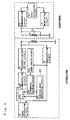
- Fig. 1 is a block diagram of a non-contact IC card system employing as the interrogator a device according to an embodiment of the present invention.
- Figs. 2A to 2D show waveforms in the circuits of the non-contact IC card system according to the present invention.
- Fig. 3 is a block diagram of a conventional non-contact IC card system.
- Fig. 1 is a block diagram of a non-contact IC card system in which an interrogator comprising the device according to an embodiment of the present invention is set up in combination with the conventional transponder shown in Fig. 3.
- Figs. 2A to 2D show waveforms in the circuits of this non-contact IC card system.
- the interrogator shown in Fig. 1 has a data-processing circuit 2, a modulating circuit 3, a constant-current driver circuit 4, an antenna coil 5, and a demodulating circuit 6.
- the signals from the data-processing circuit 2 modulate a carrier wave in the modulating circuit 3, and the modulated wave is amplified in the constant-current driver circuit 4 and then transmitted to the transponder through the antenna coil 5.
- the signals received from the transponder are demodulated in the demodulating circuit 6 and are sent to the data-processing circuit 2 to process the data to make judgement or the like.
- the interrogator shown in Fig. 1 is different in that it has a saw-tooth wave generating circuit 21 and a voltage control oscillating circuit (VCO) 22, which constitute a carrier wave oscillating means 20, and is also different in that it has a peak search circuit 23 and a frequency holding circuit 24.
- This peak search circuit 23 constitutes together with the demodulating circuit 6 a resonant wave detecting means for detecting the resonant frequency of the transponder.
- the frequency holding circuit 24 is connected to the voltage control oscillating circuit 22 as shown by a solid line in the drawing, or connected to the saw-tooth wave generating circuit 21 as shown by a broken line in the drawing, to constitute the carrier frequency holding means.
- the frequency of the carrier wave is first determined in the following way: A saw-tooth wave as shown in Fig. 2A is generated by the saw-tooth wave generating circuit 21. By this saw-tooth wave, a carrier wave whose frequency is swept as shown in Fig. 2B is generated by the voltage control oscillating circuit 22. This carrier wave is transmitted to the transponder after it has been modulated, or without being modulated, in the modulating circuit 3.
- the impedance of transponder as viewed from the interrogator greatly changes when the carrier wave frequency of the interrogator has come into agreement with the resonant frequency of the resonant circuit A of the transponder.
- a peak voltage (or a dip voltage) is generated at both ends of the antenna coil 5.
- the demodulating circuit 6 demodulates as shown in Fig. 2C the changes in voltage at the both ends of the antenna coil 5, containing the peak voltage.
- the peak search circuit 23 detects the peak frequency of this peak waveform and sends out a trigger pulse to the frequency holding circuit 24.
- the frequency holding circuit 24 maintains the drive voltage of the voltage control oscillating circuit 22 or saw-tooth wave generating circuit 21 to a constant voltage V 0 as shown in Fig. 2D.
- the voltage control oscillating circuit 22 maintains the oscillation of a carrier wave having a constant frequency, oscillating at that voltage V 0 .
- the carrier wave determined in this way comes into agreement with the resonant frequency of the transponder.
- the signals sent from the data-processing circuit 2 modulate this carrier wave.
- the signals thus modulated are amplified in the constant-current driver circuit 4 and then sent to the transponder through the antenna coil 5.
- the transponder since the frequency of the carrier wave is in agreement with the resonant frequency of the transponder, the transponder can receive the signals in a high signal transmission efficiency.
- the present invention may take various modes.
- the carrier wave oscillating means 20 which has the saw-tooth wave generating circuit 21 and the voltage control oscillating circuit (VCO) 22, may be any oscillating means in the present invention so long as it can sweep the oscillation frequency.
- VCO voltage control oscillating circuit
- a step-form wave generating circuit or the like may be used.
- the present invention can also be widely applied in interrogators of electromagnetic coupling type or electromagnetic induction type non-contact IC card systems.
- the antenna coil 5 is fed through the constant-current driver circuit 4
- the present invention can also be applied in an instance where the antenna coil 5 is fed through a constant-voltage driver circuit or the like.
- the present invention makes it possible to bring the carrier wave frequency of the interrogator into agreement with the resonant frequency of the transponder, without any special adjustment for controlling the resonant frequency of the transponder to the desired frequency. Hence, it becomes unnecessary to lower the Q of the resonant circuit A of the transponder. Thus, it becomes possible to drive the non-contact IC card system in a high signal transmission efficiency and with ease.
- a transmitter-receiver used for the interrogator comprises a carrier wave oscillating means capable of sweeping an oscillation frequency, a resonant wave detecting means for detecting the resonant frequency of the transponder among carrier waves generated by the carrier wave oscillating means, and a carrier frequency holding means for maintaining the oscillation frequency of the carrier wave oscillating means to the frequency detected by the resonant wave detecting means.
- the system can be driven in a high transmission efficiency by bringing the carrier wave frequency of the interrogator into agreement with the resonant frequency of the transponder, without lowering the Q of the resonant circuit A of the transponder and also without any special adjustment for controlling the resonant frequency of the transponder to the desired frequency.
Applications Claiming Priority (3)
| Application Number | Priority Date | Filing Date | Title |
|---|---|---|---|
| JP7019826A JP2698766B2 (ja) | 1995-01-11 | 1995-01-11 | 非接触式icカードシステム用送受信装置 |
| JP19826/95 | 1995-01-11 | ||
| JP1982695 | 1995-01-11 |
Publications (2)
| Publication Number | Publication Date |
|---|---|
| EP0722155A1 true EP0722155A1 (de) | 1996-07-17 |
| EP0722155B1 EP0722155B1 (de) | 2002-04-17 |
Family
ID=12010112
Family Applications (1)
| Application Number | Title | Priority Date | Filing Date |
|---|---|---|---|
| EP96100221A Expired - Lifetime EP0722155B1 (de) | 1995-01-11 | 1996-01-09 | Sende-Empfänger für kontaktloses IC-Kartensystem |
Country Status (4)
| Country | Link |
|---|---|
| US (1) | US5866891A (de) |
| EP (1) | EP0722155B1 (de) |
| JP (1) | JP2698766B2 (de) |
| DE (1) | DE69620658T2 (de) |
Cited By (9)
| Publication number | Priority date | Publication date | Assignee | Title |
|---|---|---|---|---|
| EP0857981A1 (de) * | 1997-02-05 | 1998-08-12 | EM Microelectronic-Marin SA | Basisstation eines Fernabfragesystems mit spannungsgesteuertem und phasengeregeltem Oszillator |
| WO2000043804A2 (en) * | 1999-01-20 | 2000-07-27 | Rf Code, Inc. | Radio frequency identification device |
| US6272320B1 (en) | 1997-02-05 | 2001-08-07 | Em Microelectronic-Marin Sa | Base station for a contactless interrogation system comprising a phase locked and voltage controlled oscillator |
| US6654466B1 (en) | 1997-04-17 | 2003-11-25 | Rohm Co., Ltd. | Data communication equipment, data communication system, and data communication method |
| GB2423674A (en) * | 2005-02-25 | 2006-08-30 | Hewlett Packard Development Co | Writing to transponder devices |
| EP1727079A3 (de) * | 1998-11-05 | 2006-12-27 | Mitsubishi Materials Corporation | Verfahren zur Identifikation überlappender Labels |
| WO2008033006A1 (en) * | 2006-09-15 | 2008-03-20 | N.V. Nederlandsche Apparatenfabriek Nedap | System for communicating with a responder |
| WO2010106374A1 (en) * | 2009-03-20 | 2010-09-23 | Innovision Research & Technology Plc | Near field rf communications apparatus |
| EP2254074A1 (de) * | 2009-05-20 | 2010-11-24 | Legic Identsystems Ag | Schreib-/Lesevorrichtung für kontaktlose Kommunikation |
Families Citing this family (13)
| Publication number | Priority date | Publication date | Assignee | Title |
|---|---|---|---|---|
| US6938825B1 (en) * | 1989-04-24 | 2005-09-06 | Ultracard, Inc. | Data system |
| JP3494800B2 (ja) * | 1996-04-15 | 2004-02-09 | 和夫 坪内 | 無線icカードシステム |
| US6945457B1 (en) | 1996-05-10 | 2005-09-20 | Transaction Holdings Ltd. L.L.C. | Automated transaction machine |
| WO1999039450A1 (en) * | 1998-01-29 | 1999-08-05 | Magellan Technology Pty. Ltd. | A transceiver |
| DE19845065A1 (de) * | 1998-05-15 | 1999-11-25 | Siemens Ag | Vorrichtung zur kontaktlosen Übertragung von Daten |
| JP3916328B2 (ja) * | 1998-07-27 | 2007-05-16 | ローム株式会社 | 非接触通信システム |
| US7036739B1 (en) * | 1999-10-23 | 2006-05-02 | Ultracard, Inc. | Data storage device apparatus and method for using same |
| US8397998B1 (en) | 1999-10-23 | 2013-03-19 | Ultracard, Inc. | Data storage device, apparatus and method for using same |
| US7487908B1 (en) | 1999-10-23 | 2009-02-10 | Ultracard, Inc. | Article having an embedded accessible storage member, apparatus and method for using same |
| JP2001291081A (ja) * | 2000-04-10 | 2001-10-19 | Dainippon Printing Co Ltd | 非接触式情報記憶媒体、その発行装置、外部通信装置及び非接触式情報記憶媒体の通信方法 |
| TW543894U (en) * | 2001-11-09 | 2003-07-21 | Holtek Semiconductor Inc | Signal receiving and transmitting device |
| JP2005538602A (ja) * | 2002-09-05 | 2005-12-15 | コーニンクレッカ フィリップス エレクトロニクス エヌ ヴィ | 電力伝達のために2つの互いに適合されたインピーダンスを備える装置 |
| DE102006028827A1 (de) * | 2006-06-21 | 2008-01-10 | Dynamic Systems Gmbh | Transponder mit elektronischem Speicherchip und magnetischer Ringantenne |
Citations (5)
| Publication number | Priority date | Publication date | Assignee | Title |
|---|---|---|---|---|
| US4023167A (en) * | 1975-06-16 | 1977-05-10 | Wahlstrom Sven E | Radio frequency detection system and method for passive resonance circuits |
| DE2842549A1 (de) * | 1978-09-29 | 1980-04-10 | Siemens Ag | Schaltungsanordnung zur kompensation von frequenzverstimmungen in einem informations-abfragesystem, welches insbesondere zur ermittelung der nummern von eisenbahnfahrzeugen dient |
| DE2842590A1 (de) * | 1978-09-29 | 1980-04-10 | Siemens Ag | Schaltungsanordnung zur nachregelung der frequenz einer schwingungserzeugungsschaltung, insbesondere fuer ein informations-abfragesystem zur ermittlung der nummern von eisenbahnfahrzeugen |
| US4388524A (en) * | 1981-09-16 | 1983-06-14 | Walton Charles A | Electronic identification and recognition system with code changeable reactance |
| EP0625832A1 (de) * | 1993-05-17 | 1994-11-23 | Anatoli Stobbe | Lesegerät für ein Detektierplättchen |
Family Cites Families (19)
| Publication number | Priority date | Publication date | Assignee | Title |
|---|---|---|---|---|
| US3816709A (en) * | 1971-12-27 | 1974-06-11 | C Walton | Electronic identification and recognition system |
| GB2077555A (en) * | 1980-05-27 | 1981-12-16 | Standard Telephones Cables Ltd | Electronic tally apparatus |
| US4818855A (en) * | 1985-01-11 | 1989-04-04 | Indala Corporation | Identification system |
| US4742470A (en) * | 1985-12-30 | 1988-05-03 | Gte Valeron Corporation | Tool identification system |
| JPS62286349A (ja) * | 1986-06-05 | 1987-12-12 | Iwatsu Electric Co Ltd | ボタン電話装置 |
| JPS62286397A (ja) * | 1986-06-05 | 1987-12-12 | Iwatsu Electric Co Ltd | ボタン電話装置 |
| EP0270274A3 (de) * | 1986-12-05 | 1990-01-24 | Meridian Micro-Systems Limited | Antwort- und Abfragegerät |
| EP0309201B1 (de) * | 1987-09-22 | 1993-05-26 | Hitachi Maxell Ltd. | Übertragungsverfahren und -System für kontaktlose I.S.-Karten |
| JPH01150879A (ja) * | 1987-12-08 | 1989-06-13 | Nissan Motor Co Ltd | 無線式生産管理情報媒体 |
| US5289506A (en) * | 1990-02-05 | 1994-02-22 | Sharp Kabushiki Kaisha | Automatic frequency control circuit |
| JPH04329415A (ja) * | 1991-04-30 | 1992-11-18 | Fujitsu Ltd | カード型入出力インタフェース装置及びシステム |
| US5418353A (en) * | 1991-07-23 | 1995-05-23 | Hitachi Maxell, Ltd. | Non-contact, electromagnetically coupled transmission and receiving system for IC cards |
| JP2877594B2 (ja) * | 1991-11-14 | 1999-03-31 | 富士通株式会社 | 入場者管理システム |
| US5214409A (en) * | 1991-12-03 | 1993-05-25 | Avid Corporation | Multi-memory electronic identification tag |
| US5382952A (en) * | 1992-01-22 | 1995-01-17 | Indala Corporation | Transponder for proximity identification system |
| UA37182C2 (uk) * | 1992-08-26 | 2001-05-15 | Брітіш Текнолоджі Груп Лімітед | Система ідентифікації та відповідач для системи ідентифікації |
| NL9201791A (nl) * | 1992-10-15 | 1994-05-02 | Nedap Nv | Het gebruik van een electronisch identificatielabel voor het zoeken van vermiste personen onder sneeuwlawines. |
| US5436622A (en) * | 1993-07-06 | 1995-07-25 | Motorola, Inc. | Variable frequency vibratory alert method and structure |
| DE4428947C1 (de) * | 1994-08-16 | 1996-04-04 | Kiekert Ag | Schließvorrichtung für ein Kraftfahrzeug mit einer Fernbetätigungseinrichtung sowie mit einem Transponder |
-
1995
- 1995-01-11 JP JP7019826A patent/JP2698766B2/ja not_active Expired - Lifetime
-
1996
- 1996-01-09 EP EP96100221A patent/EP0722155B1/de not_active Expired - Lifetime
- 1996-01-09 DE DE69620658T patent/DE69620658T2/de not_active Expired - Lifetime
- 1996-01-11 US US08/584,384 patent/US5866891A/en not_active Expired - Lifetime
Patent Citations (5)
| Publication number | Priority date | Publication date | Assignee | Title |
|---|---|---|---|---|
| US4023167A (en) * | 1975-06-16 | 1977-05-10 | Wahlstrom Sven E | Radio frequency detection system and method for passive resonance circuits |
| DE2842549A1 (de) * | 1978-09-29 | 1980-04-10 | Siemens Ag | Schaltungsanordnung zur kompensation von frequenzverstimmungen in einem informations-abfragesystem, welches insbesondere zur ermittelung der nummern von eisenbahnfahrzeugen dient |
| DE2842590A1 (de) * | 1978-09-29 | 1980-04-10 | Siemens Ag | Schaltungsanordnung zur nachregelung der frequenz einer schwingungserzeugungsschaltung, insbesondere fuer ein informations-abfragesystem zur ermittlung der nummern von eisenbahnfahrzeugen |
| US4388524A (en) * | 1981-09-16 | 1983-06-14 | Walton Charles A | Electronic identification and recognition system with code changeable reactance |
| EP0625832A1 (de) * | 1993-05-17 | 1994-11-23 | Anatoli Stobbe | Lesegerät für ein Detektierplättchen |
Cited By (16)
| Publication number | Priority date | Publication date | Assignee | Title |
|---|---|---|---|---|
| US6272320B1 (en) | 1997-02-05 | 2001-08-07 | Em Microelectronic-Marin Sa | Base station for a contactless interrogation system comprising a phase locked and voltage controlled oscillator |
| EP0857981A1 (de) * | 1997-02-05 | 1998-08-12 | EM Microelectronic-Marin SA | Basisstation eines Fernabfragesystems mit spannungsgesteuertem und phasengeregeltem Oszillator |
| US6654466B1 (en) | 1997-04-17 | 2003-11-25 | Rohm Co., Ltd. | Data communication equipment, data communication system, and data communication method |
| US6982646B2 (en) | 1998-06-02 | 2006-01-03 | Rf Code, Inc. | Object identification system with adaptive transceivers and methods of operation |
| US6362737B1 (en) | 1998-06-02 | 2002-03-26 | Rf Code, Inc. | Object Identification system with adaptive transceivers and methods of operation |
| US6831562B2 (en) | 1998-06-02 | 2004-12-14 | Rf Code, Inc. | Object identification system with adaptive transceivers and methods of operation |
| EP1727079A3 (de) * | 1998-11-05 | 2006-12-27 | Mitsubishi Materials Corporation | Verfahren zur Identifikation überlappender Labels |
| WO2000043804A3 (en) * | 1999-01-20 | 2001-01-04 | Rf Code Inc | Radio frequency identification device |
| EP1462821A1 (de) * | 1999-01-20 | 2004-09-29 | RF Code, Inc. | Vorrichtung zur Identifikation mit Radiofrequenzen |
| WO2000043804A2 (en) * | 1999-01-20 | 2000-07-27 | Rf Code, Inc. | Radio frequency identification device |
| GB2423674A (en) * | 2005-02-25 | 2006-08-30 | Hewlett Packard Development Co | Writing to transponder devices |
| WO2008033006A1 (en) * | 2006-09-15 | 2008-03-20 | N.V. Nederlandsche Apparatenfabriek Nedap | System for communicating with a responder |
| WO2010106374A1 (en) * | 2009-03-20 | 2010-09-23 | Innovision Research & Technology Plc | Near field rf communications apparatus |
| US8965279B2 (en) | 2009-03-20 | 2015-02-24 | Broadcom Europe Limited | Recovering data in a near field communications apparatus |
| US9473208B2 (en) | 2009-03-20 | 2016-10-18 | Broadcom Corporation | Recovering data in a near field communication apparatus |
| EP2254074A1 (de) * | 2009-05-20 | 2010-11-24 | Legic Identsystems Ag | Schreib-/Lesevorrichtung für kontaktlose Kommunikation |
Also Published As
| Publication number | Publication date |
|---|---|
| DE69620658D1 (de) | 2002-05-23 |
| DE69620658T2 (de) | 2002-08-22 |
| JPH08191258A (ja) | 1996-07-23 |
| JP2698766B2 (ja) | 1998-01-19 |
| EP0722155B1 (de) | 2002-04-17 |
| US5866891A (en) | 1999-02-02 |
Similar Documents
| Publication | Publication Date | Title |
|---|---|---|
| EP0722155A1 (de) | Sende-Empfänger für kontaktloses IC-Kartensystem | |
| US6473028B1 (en) | Detection of the distance between an electromagnetic transponder and a terminal | |
| EP0615136B1 (de) | Verfahren zum Abstimmen von elektronischen Antwortgeräten | |
| EP0623260B1 (de) | Transponder für ein annäherungsidentifikationssystem | |
| EP0722094A1 (de) | Sende-Empfänger für kontaktloses IC-Kartensystem | |
| EP0537378B1 (de) | Verfahren zum Lesen von gespeicherten Daten eines passiven Antwortgerätes durch eine Abfrageinrichtung mit einem Empfangsteil | |
| US6650226B1 (en) | Detection, by an electromagnetic transponder reader, of the distance separating it from a transponder | |
| EP0377257A1 (de) | Identifizierungssystem | |
| US5519729A (en) | Method of and device for transmitting serial data structures in systems for identifying information carriers | |
| US4963887A (en) | Full duplex transponder system | |
| US8536982B2 (en) | Automatic tuning for RFID systems by changing capacitor values in case of an error | |
| US20020158752A1 (en) | Multi-level RF identification system | |
| NL9101744A (nl) | Systeem voor het ontvangen van signalen van een passieve antwoordzender. | |
| KR19990076987A (ko) | 동기식 복조기를 갖는 비접촉식 데이터 송수신 장치 | |
| US6118367A (en) | Data carrier system | |
| EP0409880A1 (de) | Betätiger und kommunikationssystem. | |
| JP2004505476A (ja) | 受動トランスポンダ用高感度読み取り装置 | |
| US6356198B1 (en) | Capacitive modulation in an electromagnetic transponder | |
| JP2002033680A (ja) | 読み出し機の場における電磁気トランスポンダの存在の確認 | |
| US7005967B2 (en) | Validation of the presence of an electromagnetic transponder in the field of an amplitude demodulation reader | |
| EP0492569B1 (de) | System und Verfahren zur kontaktlosen Datenübertragung | |
| EP0369622A2 (de) | Nahlesen eines kodierten Etiketts | |
| GB2246492A (en) | Tag identification system having different resonant frequencies | |
| GB2309605A (en) | Adjusting power delivered to an aerial to ensure that it is sufficient to operate a remote device | |
| GB2187916A (en) | Transponder presence indicator |
Legal Events
| Date | Code | Title | Description |
|---|---|---|---|
| PUAI | Public reference made under article 153(3) epc to a published international application that has entered the european phase |
Free format text: ORIGINAL CODE: 0009012 |
|
| AK | Designated contracting states |
Kind code of ref document: A1 Designated state(s): DE FR GB IT |
|
| 17P | Request for examination filed |
Effective date: 19970102 |
|
| 17Q | First examination report despatched |
Effective date: 19991228 |
|
| GRAG | Despatch of communication of intention to grant |
Free format text: ORIGINAL CODE: EPIDOS AGRA |
|
| GRAG | Despatch of communication of intention to grant |
Free format text: ORIGINAL CODE: EPIDOS AGRA |
|
| GRAH | Despatch of communication of intention to grant a patent |
Free format text: ORIGINAL CODE: EPIDOS IGRA |
|
| GRAH | Despatch of communication of intention to grant a patent |
Free format text: ORIGINAL CODE: EPIDOS IGRA |
|
| REG | Reference to a national code |
Ref country code: GB Ref legal event code: IF02 |
|
| GRAA | (expected) grant |
Free format text: ORIGINAL CODE: 0009210 |
|
| AK | Designated contracting states |
Kind code of ref document: B1 Designated state(s): DE FR GB IT |
|
| REF | Corresponds to: |
Ref document number: 69620658 Country of ref document: DE Date of ref document: 20020523 |
|
| ET | Fr: translation filed | ||
| PLBE | No opposition filed within time limit |
Free format text: ORIGINAL CODE: 0009261 |
|
| STAA | Information on the status of an ep patent application or granted ep patent |
Free format text: STATUS: NO OPPOSITION FILED WITHIN TIME LIMIT |
|
| 26N | No opposition filed |
Effective date: 20030120 |
|
| REG | Reference to a national code |
Ref country code: FR Ref legal event code: PLFP Year of fee payment: 20 |
|
| PGFP | Annual fee paid to national office [announced via postgrant information from national office to epo] |
Ref country code: DE Payment date: 20150106 Year of fee payment: 20 Ref country code: IT Payment date: 20150112 Year of fee payment: 20 |
|
| PGFP | Annual fee paid to national office [announced via postgrant information from national office to epo] |
Ref country code: GB Payment date: 20150107 Year of fee payment: 20 Ref country code: FR Payment date: 20150108 Year of fee payment: 20 |
|
| REG | Reference to a national code |
Ref country code: DE Ref legal event code: R071 Ref document number: 69620658 Country of ref document: DE |
|
| REG | Reference to a national code |
Ref country code: GB Ref legal event code: PE20 Expiry date: 20160108 |
|
| PG25 | Lapsed in a contracting state [announced via postgrant information from national office to epo] |
Ref country code: GB Free format text: LAPSE BECAUSE OF EXPIRATION OF PROTECTION Effective date: 20160108 |