EP0722012A1 - Track for rail-bound vehicles - Google Patents
Track for rail-bound vehicles Download PDFInfo
- Publication number
- EP0722012A1 EP0722012A1 EP96100188A EP96100188A EP0722012A1 EP 0722012 A1 EP0722012 A1 EP 0722012A1 EP 96100188 A EP96100188 A EP 96100188A EP 96100188 A EP96100188 A EP 96100188A EP 0722012 A1 EP0722012 A1 EP 0722012A1
- Authority
- EP
- European Patent Office
- Prior art keywords
- track system
- support plate
- track
- ballast bed
- ballast
- Prior art date
- Legal status (The legal status is an assumption and is not a legal conclusion. Google has not performed a legal analysis and makes no representation as to the accuracy of the status listed.)
- Granted
Links
- 239000004567 concrete Substances 0.000 claims abstract description 18
- 238000011065 in-situ storage Methods 0.000 claims abstract description 5
- 239000007787 solid Substances 0.000 description 14
- 230000015572 biosynthetic process Effects 0.000 description 10
- 239000000463 material Substances 0.000 description 7
- 238000013461 design Methods 0.000 description 6
- 230000000694 effects Effects 0.000 description 5
- XLYOFNOQVPJJNP-UHFFFAOYSA-N water Substances O XLYOFNOQVPJJNP-UHFFFAOYSA-N 0.000 description 5
- 238000009413 insulation Methods 0.000 description 4
- 238000004026 adhesive bonding Methods 0.000 description 3
- 239000011230 binding agent Substances 0.000 description 3
- 239000004568 cement Substances 0.000 description 3
- 239000002689 soil Substances 0.000 description 3
- 229910000831 Steel Inorganic materials 0.000 description 2
- 238000010521 absorption reaction Methods 0.000 description 2
- 239000010426 asphalt Substances 0.000 description 2
- 238000011161 development Methods 0.000 description 2
- 238000012423 maintenance Methods 0.000 description 2
- 238000004519 manufacturing process Methods 0.000 description 2
- 239000011178 precast concrete Substances 0.000 description 2
- 238000004064 recycling Methods 0.000 description 2
- 230000009467 reduction Effects 0.000 description 2
- 239000010959 steel Substances 0.000 description 2
- 230000007704 transition Effects 0.000 description 2
- 230000009471 action Effects 0.000 description 1
- 239000000853 adhesive Substances 0.000 description 1
- 230000001070 adhesive effect Effects 0.000 description 1
- 230000008901 benefit Effects 0.000 description 1
- 230000008859 change Effects 0.000 description 1
- 239000002131 composite material Substances 0.000 description 1
- 150000001875 compounds Chemical class 0.000 description 1
- 238000010276 construction Methods 0.000 description 1
- 238000013016 damping Methods 0.000 description 1
- 230000003247 decreasing effect Effects 0.000 description 1
- 230000006735 deficit Effects 0.000 description 1
- 230000005284 excitation Effects 0.000 description 1
- 230000007257 malfunction Effects 0.000 description 1
- 230000035515 penetration Effects 0.000 description 1
- 238000012545 processing Methods 0.000 description 1
- 230000008707 rearrangement Effects 0.000 description 1
- 230000002787 reinforcement Effects 0.000 description 1
- 230000035939 shock Effects 0.000 description 1
- 238000012549 training Methods 0.000 description 1
Images

Classifications
-
- E—FIXED CONSTRUCTIONS
- E01—CONSTRUCTION OF ROADS, RAILWAYS, OR BRIDGES
- E01B—PERMANENT WAY; PERMANENT-WAY TOOLS; MACHINES FOR MAKING RAILWAYS OF ALL KINDS
- E01B2/00—General structure of permanent way
-
- E—FIXED CONSTRUCTIONS
- E01—CONSTRUCTION OF ROADS, RAILWAYS, OR BRIDGES
- E01B—PERMANENT WAY; PERMANENT-WAY TOOLS; MACHINES FOR MAKING RAILWAYS OF ALL KINDS
- E01B1/00—Ballastway; Other means for supporting the sleepers or the track; Drainage of the ballastway
- E01B1/008—Drainage of track
-
- E—FIXED CONSTRUCTIONS
- E01—CONSTRUCTION OF ROADS, RAILWAYS, OR BRIDGES
- E01B—PERMANENT WAY; PERMANENT-WAY TOOLS; MACHINES FOR MAKING RAILWAYS OF ALL KINDS
- E01B19/00—Protection of permanent way against development of dust or against the effect of wind, sun, frost, or corrosion; Means to reduce development of noise
-
- E—FIXED CONSTRUCTIONS
- E01—CONSTRUCTION OF ROADS, RAILWAYS, OR BRIDGES
- E01B—PERMANENT WAY; PERMANENT-WAY TOOLS; MACHINES FOR MAKING RAILWAYS OF ALL KINDS
- E01B3/00—Transverse or longitudinal sleepers; Other means resting directly on the ballastway for supporting rails
- E01B3/28—Transverse or longitudinal sleepers; Other means resting directly on the ballastway for supporting rails made from concrete or from natural or artificial stone
- E01B3/38—Longitudinal sleepers; Longitudinal sleepers integral or combined with tie-rods; Combined longitudinal and transverse sleepers; Layers of concrete supporting both rails
-
- E—FIXED CONSTRUCTIONS
- E01—CONSTRUCTION OF ROADS, RAILWAYS, OR BRIDGES
- E01F—ADDITIONAL WORK, SUCH AS EQUIPPING ROADS OR THE CONSTRUCTION OF PLATFORMS, HELICOPTER LANDING STAGES, SIGNS, SNOW FENCES, OR THE LIKE
- E01F8/00—Arrangements for absorbing or reflecting air-transmitted noise from road or railway traffic
- E01F8/0005—Arrangements for absorbing or reflecting air-transmitted noise from road or railway traffic used in a wall type arrangement
- E01F8/0017—Plate-like elements
-
- E—FIXED CONSTRUCTIONS
- E01—CONSTRUCTION OF ROADS, RAILWAYS, OR BRIDGES
- E01F—ADDITIONAL WORK, SUCH AS EQUIPPING ROADS OR THE CONSTRUCTION OF PLATFORMS, HELICOPTER LANDING STAGES, SIGNS, SNOW FENCES, OR THE LIKE
- E01F8/00—Arrangements for absorbing or reflecting air-transmitted noise from road or railway traffic
- E01F8/0005—Arrangements for absorbing or reflecting air-transmitted noise from road or railway traffic used in a wall type arrangement
- E01F8/0023—Details, e.g. foundations
-
- E—FIXED CONSTRUCTIONS
- E01—CONSTRUCTION OF ROADS, RAILWAYS, OR BRIDGES
- E01B—PERMANENT WAY; PERMANENT-WAY TOOLS; MACHINES FOR MAKING RAILWAYS OF ALL KINDS
- E01B1/00—Ballastway; Other means for supporting the sleepers or the track; Drainage of the ballastway
- E01B1/001—Track with ballast
-
- E—FIXED CONSTRUCTIONS
- E01—CONSTRUCTION OF ROADS, RAILWAYS, OR BRIDGES
- E01B—PERMANENT WAY; PERMANENT-WAY TOOLS; MACHINES FOR MAKING RAILWAYS OF ALL KINDS
- E01B1/00—Ballastway; Other means for supporting the sleepers or the track; Drainage of the ballastway
- E01B1/002—Ballastless track, e.g. concrete slab trackway, or with asphalt layers
-
- E—FIXED CONSTRUCTIONS
- E01—CONSTRUCTION OF ROADS, RAILWAYS, OR BRIDGES
- E01B—PERMANENT WAY; PERMANENT-WAY TOOLS; MACHINES FOR MAKING RAILWAYS OF ALL KINDS
- E01B2204/00—Characteristics of the track and its foundations
- E01B2204/01—Elastic layers other than rail-pads, e.g. sleeper-shoes, bituconcrete
-
- E—FIXED CONSTRUCTIONS
- E01—CONSTRUCTION OF ROADS, RAILWAYS, OR BRIDGES
- E01B—PERMANENT WAY; PERMANENT-WAY TOOLS; MACHINES FOR MAKING RAILWAYS OF ALL KINDS
- E01B2204/00—Characteristics of the track and its foundations
- E01B2204/03—Injecting, mixing or spraying additives into or onto ballast or underground
-
- E—FIXED CONSTRUCTIONS
- E01—CONSTRUCTION OF ROADS, RAILWAYS, OR BRIDGES
- E01B—PERMANENT WAY; PERMANENT-WAY TOOLS; MACHINES FOR MAKING RAILWAYS OF ALL KINDS
- E01B2204/00—Characteristics of the track and its foundations
- E01B2204/07—Drainage
-
- E—FIXED CONSTRUCTIONS
- E01—CONSTRUCTION OF ROADS, RAILWAYS, OR BRIDGES
- E01B—PERMANENT WAY; PERMANENT-WAY TOOLS; MACHINES FOR MAKING RAILWAYS OF ALL KINDS
- E01B2204/00—Characteristics of the track and its foundations
- E01B2204/13—Dowels for slabs, sleepers or rail-fixings
Definitions
- the invention relates to a track system for rail-bound vehicles, in particular railways, with a superstructure that has rails mounted on sleepers and a ballast bed that supports the sleepers, and with a substructure that supports the superstructure and that has a supporting plate made of concrete that supports the ballast bed and that on a Earth structure is supported.
- ballast track In conventional track systems, the so-called ballast track is usually used as the superstructure, in which the sleepers rest on a ballast bed.
- the track and the ballast bed are supported on a substructure, via which the forces exerted by the railway vehicle are diverted into the ground.
- the ballast track has proven itself so far because it has a high degree of flexibility and adaptability and is relatively easy to maintain.
- solid carriageways can be used sensibly.
- the substructure consists of a deformation-friendly earth structure, complex additional measures are necessary in order to be able to meet the requirements for the substructure for a solid carriageway. In this way, track systems with a superstructure in the form of a solid track are often very expensive to manufacture.
- Earthworks can be subject to relatively large deformations in the course of time, which can lead to local settlement of individual precast concrete elements or the support channel. In order to prevent these effects, a very complex and precise cultivation of the soil is necessary, which is very expensive. In addition, vibrations and shocks can occur, especially at high train speeds.
- the dynamic load effects of railway operations cause vibrations on the load-bearing track grate and the ballast bed or other supporting elements, which are passed on via the subsurface or substructure and can affect the surrounding area in some areas.
- the permissible values for the vibrations can often not be adhered to in the case of conventional route training with a ballast track or a so-called solid roadway. This can lead to impairments or damage, especially in buildings that are sensitive to vibrations. It may even be necessary to abandon the construction project or relocate the route.
- the invention has for its object to provide a track system of the type mentioned, which ensures a dimensionally stable mounting of the tracks, a significantly improved correctability of the tracks after deformation of the ground or substructure and allows the vibration or vibration properties to be adapted to the structural conditions .
- the support plate is designed as a continuous belt made of in-situ concrete and has a thickness of at least 0.40 m.
- the vibration and vibration problems can be solved with the solid support plate according to the invention, which represents a uniform, monolithically acting body of large mass, a so-called mass body, according to the principle of a mass-spring system.
- the strength of the support plate is chosen according to the structural conditions so that effective protection against vibrations is achieved.
- the formation protection layer and frost protection layer, which are also present in known track systems, and, if appropriate, portions of the ballast bed are preferably connected to the mass body by a suitable, permanent binder, in particular cement, adhesive, etc.
- the dynamic loads caused by the moving trains are passed on to the substructure as rapid impulses in typical frequencies, depending on the weight and speed, via the ballast bed acting as a spring.
- the impulses transmitted from the ballast bed excite the mass body, which, depending on the dimensioning of the mass, causes a vibration and frequency change.
- a vibration system can be created which is tuned to the natural frequency of the adjacent buildings to be protected and whose natural frequency lies below the natural frequency of the vibrating parts of the structures to be protected. Excessive vibrations and impermissible structure-borne noise can thus be avoided by adapting to the local structural conditions.
- the mass body should be produced below the ballast superstructure as a monolithic, connected mass, whereby it preferably replaces the formation protection layer and frost protection layer. However, it is also possible to place the solid base plate directly on the formation protection layer. If necessary, the mass of the mass body is increased by partially bonding the ballast and adhesive bonding of this ballast body to the actual mass body. In this case, the spring effect in the mass-spring system results from the spring components of the rail intermediate layers and the remaining unglued ballast. Preferably, only the ballast edge area in the embankment elements, the so-called head ballast, is glued and a slight surface gluing is carried out in order to avoid ballast flight. If a further increase in the mass beyond the maximum thickness of the layer package consisting of the formation protection layer and the frost protection layer is necessary, a further increase in the thickness of the mass body can be achieved by lowering the earth level.
- ballast superstructure it is also possible to fully maintain the conventional function of the ballast superstructure and to separate it from the mass body, which can also be achieved, for example, by inserting a sub-ballast mat as insulation.
- mass body can also be covered with appropriate insulation mats.
- the track system can be corrected in the event of any deformation of the substructure or subsoil by means of conventional processing measures for the ballast bed.
- Suitable base materials for the mass body are, for example, the appropriate base layers (formation protection layer, frost protection layer), inexpensive rolled or broken materials, recycling material, possibly with the addition of heavy weights, and in certain cases also encapsulated contaminated materials.
- the materials mentioned are combined with a binder, preferably cement or bitumen, to form the monolithic compound.
- the mass body is preferably unreinforced, but has a fatigue strength that is approximately in the range of concrete classes B15 to B25. In some areas, the strength can be reduced by adding heavy weights or special insulation measures, and the strength can be varied or increased, for example, by inserting reinforcement.
- the substructure or subsurface has essentially only a supporting function for the massive supporting plate without the risk of water penetration or a complicated layer structure being necessary. There is no need for complex drainage measures. Due to the high mass of the system, the dynamic loads and vibrations generated are changed and damped in frequency and intensity according to the principle of a mass-spring system, so that additional measures aimed at this can largely be dispensed with.
- the relatively large thickness of the support plate which is greater than 0.4 m and approximately in a range from 0.4 m to 1.4 m, and preferably approximately 0.7 m, does not require any further frost protection measures and does the same for others Systems necessary formation protection layer and / or frost protection layer superfluous.
- the system stiffness to be achieved with the track system according to the invention can be varied and adapted to the elasticity values of other types of track system, so that system transitions to other track systems, especially for bridges or tunnels, do not pose any problems and do not require any special designs.
- outer, upwardly projecting edge caps are arranged on the support plate, which, together with the support plate, form a channel-shaped support body which receives the ballast bed.
- an upwardly projecting central cap can also be formed on the top of the support plate between the tracks, so that each track has its own channel-shaped support body.
- the sleepers are stored in or on a ballast bed. The dimensional stability of the ballast bed is supported by the shape-retaining channel-shaped support body, so that excessive settling of the ballast bed or its evasion in the transverse direction can be avoided.
- the transverse or lateral forces resulting from the rail operation can be absorbed by the edge caps and / or the center cap.
- the massive trough-shaped support body is very insusceptible to malfunctions and therefore only entails low maintenance costs. It acts across the entire cross-section of the track system and thus enables easy drainage. It has been shown that there are no special requirements for the substructure or with regard to vibration loads in the track system according to the invention.
- the height of the edge caps and / or the middle cap can vary and, if necessary, can be adjusted to the maximum cross slope of the tracks or the lateral forces that occur.
- the massive support plate is installed below the ballast bed of existing or new lines on earthwork sections, i.e. below the formation in the regular cross-section of railway lines and preferably replaces the formation protection layer and the frost protection layer there.
- the edge caps and / or the center cap can either be integrally formed on the support plate or can be designed as separate prefabricated components which are then attached to the support plate.
- the solid support plate in in-situ concrete is formed as an essentially continuous band, whereupon the edge caps and / or the center cap in in-situ concrete design are connected to the support plate via a positive connection.
- the inner wall of the edge caps and / or the center cap is inclined in such a way that they have a cross section which tapers towards the free end.
- the side of the edge caps and / or the center cap facing the track is designed with an incline such that it can counteract the direction of the forces arising in the ballast vertically as far as possible.
- the height of the edge caps and / or the center cap is measured according to the ballast bed thickness to be set up and in the geometry of the overall cross section in such a way that the support function of the ballast bed and the transverse force absorption is ensured even when the rail track is maximally raised.
- the ballast bed is at least partially glued in itself to increase the lateral stability of the ballast and to protect against vibrations.
- the bonded ballast body in conjunction with the solid support plate and the lateral supporting edge caps and / or the center cap, represents a stable, force-resistant and dimensionally stable overall system. so that the position and orientation of the rails can be readjusted.
- the support plate and the edge caps and / or the middle cap usually consist of concrete, in particular B15 or B25, whereby optionally also prepared aggregates, recycling material or optionally prepared, encapsulated and suitable contaminated materials as well as binders other than cement, for example bitumen, are used for the production of the support plate can find.
- the surface of the support plate is largely closed and water-draining. If necessary, between the ballast bed and the supporting body, i.e. a sub-ballast mat is inserted into the support plate surface and the inner walls of the edge caps and / or the center cap. The option of only partially gluing the ballast bed and inserting ballast mats under and to the side of the ballast opens the way to a soft, springy overall system with variable spring action.
- the solid, preferably one-piece design of the support plate with the lateral edge caps and / or the center cap and the resulting composite effect is equivalent to a corresponding trough or channel across the cross section of a single-track or double-track section, in which the ballast bed, which possibly sticks to a stable ballast body is fit and recorded in a dimensionally stable manner.
- a corresponding trough or channel effect can be provided for each track through the edge caps in cooperation with the center cap.
- at least the top of the support plate has a cross slope that should be about 1:20.
- a one-sided incline can be provided for single-track lines.
- the top of the support plate starting from its longitudinal center plane, has a sloping transverse slope on both sides, so that a so-called roof slope is realized.
- the cross slope of the top of the support plate ensures water drainage on the support plate to the sides of the track system.
- the gapless covering of the substructure by the support plate offers reliable protection against water ingress.
- a soundproofing wall is arranged on the essentially flat upper side of the edge caps and / or the center cap.
- the edge caps and / or the center cap can thus serve as supports for the soundproofing wall, wherein they are preferably equipped with quivers for receiving the holders of the soundproofing elements.
- the quiver is designed so that it can extend into the support plate or, if necessary, for a deep foundation through the support plate.
- the edge caps and / or the center cap are widened if necessary.
- the edge caps and / or the center cap can be designed as a foundation beam for the soundproof walls, which has the advantage that the edge caps and / or the center cap can be designed with a relatively small width as a continuous component over the entire length of the track system, while in the sections in which the arrangement of a soundproof wall is necessary, as a foundation beam, ensures the optimal removal of the soundproof wall from the rail. In this way, the height of the soundproof wall can also be kept low or optimized, which is advantageous in terms of cost. In addition, the soundproofing wall can thus be kept outside the clearance profile to be kept clear for the trains.
- the soundproofing wall can be constructed in a known manner in steel or concrete design and preferably has passageways arranged at certain intervals.
- the main sound source in rail-bound vehicles is in the wheel-rail area.
- the soundproof wall on the side facing the track which has sound surfaces that direct sound waves onto the ballast bed.
- the sound waves directed onto the ballast bed are non-directional due to the irregularly structured surface there or are reflected in many different directions and are thus absorbed.
- the reflection surfaces are preferably formed by a large number of inclined partial surfaces, these being able to have different inclinations in order to be able to effectively direct the sound waves emanating from the sound source wheel-rail onto the absorbing ballast bed.
- transverse drainage channels are formed in the edge caps and / or the center cap, which are spaced at arbitrary intervals along the track length are arranged.
- transverse cable channels should be formed in the support plate or the edge caps and / or the center cap.
- the track system according to the invention can either be provided with a known, underground cable duct running along the track system, but it is also possible to integrate the cable ducts running in the longitudinal direction into the support body or to attach them to it.
- the cable ducts are closed in a known manner by means of a cover.
- the edge caps on the side facing away from the track store the longitudinal cable duct of known shape, which can either be formed in one piece with the edge caps or is attached to them.
- the latter can be formed, for example, by one on the edge cap laterally projecting cantilever arm can be reached, on which the cable duct is placed.
- the tops of the edge cap and the associated cable duct should together form a continuous, accessible surface next to the track body.
- the cable ducts can also be integrated in the center cap.
- the mass body has an inclination of preferably 1:20 at least on its upper side, which can be achieved, for example, by designing the mass body with a parallelogram-like cross section.
- a one-sided slope is sufficient for single-track lines, while a roof slope should be provided for achieving sufficient water drainage on double-track lines.
- a track system 10 for a two-track railway line comprises a solid support body 20, which comprises a massive support plate 21 supported on a substructure or the ground 11 and attached lateral side caps 22 projecting upwards.
- the top and bottom of the support plate 21 have a decreasing cross slope of 1:20 starting from the longitudinal center plane on both sides, so that a so-called roof-shaped structure is achieved.
- the edge caps 22 are in engagement with a projection in a rectangular groove 19 of the support plate 21, so that a positive connection is achieved.
- the edge cap 22 can also be fastened to the support plate 21 by means of a dowel 23.
- the support plate 21 forms, together with the edge caps 22, a trough-shaped or trough-shaped receptacle for a ballast bed 15.
- a sub-ballast mat 16 is inserted in the trough-shaped receptacle between the ballast bed 15 and the top of the support plate 21 and the walls 22a of the edge caps 22 facing the track.
- the ballast bed 15 is optionally glued to form a stable ballast body and supports sleepers 13 and rails 14 in a known manner.
- the track can and thus the ballast bed has a cross slope, in particular when the route is curved.
- the corresponding edge cap for supporting the ballast bed on the elevated side can also be raised.
- a transversely extending drainage channel 18 is formed on both sides in the transition area between the support plate 21 and the edge caps 22, which reliably ensures drainage.
- a cable duct 17 running along the track system is shown, which is buried in the ground in a conventional manner and closed by a cover.
- the cable duct 17 can also be integrated into the edge cap 22, as is shown on the left-hand side of FIG. 1 and will be described in detail later.
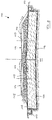
- the track system according to FIG. 2 corresponds in all essential points to the track system according to FIG. 1, but it is additionally provided here that a soundproof wall 25 is arranged and fastened on the essentially flat upper side 22b of the edge cap 22.
- the soundproof wall 25 is anchored in the edge cap 22 widened compared to the embodiment according to FIG. 1, while in the illustration on the right side according to FIG. 2 a foundation beam 12 is attached laterally on the outside of the edge cap 22 , in which a foundation sleeve 26 is provided for receiving soundproof wall cassettes or panels, which can optionally be used with a deep foundation 27 leading through the support plate 21.
- FIG. 7 shows an exemplary embodiment of an effective soundproof wall 25 in a steel design.
- the soundproof wall 25 consists of individual panels 25a and 25b to be attached to one another, the lower panels 25a being attached to the edge cap 22 via a base plate 28 or being held in the quiver foundations by supports.
- the panels 25a and 25b each have a plurality of inclined reflection surfaces 28a and 28b, the surface normal of which is essentially directed towards the ballast bed.
- the sound waves emanating from the sound source wheel-rail are reflected by the reflection surfaces 28a and 28b in the region of the absorbing ballast bed.
- the upper panel 25b has four smaller inclined reflecting surfaces 28b, while the lower panel 25a has two larger reflecting surfaces 25a, the reflecting surfaces 28a of the lower panels 25a being less inclined than the reflecting surfaces 28b of the upper panels 25b to in this way to adapt to the different angles of incidence of the sound waves emanating from the wheel-rail sound source onto the soundproof wall 25.
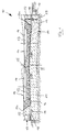
- the support plate 21 is designed as a continuous band-like concrete component, on the surface of which recesses 24 are provided which serve as transverse cable ducts which can be closed by means of a cover.
- the edge caps 22 consist of prefabricated concrete parts, which are lined up in the longitudinal direction of the track system and are arranged on the support plate 21 with the arrangement of a compensation layer 29. In the joint area between two prefabricated edge caps recesses are formed which form the transverse drain channels 18.
- FIG 4 shows a first embodiment of a longitudinally extending cable duct 17.
- the edge cap 22 is attached to the support plate 21 by arranging the compensating layer 29 such that between the side outer wall of the support plate 21 and the side outer wall of the Edge cap 22 an inwardly facing gradation is formed, on which the cable duct 17 is arranged with the interposition of a compensating layer 30.
- the cable duct 17 consists in a known manner of an upwardly open U-shaped channel body 17a, which can be closed by means of a cover 17b.
- the cable duct 17 can be fastened to the support plate 21 or the edge cap 22 in a manner not shown.
- the outside of the cable duct 17 is flush with the outside of the support plate 21.
- the cover 17b merges flush with the top 22b of the edge cap 22.
- the U-shaped channel body of the cable duct 17 is formed in one piece with the edge cap 22, again a cover 17b covering the cable duct 17 is provided, the surface of which is flush with the upper side 22b of the edge cap 22 completes.
- an outwardly projecting cantilever arm 22c is formed on the edge cap 22, onto which the U-shaped channel body 17a of the cable duct 17 is placed and fastened in a manner not shown.
- the channel body 17a can be closed with the cover 17b, the upper side of the cover 17b with the upper side 22b Edge cap 22 is flush.
- a projection 22d engaging behind the channel body 17a can be provided at the free end of the cantilever arm 22c, as a result of which the channel body 17a is held securely in the transverse direction.
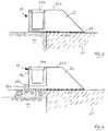
- the track system 110 shown in FIG. 8 comprises a two-track railway line with a solid support plate 120 in the form of a mass body which is supported on a substructure or the ground 111. Starting from the longitudinal center plane, the top and bottom of the mass body 120 have a sloping cross slope of 1:20 on both sides, so that a roof-shaped structure is achieved.
- the mass body 120 is completely embedded in the ground 111 with the interposition of an insulation mat 116 on its lower and its lateral surfaces. Cable channels 117 run laterally along the mass body 120 in a known manner.
- a ballast bed 115 is formed in a known manner on the top of the mass body 120 with the interposition of a sub-ballast mat 118, which carries sleepers 113 and rails 114 for a two-lane route.
- the course of the ballast bed 115 for a straight section of the route is shown with solid lines, while the course of the ballast bed for a curved route is indicated by dashed lines.
- the thickness of the mass body 120 which preferably replaces the formation protection layer and the frost protection layer, depends on the locally prevailing soil conditions and the relevant excitation frequencies and should be approximately in the range of one meter. As Figure 8 shows, the mass body 120 is laterally beyond the ballast bed 115, so that the train from the Pulse bed acting as a spring emitted impulses are completely transmitted to the mass body and from this after damping to the ground.
Landscapes
- Engineering & Computer Science (AREA)
- Architecture (AREA)
- Civil Engineering (AREA)
- Structural Engineering (AREA)
- Life Sciences & Earth Sciences (AREA)
- Sustainable Development (AREA)
- Railway Tracks (AREA)
- Train Traffic Observation, Control, And Security (AREA)
- Fittings On The Vehicle Exterior For Carrying Loads, And Devices For Holding Or Mounting Articles (AREA)
- Machines For Laying And Maintaining Railways (AREA)
- Platform Screen Doors And Railroad Systems (AREA)
Abstract
Description
Die Erfindung betrifft eine Gleisanlage für schienengebundene Fahrzeuge, insbesondere Eisenbahnen, mit einem Oberbau, der auf Schwellen gelagerte Schienen und ein die Schwellen unterstützendes Schotterbett aufweist, und mit einem den Oberbau tragenden Unterbau, der eine das Schotterbett tragende Tragplatte aus Beton aufweist, die auf einem Erdbauwerk aufgelagert ist.The invention relates to a track system for rail-bound vehicles, in particular railways, with a superstructure that has rails mounted on sleepers and a ballast bed that supports the sleepers, and with a substructure that supports the superstructure and that has a supporting plate made of concrete that supports the ballast bed and that on a Earth structure is supported.
Bei herkömmlichen Gleisanlagen wird als Oberbau üblicherweise der sogenannte Schotteroberbau verwendet, bei dem die Schwellen auf einem Schotterbett aufliegen. Das Gleis und das Schotterbett sind auf einen Unterbau aufgelagert, über den die vom Eisenbahnfahrzeug ausgeübten Kräfte in den Erdboden abgeleitet werden. Der Schotteroberbau hat sich bisher bewährt, da er eine hohe Flexibilität und Anpassungsfähigkeit besitzt und in relativ einfacher Weise instandzuhalten ist.In conventional track systems, the so-called ballast track is usually used as the superstructure, in which the sleepers rest on a ballast bed. The track and the ballast bed are supported on a substructure, via which the forces exerted by the railway vehicle are diverted into the ground. The ballast track has proven itself so far because it has a high degree of flexibility and adaptability and is relatively easy to maintain.
Es hat sich jedoch gezeigt, daß aufgrund höher werdender Achslasten und Fahrgeschwindigkeiten Schwingungen im Schotterbett auftreten, die zu einem Abbau der Reibung zwischen den Schottersteinen führen, was Schotterumlagerungen zur Folge hat, wodurch das Schotterbett sich in starkem Maße setzt und quer zur Gleisrichtung seitlich ausweicht. Dies bringt eine wesentliche Herabsetzung der Qualität der Gleisanlage mit sich und macht einen hohen Aufwand für die Instandhaltung erforderlich.However, it has been shown that vibrations occur in the ballast bed due to increasing axle loads and driving speeds, which lead to a reduction in the friction between the ballast stones, which causes ballast rearrangements As a result, the ballast bed settles to a large extent and dodges sideways across the direction of the track. This results in a significant reduction in the quality of the track system and requires a high level of maintenance.
Aus der DE 40 07 710 A1 ist es bei Tunnelbauwerken bekannt, den Schotteroberbau durch eine sogenannte feste Fahrbahn zu ersetzen, bei der das Gleis in oder auf einer festen Betonsohle der Tunnelröhre fest angebracht ist, wodurch eine stabile Positionierung des Gleises relativ zu der Betonsohle gewährleistet ist. Darüber hinaus können bei dieser Ausführung Querkräfte zuverlässig aufgenommen werden, da die Betonsohle seitlich durch die Tunnelwände gestützt ist. Ein Oberbau in Form einer festen Fahrbahn verfügt jedoch nur über eine sehr geringe, im Millimeter-Bereich liegende Korrigierbarkeit des Schienenstranges. Darüber hinaus ist eine sehr hohe Montagegenauigkeit erforderlich und auch an den Unterbau sind wesentlich höhere Anforderungen als bei dem Schotteroberbau zu stellen. Bei festem, im wesentlichen unverformbarem, homogenem Unterbau, wie er in Tunnelabschnitten oder auf längeren Brücken zu finden ist, lassen sich feste Fahrbahnen sinnvoll einsetzen. Wenn jedoch der Unterbau aus einem verformungsfreudigen Erdbauwerk besteht, sind aufwendige Zusatzmaßnahmen notwendig, um die Anforderungen an den Unterbau für eine feste Fahrbahn einhalten zu können. Auf diese Weise sind Gleisanlagen mit einem Oberbau in Form einer festen Fahrbahn häufig sehr teuer in der Herstellung.From DE 40 07 710 A1 it is known in tunnel structures to replace the ballast superstructure with a so-called fixed carriageway, in which the track is firmly attached in or on a solid concrete base of the tunnel tube, thereby ensuring a stable positioning of the track relative to the concrete base is. In addition, lateral forces can be reliably absorbed in this version, since the concrete base is supported laterally by the tunnel walls. A superstructure in the form of a solid track, however, has only a very small, millimeter range of correctability of the rail track. In addition, a very high level of assembly accuracy is required and the substructure also has to meet significantly higher requirements than the ballast superstructure. With solid, essentially non-deformable, homogeneous substructures, such as those found in tunnel sections or on longer bridges, solid carriageways can be used sensibly. However, if the substructure consists of a deformation-friendly earth structure, complex additional measures are necessary in order to be able to meet the requirements for the substructure for a solid carriageway. In this way, track systems with a superstructure in the form of a solid track are often very expensive to manufacture.
Aus der DE 41 00 881 A1 ist es bekannt, trogförmige Betonfertigteile zur Bildung einer Tragrinne aneinanderzureihen und in der Tragrinne ein Schotterbett anzuordnen, das die Gleise in bekannter Weise trägt und durch die Seitenteile der Tragrinne seitlich abgestützt ist. Die Betonfertigteile sind auf einem Erdbauwerk, d.h. dem bearbeiteten Erdboden aufgelegt, wobei unterhalb der Betonplatte eine Planumsschutzschicht und eine Frostschutzschicht ausgebildet sind.From DE 41 00 881 A1 it is known to line up trough-shaped prefabricated concrete parts to form a support channel and to arrange a ballast bed in the support channel, which supports the tracks in a known manner and through the side parts of the support channel are supported laterally. The precast concrete elements are placed on an earth structure, ie the processed soil, with a formation protection layer and a frost protection layer being formed below the concrete slab.
Erdbauwerke können im Laufe der Zeit relativ großen Verformungen unterliegen, was zu örtlichen Setzungen einzelner Betonfertigteile bzw. der Tragrinne führen kann. Um diesen Wirkungen vorzubeugen, ist eine sehr aufwendige und präzise Bearbeitung des Erdbodens notwendig, was jedoch sehr teuer ist. Darüber hinaus können insbesondere bei hohen Fahrgeschwindigkeiten der Züge Schwingungen und Erschütterungen auftreten. Die dynamischen Lasteinwirkungen des Eisenbahnbetriebes verursachen an dem tragenden Gleisrost und dem Schotterbett oder sonstigen Tragelementen Schwingungen, die über den Untergrund bzw. Unterbau weitergegeben werden und bereichsweise auf das angrenzende Umfeld wirken können. Bei naheliegender baulicher Nutzung und insbesondere bei ungünstigen Bodenverhältnissen lassen sich die zulässigen Werte für die Erschütterungen bei einer konventionellen Streckenausbildung mit einem Schotteroberbau oder einer sogenannten festen Fahrbahn häufig nicht einhalten. Dies kann insbesondere bei schwingungsempfindlichen Gebäuden zu Beeinträchtigungen oder Schäden führen. Gegebenenfalls ist sogar eine Aufgabe des Bauvorhabens oder eine Umlegung der Trasse erforderlich.Earthworks can be subject to relatively large deformations in the course of time, which can lead to local settlement of individual precast concrete elements or the support channel. In order to prevent these effects, a very complex and precise cultivation of the soil is necessary, which is very expensive. In addition, vibrations and shocks can occur, especially at high train speeds. The dynamic load effects of railway operations cause vibrations on the load-bearing track grate and the ballast bed or other supporting elements, which are passed on via the subsurface or substructure and can affect the surrounding area in some areas. With obvious structural use and in particular with unfavorable ground conditions, the permissible values for the vibrations can often not be adhered to in the case of conventional route training with a ballast track or a so-called solid roadway. This can lead to impairments or damage, especially in buildings that are sensitive to vibrations. It may even be necessary to abandon the construction project or relocate the route.
Der Erfindung liegt die Aufgabe zugrunde, eine Gleisanlage der genannten Art zu schaffen, die eine formstabile Halterung der Gleise sicherstellt, eine wesentlich verbesserte Korrigierbarkeit der Gleise nach Verformungen des Untergrundes oder Unterbaus bietet und eine Anpassung der Schwingungs- bzw. Erschütterungseigenschaften an die bauliche Gegebenheiten ermöglicht.The invention has for its object to provide a track system of the type mentioned, which ensures a dimensionally stable mounting of the tracks, a significantly improved correctability of the tracks after deformation of the ground or substructure and allows the vibration or vibration properties to be adapted to the structural conditions .
Diese Aufgabe wird bei einer Gleisanlage der genannten Art erfindungsgemäß dadurch gelöst, daß die Tragplatte als kontinuierliches, in Ortbeton hergestelltes Band ausgebildet ist und eine Stärke von mindestens 0,40 m aufweist.This object is achieved according to the invention in a track system of the type mentioned in that the support plate is designed as a continuous belt made of in-situ concrete and has a thickness of at least 0.40 m.
Die Schwingungs- und Erschütterungsprobleme lassen sich mit der erfindungsgemäßen massiven Tragplatte, die einen einheitlich, monolithisch wirkenden Körper großer Masse, einen sogenannten Massekörper, darstellt, nach dem Prinzip eines Masse-Feder-Systems lösen. Die Stärke der Tragplatte wird dabei entsprechend den baulichen Gegebenheiten so gewählt, daß ein wirksamer Schutz gegen Erschütterungen erreicht wird. Vorzugsweise werden die bei bekannten Gleisanlagen ebenfalls vorhandenen Planumsschutzschicht und Frostschutzschicht sowie gegebenenfalls Anteile des Schotterbettes durch ein geeignetes, dauerhaftes Bindemittel, insbesondere Zement, Kleber etc., zu dem Massekörper verbunden. Die von den fahrenden Zügen verursachten dynamischen Lasten, werden gewichts- und geschwindigkeitsabhängig über das als Feder wirkende Schotterbett als rasche Impulse in typischen Frequenzen an den Unterbau weitergeleitet. Die von dem Schotterbett übertragenen Impulse erregen den Massenkörper, der je nach Bemessung der Masse eine Schwingungs- und Frequenzänderung bewirkt. Auf diese Weise läßt sich ein auf die Eigenfrequenz der zu schützenden, angrenzenden Bebauung abgestimmtes Schwingungssystem schaffen, dessen Eigenfrequenz unter der Eigenfrequenz der schwingenden Teile der zu schützenden Bauwerke liegt. Somit können übermäßige Erschütterungen sowie unzulässiger Körperschall durch Anpassung an die örtlichen baulichen Gegebenheiten vermieden werden.The vibration and vibration problems can be solved with the solid support plate according to the invention, which represents a uniform, monolithically acting body of large mass, a so-called mass body, according to the principle of a mass-spring system. The strength of the support plate is chosen according to the structural conditions so that effective protection against vibrations is achieved. The formation protection layer and frost protection layer, which are also present in known track systems, and, if appropriate, portions of the ballast bed are preferably connected to the mass body by a suitable, permanent binder, in particular cement, adhesive, etc. The dynamic loads caused by the moving trains are passed on to the substructure as rapid impulses in typical frequencies, depending on the weight and speed, via the ballast bed acting as a spring. The impulses transmitted from the ballast bed excite the mass body, which, depending on the dimensioning of the mass, causes a vibration and frequency change. In this way, a vibration system can be created which is tuned to the natural frequency of the adjacent buildings to be protected and whose natural frequency lies below the natural frequency of the vibrating parts of the structures to be protected. Excessive vibrations and impermissible structure-borne noise can thus be avoided by adapting to the local structural conditions.
Der Massekörper sollte unterhalb des Schotteroberbaus als monolithisch wirkende, verbundene Masse hergestellt werden, wobei er vorzugsweise die Planumsschutzschicht und Frostschutzschicht ersetzt. Es ist jedoch auch möglich, die massive Tragplatte direkt auf die Planumsschutzschicht aufzulegen. Gegebenenfalls wird die Masse des Massekörpers durch anteiliges Verkleben des Schotters und klebende Verbindung dieses Schotterkörpers mit dem eigentlichen Massekörper vergrößert. Die im Masse-Feder-System vorhandene Federwirkung ergibt sich in diesem Fall aus den Federanteilen der Schienenzwischenlagen und des verbleibenden unverklebten Schotters. Vorzugsweise wird lediglich der Schotterrandbereich in den Böschungselementen, der sogenannte Vorkopfschotter, verklebt und eine geringe Oberflächenverklebung durchgeführt, um Schotterflug zu vermeiden. Falls eine weitere Vergrößerung der Masse über die Maximalstärke des aus Planumsschutzschicht und Frostschutzschicht bestehenden Schichtenpakets notwendig sein sollte, kann auch eine weitere Vergrößerung der Stärke des Massenkörpers durch Tieferlegung des Erdplanums erreicht werden.The mass body should be produced below the ballast superstructure as a monolithic, connected mass, whereby it preferably replaces the formation protection layer and frost protection layer. However, it is also possible to place the solid base plate directly on the formation protection layer. If necessary, the mass of the mass body is increased by partially bonding the ballast and adhesive bonding of this ballast body to the actual mass body. In this case, the spring effect in the mass-spring system results from the spring components of the rail intermediate layers and the remaining unglued ballast. Preferably, only the ballast edge area in the embankment elements, the so-called head ballast, is glued and a slight surface gluing is carried out in order to avoid ballast flight. If a further increase in the mass beyond the maximum thickness of the layer package consisting of the formation protection layer and the frost protection layer is necessary, a further increase in the thickness of the mass body can be achieved by lowering the earth level.
Es ist jedoch auch möglich, die konventionelle Funktion des Schotteroberbaus vollständig zu erhalten und diesen vom Massekörper zu trennen, was beispielsweise unterstützend auch durch Einlegen einer Unterschottermatte als Dämmung erreicht werden kann. Alternativ oder zusätzlich dazu kann auch der Massekörper mit entsprechenden Dämmatten umhüllt werden.However, it is also possible to fully maintain the conventional function of the ballast superstructure and to separate it from the mass body, which can also be achieved, for example, by inserting a sub-ballast mat as insulation. Alternatively or in addition, the mass body can also be covered with appropriate insulation mats.
Die Korrigierbarkeit der Gleisanlage bei eventuellen Verformungen des Unterbaus oder Untergrundes wird mittels konventioneller Bearbeitungsmaßnahmen des Schotterbetts in hohem Maße erreicht.The track system can be corrected in the event of any deformation of the substructure or subsoil by means of conventional processing measures for the ballast bed.
Als Grundmaterialien für den Massekörper eignen sich in kostengünstiger Weise beispielsweise die entsprechenden Tragschichten (Planumsschutzschicht, Frostschutzschicht), günstige rollige oder gebrochene Materialien, Recyclingmaterial ggf. mit Schwergewichtszugabe sowie in bestimmten Fällen auch eingekapselte kontaminierte Materialien. Die genannten Materialien werden mit einem Bindemittel, vorzugsweise Zement oder Bitumen, zu der monolithisch wirkenden Masse verbunden. Der Massekörper ist vorzugsweise unbewehrt, besitzt jedoch eine Dauerfestigkeit, die etwa im Bereich der Betonklassen B15 bis B25 liegt. Bereichsweise kann sowohl die Stärke durch Schwergewichtszusätze oder besondere Dämmaßnahmen reduziert und die Festigkeit beispielsweise durch Einlage von Bewehrung variiert bzw. erhöht werden.Suitable base materials for the mass body are, for example, the appropriate base layers (formation protection layer, frost protection layer), inexpensive rolled or broken materials, recycling material, possibly with the addition of heavy weights, and in certain cases also encapsulated contaminated materials. The materials mentioned are combined with a binder, preferably cement or bitumen, to form the monolithic compound. The mass body is preferably unreinforced, but has a fatigue strength that is approximately in the range of concrete classes B15 to B25. In some areas, the strength can be reduced by adding heavy weights or special insulation measures, and the strength can be varied or increased, for example, by inserting reinforcement.
Der Unterbau bzw. Untergrund hat im wesentlichen nur noch eine Tragfunktion für die massive Tragplatte zu übernehmen, ohne daß die Gefahr von Wasserdurchtritten besteht oder ein komplizierter Schichtenaufbau notwendig ist. Auf aufwendige Entwässerungsmaßnahmen kann dabei verzichtet werden. Durch die hohe Masse des Systems werden nach dem Prinzip eines Masse-Feder-Systems auch die dynamischen Belastungen und erzeugten Schwingungen in Frequenz und Intensität verändert und gedämpft, so daß hierauf gerichtete zusätzliche Maßnahmen weitgehend entfallen können. Die relativ große Stärke der Tragplatte, die größer als 0,4 m ist und etwa in einem Bereich von 0,4 m bis 1,4 m, und vorzugsweise bei etwa 0,7 m liegt, erfordert keine weiteren Frostschutzmaßnahmen und macht die bei anderen Systemen notwendige Planumsschutzschicht und/oder Frostschutzschicht überflüssig.The substructure or subsurface has essentially only a supporting function for the massive supporting plate without the risk of water penetration or a complicated layer structure being necessary. There is no need for complex drainage measures. Due to the high mass of the system, the dynamic loads and vibrations generated are changed and damped in frequency and intensity according to the principle of a mass-spring system, so that additional measures aimed at this can largely be dispensed with. The relatively large thickness of the support plate, which is greater than 0.4 m and approximately in a range from 0.4 m to 1.4 m, and preferably approximately 0.7 m, does not require any further frost protection measures and does the same for others Systems necessary formation protection layer and / or frost protection layer superfluous.
Die mit der erfindungsgemäßen Gleisanlage zu erzielenden Systemsteifigkeiten können variiert und an die Elastizitätswerte anderer Gleisanlagenarten angeglichen werden, so daß Systemübergänge auf andere Gleisanlagen speziell bei Brücken oder Tunneln keine Probleme aufwerfen und keine speziellen Konstruktionen erfordern.The system stiffness to be achieved with the track system according to the invention can be varied and adapted to the elasticity values of other types of track system, so that system transitions to other track systems, especially for bridges or tunnels, do not pose any problems and do not require any special designs.
In bevorzugter Ausgestaltung ist erfindungsgemäß vorgesehen, daß auf der Tragplatte außenseitige, nach oben vorstehende Randkappen angeordnet sind, die mit der Tragplatte einen das Schotterbett aufnehmenden rinnenförmigen Tragkörper bilden. Bei zweigleisigen Anlagen kann auf der Oberseite der Tragplatte zwischen den Gleisen auch eine nach oben vorstehende Mittelkappe ausgebildet sein, so daß jedem Gleis ein eigener rinnenförmiger Tragkörper zugeordnet ist. Auch bei der erfindungsgemäßen Gleisanlage sind die Schwellen in bzw. auf einem Schotterbett gelagert. Die Formbeständigkeit des Schotterbettes wird durch den oder die formhaltenden, rinnenförmigen Tragkörper gestützt, so daß übermäßige Setzungen des Schotterbettes oder dessen Ausweichen in Querrichtung vermieden werden können. Insbesondere können die aus dem Schienenbetrieb speziell bei hohen Geschwindigkeiten resultierenden Quer- bzw. Seitenkräfte durch die Randkappen und/oder die Mittelkappe aufgenommen werden. Der massive rinnenförmige Tragkörper ist sehr störungsunanfällig und bringt somit nur geringe Unterhaltskosten mit sich. Er wirkt über den gesamten Querschnitt der Gleisanlage und ermöglicht somit eine einfache Entwässerung. Es hat sich gezeigt, daß spezielle Anforderungen an den Unterbau oder hinsichtlich Schwingungsbelastungen bei der erfindungsgemäßen Gleisanlage nicht zu stellen sind. Die Randkappen und/oder die Mittelkappe können in ihrer Höhe variieren und bei Bedarf auf die maximale Querneigung der Gleise bzw. die auftretenden Seitenkräfte aufgerichtet sein.In a preferred embodiment, it is provided according to the invention that outer, upwardly projecting edge caps are arranged on the support plate, which, together with the support plate, form a channel-shaped support body which receives the ballast bed. In the case of double-track systems, an upwardly projecting central cap can also be formed on the top of the support plate between the tracks, so that each track has its own channel-shaped support body. In the track system according to the invention, the sleepers are stored in or on a ballast bed. The dimensional stability of the ballast bed is supported by the shape-retaining channel-shaped support body, so that excessive settling of the ballast bed or its evasion in the transverse direction can be avoided. In particular, the transverse or lateral forces resulting from the rail operation, especially at high speeds, can be absorbed by the edge caps and / or the center cap. The massive trough-shaped support body is very insusceptible to malfunctions and therefore only entails low maintenance costs. It acts across the entire cross-section of the track system and thus enables easy drainage. It has been shown that there are no special requirements for the substructure or with regard to vibration loads in the track system according to the invention. The height of the edge caps and / or the middle cap can vary and, if necessary, can be adjusted to the maximum cross slope of the tracks or the lateral forces that occur.
Da die Schwellen weiterhin in einem Schotterbett gelagert sind, kann die Schienenlage bei Bedarf in einfacher Weise korrigiert werden, wie es auch bei dem bekannten Schotteroberbau der Fall ist. Die massive Tragplatte wird unterhalb des Schotterbettes bestehender bzw. neu zu bauender Strecken auf Erdbauabschnitten, also unterhalb des Planums im Regelquerschnitt von Eisenbahnstrecken eingebaut und ersetzt dort vorzugsweise die Planumsschutzschicht und die Frostschutzschicht.Since the sleepers are still stored in a ballast bed, the rail position can be easily if necessary be corrected, as is the case with the known ballast track. The massive support plate is installed below the ballast bed of existing or new lines on earthwork sections, i.e. below the formation in the regular cross-section of railway lines and preferably replaces the formation protection layer and the frost protection layer there.
Die Randkappen und/oder die Mittelkappe können entweder an die Tragplatte einstückig angeformt oder auch als separate vorgefertigte Bauteile ausgebildet sein, die dann an der Tragplatte befestigt werden. Vorzugsweise wird zuerst die massive Tragplatte in Ortbeton als im wesentlichen kontinuierliches Band ausgebildet, woraufhin die Randkappen und/oder die Mittelkappe in Ortbetonausführung über eine formschlüssige Verbindung mit der Tragplatte verbunden werden. Es ist jedoch auch möglich, die als Fertigteil hergestellten Randkappen und/oder die Mittelkappe mit der Tragplatte zu verdübeln.The edge caps and / or the center cap can either be integrally formed on the support plate or can be designed as separate prefabricated components which are then attached to the support plate. Preferably, the solid support plate in in-situ concrete is formed as an essentially continuous band, whereupon the edge caps and / or the center cap in in-situ concrete design are connected to the support plate via a positive connection. However, it is also possible to dowel the edge caps produced as a finished part and / or the center cap with the support plate.
In bevorzugter Ausgestaltung der Erfindung ist vorgesehen, daß die innere Wandung der Randkappen und/oder der Mittelkappe derart geneigt ist, daß sie einen sich zum freien Ende hin verjüngenden Querschnitt besitzen. Die dem Gleis zugewandte Seite der Randkappen und/oder der Mittelkappe ist auf diese Weise in der Neigung so gestaltet, daß sie der Richtung der in dem Schotter entstehenden Kräfte möglichst flächig senkrecht entgegen wirken kann.In a preferred embodiment of the invention it is provided that the inner wall of the edge caps and / or the center cap is inclined in such a way that they have a cross section which tapers towards the free end. In this way, the side of the edge caps and / or the center cap facing the track is designed with an incline such that it can counteract the direction of the forces arising in the ballast vertically as far as possible.
Die Höhe der Randkappen und/oder der Mittelkappe bemißt sich nach der einzurichtenden Schotterbettstärke und dabei in der Geometrie des Gesamtquerschnitts derart, daß die Stützfunktion des Schotterbettes und die Querkraftaufnahme auch bei maximaler Überhöhung des Schienenstranges gewährleistet ist.The height of the edge caps and / or the center cap is measured according to the ballast bed thickness to be set up and in the geometry of the overall cross section in such a way that the support function of the ballast bed and the transverse force absorption is ensured even when the rail track is maximally raised.
In bevorzugter Ausgestaltung der Erfindung ist vorgesehen, daß das Schotterbett zur Erhöhung der Seitenstabilität des Schotters und für den Erschütterungsschutz in sich zumindest teilweise verklebt ist. Der verklebte Schotterkörper stellt in Verbindung mit der massiven Tragplatte und den seitlich stützenden Randkappen und/oder der Mittelkappe ein stabiles kräfte- und formbeständiges Gesamtsystem dar. Der verfestigte und querkraftbeständige verklebte Schotterkörper kann bei Setzungen des Untergrundes oder Unterbaus jederzeit nach mechanischem Aufbrechen neu geformt werden, so daß die Schienen in ihrer Lage und Ausrichtung nachjustiert werden können.In a preferred embodiment of the invention it is provided that the ballast bed is at least partially glued in itself to increase the lateral stability of the ballast and to protect against vibrations. The bonded ballast body, in conjunction with the solid support plate and the lateral supporting edge caps and / or the center cap, represents a stable, force-resistant and dimensionally stable overall system. so that the position and orientation of the rails can be readjusted.
Die Tragplatte und die Randkappen und/oder die Mittelkappe bestehen üblicherweise aus Beton, insbesondere B15 oder B25, wobei gegebenenfalls auch aufbereitete Zuschlagstoffe, Recyclingmaterial oder gegebenenfalls aufbereitete, eingekapselte und geeignete kontaminierte Materialien sowie andere Bindemittel als Zement, beispielsweise Bitumen, zur Herstellung der Tragplatte Verwendung finden können. Die Oberfläche der Tragplatte ist weitestgehend geschlossen und wasserableitend. Bei Bedarf kann zwischen dem Schotterbett und dem Tragkörper, d.h. der Tragplattenoberfläche und den inneren Wandungen der Randkappen und/oder der Mittelkappe eine Unterschottermatte eingelegt werden. Die Möglichkeit, nur Teilverklebungen des Schotterbettes vorzunehmen und Unterschottermatten unter und seitlich des Schotters einzulegen, eröffnet den Weg zu einem weichen, federnden Gesamtsystem mit variierbarer Federwirkung.The support plate and the edge caps and / or the middle cap usually consist of concrete, in particular B15 or B25, whereby optionally also prepared aggregates, recycling material or optionally prepared, encapsulated and suitable contaminated materials as well as binders other than cement, for example bitumen, are used for the production of the support plate can find. The surface of the support plate is largely closed and water-draining. If necessary, between the ballast bed and the supporting body, i.e. a sub-ballast mat is inserted into the support plate surface and the inner walls of the edge caps and / or the center cap. The option of only partially gluing the ballast bed and inserting ballast mats under and to the side of the ballast opens the way to a soft, springy overall system with variable spring action.
In Weichenbereichen werden lediglich die Randkappen und/oder die Mittelkappe im Bereich der durchlaufenden Schwellensätzen unterbrochen. Auf diese Weise ist ein unkompliziertes weichengeeignetes Gleisanlagensystem geschaffen.In the switch areas, only the edge caps and / or the center cap are interrupted in the area of the threshold sets running through. That way is a uncomplicated soft track system created.
Die massive, vorzugsweise einstückige Ausgestaltung der Tragplatte mit den seitlichen Randkappen und/oder der Mittelkappe und die damit erzielte Verbundwirkung kommt über den Querschnitt einer eingleisigen oder zweigleisigen Strecke einem entsprechenden Trog oder Kanal gleich, in dem das Schotterbett, das gegebenenfalls zu einem stabilen Schotterkörper verklebt ist, paßgenau und in formstabiler Weise aufgenommen ist. Bei einer zweigleisigen Strecke kann durch die Randkappen in Zusammenwirken mit der Mittelkappe eine entsprechende Trog- oder Kanalwirkung für jedes Gleis vorgesehen sein. In Weiterbildung der Erfindung ist vorgesehen, daß zumindest die Oberseite der Tragplatte eine Querneigung besitzt, die etwa 1:20 betragen sollte. Bei eingleisigen Strecken kann eine einseitige Neigung vorgesehen sein. Bei zweigleisigen Strecken sollte vorgesehen sein, daß die Oberseite der Tragplatte ausgehend von deren Längsmittelebene zu beiden Seiten eine abfallende Querneigung besitzt, so daß eine sogenannte Dachneigung verwirklicht ist. Die Querneigung der Oberseite der Tragplatte stellt eine Wasserableitung an der Tragplatte zu den Seiten der Gleisanlage sicher. Die lückenlose Überdeckung des Unterbaus durch die Tragplatte bietet für diesen einen sicheren Schutz vor eindringendem Wasser.The solid, preferably one-piece design of the support plate with the lateral edge caps and / or the center cap and the resulting composite effect is equivalent to a corresponding trough or channel across the cross section of a single-track or double-track section, in which the ballast bed, which possibly sticks to a stable ballast body is fit and recorded in a dimensionally stable manner. In the case of a double-track section, a corresponding trough or channel effect can be provided for each track through the edge caps in cooperation with the center cap. In a further development of the invention it is provided that at least the top of the support plate has a cross slope that should be about 1:20. A one-sided incline can be provided for single-track lines. In the case of double-track lines, it should be provided that the top of the support plate, starting from its longitudinal center plane, has a sloping transverse slope on both sides, so that a so-called roof slope is realized. The cross slope of the top of the support plate ensures water drainage on the support plate to the sides of the track system. The gapless covering of the substructure by the support plate offers reliable protection against water ingress.
Die massive Ausgestaltung der Tragplatte sowie der Randkappen bietet die Möglichkeit, auch andere streckenbegleitende Ausrüstungen wie beispielsweise Schallschutzwände, Kabelkanäle etc. an dem Tragkörper zu montieren. Insbesondere ist vorgesehen, daß auf der im wesentlichen ebenen Oberseite der Randkappen und/oder der Mittelkappe eine Schallschutzwand angeordnet ist. Die Randkappen und/oder die Mittelkappe können somit als Auflager für die Schallschutzwand dienen, wobei sie vorzugsweise mit Köchern für die Aufnahme der Halterungen der Schallschutzelemente ausgerüstet werden. Alternativ wird die Ausbildung der Köcher so vorgenommen, daß sie in die Tragplatte hinein oder bei Bedarf für eine Tiefgründung durch die Tragplatte hindurch reichen können. Um die Schallschutzwand in optimaler Entfernung von der Schiene bzw. der Schallquelle anordnen zu können, kann vorgesehen sein, die Randkappen und/oder die Mittelkappe gegebenenfalls zu verbreitern.The massive design of the support plate and the edge caps offers the possibility of also installing other equipment accompanying the route, such as soundproof walls, cable ducts, etc., on the support body. In particular, it is provided that a soundproofing wall is arranged on the essentially flat upper side of the edge caps and / or the center cap. The edge caps and / or the center cap can thus serve as supports for the soundproofing wall, wherein they are preferably equipped with quivers for receiving the holders of the soundproofing elements. Alternatively, the quiver is designed so that it can extend into the support plate or, if necessary, for a deep foundation through the support plate. In order to be able to arrange the soundproof wall at an optimal distance from the rail or the sound source, it can be provided that the edge caps and / or the center cap are widened if necessary.
Dabei können die Randkappen und/oder die Mittelkappe als Gründungsbalken für die Schallschutzwände ausgebildet sein, was den Vorteil mit sich bringt, daß die Randkappen und/oder die Mittelkappe mit relativ geringer Breite als kontinuierliches Bauteil über die gesamte Länge der Gleisanlage ausgebildet sein können, während sie in den Abschnitten, in denen die Anordnung einer Schallschutzwand notwendig ist, als Gründungsbalken die optimale Entfernung der Schallschutzwand von der Schiene sicherstellt. Auf diese Weise kann auch die Höhe der Schallschutzwand gering gehalten bzw. optimiert werden, was kostenmäßig vorteilhaft ist. Darüber hinaus kann die Schallschutzwand somit außerhalb des für die Züge freizuhaltenden Lichtraumprofils gehalten werden.The edge caps and / or the center cap can be designed as a foundation beam for the soundproof walls, which has the advantage that the edge caps and / or the center cap can be designed with a relatively small width as a continuous component over the entire length of the track system, while in the sections in which the arrangement of a soundproof wall is necessary, as a foundation beam, ensures the optimal removal of the soundproof wall from the rail. In this way, the height of the soundproof wall can also be kept low or optimized, which is advantageous in terms of cost. In addition, the soundproofing wall can thus be kept outside the clearance profile to be kept clear for the trains.
Die Schallschutzwand kann in bekannter Weise in Stahl- oder Betonausführung erstellt werden und besitzt vorzugsweise in bestimmten Abständen angeordnete Durchgangsmöglichkeiten.The soundproofing wall can be constructed in a known manner in steel or concrete design and preferably has passageways arranged at certain intervals.
Es ist bekannt, daß bei schienengebundenen Fahrzeugen die hauptsächliche Schallquelle im Rad-Schienen-Bereich liegt. Um eine gute Schallabsorption zu erreichen, ist in Weiterbildung der Erfindung vorgesehen, daß die Schallschutzwand auf der dem Gleis zugewandten Seite geneigte, die Schallwellen auf das Schotterbett richtende Reflexionsflächen besitzt. Die auf das Schotterbett gerichteten Schallwellen werden aufgrund der dortigen ungleichmäßig strukturierten Oberfläche ungerichtet bzw. in viele verschiedene Richtung reflektiert und auf diese Weise absorbiert. Vorzugsweise werden die Reflexionsflächen von einer Vielzahl geneigter Teilflächen gebildet, wobei diese unterschiedliche Neigungen besitzen können, um die von der Schallquelle Rad-Schiene ausgehenden Schallwellen wirkungsvoll auf das absorbierende Schotterbett richten zu können.It is known that the main sound source in rail-bound vehicles is in the wheel-rail area. In order to achieve good sound absorption, a further development of the invention provides that the soundproof wall on the side facing the track, which has sound surfaces that direct sound waves onto the ballast bed. The sound waves directed onto the ballast bed are non-directional due to the irregularly structured surface there or are reflected in many different directions and are thus absorbed. The reflection surfaces are preferably formed by a large number of inclined partial surfaces, these being able to have different inclinations in order to be able to effectively direct the sound waves emanating from the sound source wheel-rail onto the absorbing ballast bed.
Um das sich aufgrund der Querneigung der Oberseite der Tragplatte an einer oder an beiden Seiten des rinnenförmigen Tragkörpers ansammelnde Wasser abführen zu können, ist vorzugsweise vorgesehen, daß in den Randkappen und/oder der Mittelkappe querverlaufende Abflußkanäle ausgebildet sind, die über die Gleislänge in beliebigen Abständen angeordnet sind. Vorzugsweise sollten in der Tragplatte oder den Randkappen und/oder der Mittelkappe querverlaufende Kabelkanäle ausgebildet sein.In order to be able to remove the water that collects on one or both sides of the channel-shaped support body due to the transverse inclination of the top of the support plate, it is preferably provided that transverse drainage channels are formed in the edge caps and / or the center cap, which are spaced at arbitrary intervals along the track length are arranged. Preferably, transverse cable channels should be formed in the support plate or the edge caps and / or the center cap.
Die erfindungsgemäße Gleisanlage kann entweder mit einem bekannten, längs der Gleisanlage verlaufenden, erdverlegten Kabelkanal versehen sein, es ist jedoch auch möglich, die in Längsrichtung verlaufenden Kabelkanäle in den Tragkörper zu integrieren oder an diesem anzubringen. Die Kabelkanäle sind in bekannter Weise mittels einer Abdeckung verschlossen.The track system according to the invention can either be provided with a known, underground cable duct running along the track system, but it is also possible to integrate the cable ducts running in the longitudinal direction into the support body or to attach them to it. The cable ducts are closed in a known manner by means of a cover.
Vorzugsweise lagern die Randkappen auf der gleisabgewandten Seite den längsverlaufenden Kabelkanal bekannter Form, der entweder einstückig mit den Randkappen ausgebildet sein kann oder an diesen befestigt ist. Letzteres kann beispielsweise durch einen an der Randkappe ausgebildeten seitlich vorstehenden Kragarm erreicht werden, auf den der Kabelkanal aufgesetzt ist. Die Oberseiten der Randkappe und des zugeordneten Kabelkanals sollten zusammen eine durchgehende begehbare Fläche neben dem Gleiskörper bilden. Alternativ oder zusätzlich können die Kabelkanäle auch in die Mittelkappe integriert sein.Preferably, the edge caps on the side facing away from the track store the longitudinal cable duct of known shape, which can either be formed in one piece with the edge caps or is attached to them. The latter can be formed, for example, by one on the edge cap laterally projecting cantilever arm can be reached, on which the cable duct is placed. The tops of the edge cap and the associated cable duct should together form a continuous, accessible surface next to the track body. Alternatively or additionally, the cable ducts can also be integrated in the center cap.
Der Massekörper besitzt zumindest auf seiner Oberseite eine Neigung von vorzugsweise 1:20, was beispielsweise durch Ausgestaltung des Massekörpers mit einem parallelogramm-artigen Querschnitt erreicht werden kann. Bei eingleisigen Strecken ist eine einseitige Neigung ausreichend, während zur Erzielung einer ausreichenden Wasserableitung bei zweigleisigen Strecken eine Dachneigung vorgesehen sein sollte.The mass body has an inclination of preferably 1:20 at least on its upper side, which can be achieved, for example, by designing the mass body with a parallelogram-like cross section. A one-sided slope is sufficient for single-track lines, while a roof slope should be provided for achieving sufficient water drainage on double-track lines.
Weitere Einzelheiten und Merkmale der Erfindung sind aus der folgenden Beschreibung eines Ausführungsbeispiels unter Bezugnahme auf die Zeichnung ersichtlich. Es zeigen:
- Figur 1:
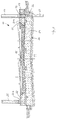
- den Querschnitt einer Gleisanlage,
- Figur 2:
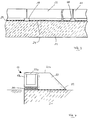
- einen Querschnitt einer modifizierten Gleisanlage,
- Figur 3:
- eine ausschnittsweise Seitenansicht einer Gleisanlage,
- Figur 4:
- eine erste Ausführungsform für einen Kabelkanal,
- Figur 5:
- eine zweite Ausführungsform für einen Kabelkanal,
- Figur 6:
- eine dritte Ausführungsform für einen Kabelkanal,
- Figur 7:
- ein Ausführungsbeispiel für eine Schallschutzwand und
- Figur 8:
- einen erfindungsgemäßen Massekörper.
- Figure 1:
- the cross section of a track system,
- Figure 2:
- a cross section of a modified track system,
- Figure 3:
- a partial side view of a track system,
- Figure 4:
- a first embodiment for a cable duct,
- Figure 5:
- a second embodiment for a cable duct,
- Figure 6:
- a third embodiment for a cable duct,
- Figure 7:
- an embodiment for a soundproof wall and
- Figure 8:
- a mass body according to the invention.
Gemäß Figur 1 umfaßt eine Gleisanlage 10 für eine zweigleisige Eisenbahnstrecke einen massiven Tragkörper 20, der eine auf einem Unterbau bzw. dem Erdboden 11 aufgelagerte massive Tragplatte 21 und daran angebrachte, seitliche, nach oben vorstehende Randkappen 22 umfaßt. Die Ober- und die Unterseite der Tragplatte 21 besitzen ausgehend von der Längsmittelebene zu beiden Seiten eine abfallende Querneigung von 1:20, so daß ein sogenannter dachförmiger Aufbau erreicht ist. Die Randkappen 22 stehen mit einem Vorsprung in einer Rechtecknut 19 der Tragplatte 21 in Eingriff, so daß eine formschlüssige Verbindung erreicht ist.According to FIG. 1, a
Wie auf der rechten Seite der Figur 1 zu sehen ist, kann die Randkappe 22 auch mittels einer Verdübelung 23 an der Tragplatte 21 befestigt sein.As can be seen on the right-hand side of FIG. 1, the
Die Tragplatte 21 bildet zusammen mit den Randkappen 22 eine trog- oder rinnenförmige Aufnahme für ein Schotterbett 15. In der rinnenförmigen Aufnahme ist zwischen dem Schotterbett 15 und der Oberseite der Tragplatte 21 sowie den dem Gleis zugewandten Wandungen 22a der Randkappen 22 eine Unterschottermatte 16 eingelegt. Das Schotterbett 15 ist gegebenenfalls zur Bildung eines in sich stabilen Schotterkörpers verklebt und lagert Schwellen 13 sowie Schienen 14 in bekannter Weise. Wie in Figur 1 auf der rechten Seite gestrichelt angedeutet ist, kann das Gleis und somit das Schotterbett insbesondere bei gekrümmter Streckenführung eine Querneigung besitzen. In diesem Fall kann die entsprechende Randkappe zur Stützung des Schotterbettes auf der erhöhten Seite ebenfalls erhöht sein.The
Um das sich in dem Randbereichen der rinnenförmigen Aufnahme aufgrund der Querneigung ansammelnde Niederschlagswasser abführen zu können, ist beidseitig im Übergangsbereich zwischen der Tragplatte 21 und den Randkappen 22 ein querverlaufender Abflußkanal 18 ausgebildet, der zuverlässig für eine Entwässerung sorgt.In order to be able to drain the rainwater accumulating in the edge areas of the channel-shaped receptacle due to the transverse inclination, a transversely extending
Auf der rechten Seite der Figur 1 ist ein längs der Gleisanlage verlaufender Kabelkanal 17 dargestellt, der in herkömmlicher Weise in das Erdreich eingegraben und mittels einer Abdeckung verschlossen ist. Alternativ kann jedoch auch der Kabelkanal 17 in die Randkappe 22 integriert sein, wie auf der linken Seite der Figur 1 dargestellt ist und später im einzelnen beschrieben wird.On the right-hand side of FIG. 1, a
Die Gleisanlage gemäß Figur 2 entspricht in allen wesentlichen Punkten der Gleisanlage gemäß Figur 1, jedoch ist hierbei zusätzlich vorgesehen, daß auf der im wesentlichen ebenen Oberseite 22b der Randkappe 22 eine Schallschutzwand 25 angeordnet und befestigt ist. Gemäß der Darstellung auf der linken Seite in Figur 2 ist die Schallschutzwand 25 in der gegenüber der Ausführungsform gemäß Figur 1 verbreiterten Randkappe 22 verankert, während in der Darstellung auf der rechten Seite gemäß Figur 2 seitlich auf der Außenseite der Randkappe 22 ein Gründungsbalken 12 angebracht ist, in dem ein Gründungsköcher 26 zur Aufnahme von Schallschutzwandkassetten oder -paneelen vorgesehen ist, der wahlweise mit einer durch die Tragplatte 21 hindurchführenden Tiefgründung 27 verwendet werden kann.The track system according to FIG. 2 corresponds in all essential points to the track system according to FIG. 1, but it is additionally provided here that a
In Figur 7 ist ein Ausführungsbeispiel für eine wirkungsvolle Schallschutzwand 25 in Stahlausführung dargestellt. Die Schallschutzwand 25 besteht aus aufeinander zu befestigenden Einzelpaneelen 25a und 25b, wobei die untere Paneele 25a über eine Fußplatte 28 auf der Randkappe 22 befestigt oder durch Träger in den Köcherfundamenten gehalten ist.FIG. 7 shows an exemplary embodiment of an effective
Auf der inneren, dem Gleiskörper zugewandten Oberfläche besitzen die Paneelen 25a und 25b jeweils mehrere geneigte Reflexionsflächen 28a und 28b, deren Flächennormale im wesentlichen auf das Schotterbett gerichtet ist. Die von der Schallquelle Rad-Schiene ausgehenden Schallwellen werden von den Reflexionsflächen 28a und 28b in den Bereich des absorbierenden Schotterbetts reflektiert. Wie Figur 7 zeigt, besitzt die obere Paneele 25b vier kleinere geneigte Reflexionsflächen 28b, während die untere Paneele 25a zwei größere Reflexionsflächen 25a aufweist, wobei die Reflexionsflächen 28a der unteren Paneele 25a eine geringere Neigung als die Reflexionsflächen 28b der oberen Paneele 25b besitzen, um auf diese Weise eine Anpassung an die unterschiedlichen Einfallswinkel der von der Rad-Schiene-Schallquelle ausgehenden Schallwellen auf die Schallschutzwand 25 zu erreichen.On the inner surface facing the track body, the
Aus der in Figur 3 dargestellten Seitenansicht der Gleisanlage ist zu entnehmen, daß die Tragplatte 21 als kontinuierliches bandartiges Betonbauteil ausgebildet ist, an dessen Oberfläche Aussparungen 24 vorgesehen sind, die als quer- verlaufende Kabelkanäle dienen, die mittels einer Abdeckung verschlossen sein können. Die Randkappen 22 bestehen aus Betonfertigteilen, die in Längsrichtung der Gleisanlage aneinandergereiht und unter Anordnung einer Ausgleichslage 29 auf der Tragplatte 21 angeordnet sind. Im Stoßbereich zwischen zwei Randkappen-Fertigteilen sind Ausnehmungen ausgebildet, die die querverlaufenden Abflußkanäle 18 bilden.From the side view of the track system shown in Figure 3 it can be seen that the
Figur 4 zeigt ein erstes Ausführungsbeispiel für einen in Längsrichtung der Gleisanlage verlaufenden Kabelkanal 17. Gemäß diesem Ausführungsbeispiel ist die Randkappe 22 unter Anordnung der Ausgleichslage 29 auf der Tragplatte 21 derart befestigt, daß zwischen der seitlich äußeren Wand der Tragplatte 21 und der seitlich äußeren Wand der Randkappe 22 eine nach innen weisende Abstufung gebildet ist, auf der der Kabelkanal 17 unter Zwischenschaltung einer Ausgleichsschicht 30 angeordnet ist. Der Kabelkanal 17 besteht in bekannter Weise aus einem nach oben offenen U-förmigen Rinnenkörper 17a, der mittels eines Deckels 17b verschließbar ist. Der Kabelkanal 17 kann in nicht näher dargestellter Weise an der Tragplatte 21 oder der Randkappe 22 befestigt sein. Im montierten Zustand schließt die Außenseite des Kabelkanals 17 bündig mit der Außenseite der Tragplatte 21 ab. Darüber hinaus geht der Deckel 17b bündig in die Oberseite 22b der Randkappe 22 über.Figure 4 shows a first embodiment of a longitudinally extending
Gemäß einem weiteren Ausführungsbeispiel, das in Figur 5 dargestellt ist, ist der U-förmige Rinnenkörper des Kabelkanals 17 einstückig mit der Randkappe 22 ausgebildet, wobei wiederum ein den Kabelkanal 17 abdeckender Deckel 17b vorgesehen ist, dessen Oberfläche bündig mit der Oberseite 22b der Randkappe 22 abschließt.According to a further exemplary embodiment, which is shown in FIG. 5, the U-shaped channel body of the
Gemäß Figur 6 ist an der Randkappe 22 ein nach außen vorstehender Kragarm 22c angeformt, auf den der U-förmige Rinnenkörper 17a des Kabelkanals 17 aufgesetzt und in nicht dargestellter Weise befestigt ist. Der Rinnenkörper 17a ist mit dem Deckel 17b verschließbar, wobei die Oberseite des Deckels 17b mit der Oberseite 22b der Randkappe 22 bündig abschließt. Wie in Fig. 6 gestrichelt angedeutet ist, kann am freien Ende des Kragarms 22c ein den Rinnenkörper 17a hintergreifender Vorsprung 22d vorgesehen sein, wodurch der Rinnenkörper 17a in Querrichtung sicher gehalten ist.According to FIG. 6, an outwardly projecting
Die in Figur 8 gezeigte Gleisanlage 110 umfaßt eine zweigleisige Eisenbahnstrecke mit einer massiven Tragplatte 120 in Form eines Massekörpers, der auf einem Unterbau bzw. dem Erdboden 111 aufgelagert ist. Die Ober- und Unterseite des Massekörpers 120 besitzen ausgehend von der Längsmittelebene zu beiden Seiten eine abfallende Querneigung von 1:20, so daß ein dachförmiger Aufbau erreicht ist. Der Massekörper 120 ist unter Zwischenschaltung einer Dämmatte 116 auf seiner unteren und seinen seitlichen Flächen vollständig in den Erdboden 111 eingebettet. Seitlich längs des Massekörpers 120 verlaufen in bekannter Weise Kabelkanäle 117.The
Auf der Oberseite des Massekörpers 120 ist unter Zwischenschaltung einer Unterschottermatte 118 ein Schotterbett 115 in bekannter Weise ausgebildet, das Schwellen 113 sowie Schienen 114 für eine zweispurige Strecke trägt. Mit durchgezogenen Linien ist der Verlauf des Schotterbettes 115 für einen geraden Streckenabschnitt dargestellt, während gestrichelt der Verlauf des Schotterbettes für eine gekrümmte Streckenführung angedeutet ist.A
Die Stärke des Massekörpers 120, der vorzugsweise die Planumsschutzschicht und die Frostschutzschicht ersetzt, ist von den örtlich überwiegend vorhandenen Bodenverhältnissen und den maßgebenden Erregerfrequenzen abhängig und sollte etwa im Bereich von einem Meter liegen. Wie Figur 8 zeigt, ist der Massekörper 120 seitlich über das Schotterbett 115 hinausgeführt, so daß die von dem Zug auf das als Feder wirkende Schotterbett abgegebenen Impulse vollständig in den Massekörper und von diesem nach erfolgter Dämpfung in den Erdboden übertragen werden.The thickness of the
Claims (20)
Priority Applications (1)
| Application Number | Priority Date | Filing Date | Title |
|---|---|---|---|
| DE29622835U DE29622835U1 (en) | 1995-01-10 | 1996-01-09 | Track system for rail-bound vehicles |
Applications Claiming Priority (2)
| Application Number | Priority Date | Filing Date | Title |
|---|---|---|---|
| DE19500443 | 1995-01-10 | ||
| DE19500443A DE19500443A1 (en) | 1995-01-10 | 1995-01-10 | Track system for rail-bound vehicles |
Publications (2)
| Publication Number | Publication Date |
|---|---|
| EP0722012A1 true EP0722012A1 (en) | 1996-07-17 |
| EP0722012B1 EP0722012B1 (en) | 1998-04-29 |
Family
ID=7751180
Family Applications (1)
| Application Number | Title | Priority Date | Filing Date |
|---|---|---|---|
| EP96100188A Expired - Lifetime EP0722012B1 (en) | 1995-01-10 | 1996-01-09 | Track for rail-bound vehicles |
Country Status (4)
| Country | Link |
|---|---|
| EP (1) | EP0722012B1 (en) |
| AT (1) | ATE165637T1 (en) |
| DE (2) | DE19500443A1 (en) |
| DK (1) | DK0722012T3 (en) |
Cited By (8)
| Publication number | Priority date | Publication date | Assignee | Title |
|---|---|---|---|---|
| US6913717B2 (en) * | 2001-12-05 | 2005-07-05 | Alstom | Method of constructing a rail track in which a concrete track slab is produced and rail track anchor members are inserted into the track slab |
| AT512523B1 (en) * | 2011-11-22 | 2013-09-15 | Art Asamer Rubber Technology Gmbh | Foundationless noise protection device |
| WO2014006144A1 (en) * | 2012-07-04 | 2014-01-09 | Hering Bau Gmbh & Co. Kg | Acoustic shielding unit and structure thereof |
| AT514307A1 (en) * | 2013-05-02 | 2014-11-15 | Kossik Roman | Support for solid elements in driveways with ballast superstructure on elastic, bituminous bonded base course |
| CN108842522A (en) * | 2018-06-06 | 2018-11-20 | 广州地铁设计研究院有限公司 | A kind of prefabricated floating plate track of adjustable damping grade |
| AT16231U1 (en) * | 2013-11-08 | 2019-04-15 | Jozsef Szabo | Structure arrangement for the stabilization of linear earthworks |
| CN110761127A (en) * | 2019-12-04 | 2020-02-07 | 中铁二院工程集团有限责任公司 | Rock foundation existing high-speed railway embankment force balance side width structure and construction method |
| CN113062148A (en) * | 2021-03-30 | 2021-07-02 | 武汉理工大学 | High-speed railway bed surface layer thickness flexibility design method |
Families Citing this family (10)
| Publication number | Priority date | Publication date | Assignee | Title |
|---|---|---|---|---|
| DE19741020A1 (en) * | 1997-09-18 | 1999-04-08 | Georg Groetz | Track system for rail-bound vehicles |
| DE19831404C2 (en) * | 1998-07-15 | 2001-10-11 | Vogel Bau Gmbh | Track system for rail-bound vehicles |
| DE19841831A1 (en) * | 1998-09-12 | 2000-05-04 | Vogel Bau Gmbh | Rail track assembly has a lower carrier plate of a material with a bitumen bonding to support the ballast bed and the sleepers with their rails for reduced costs and a longer life for the carrier |
| DE20005558U1 (en) | 2000-03-24 | 2000-05-25 | Grötz, Georg, 76597 Loffenau | Track system for rail-bound vehicles |
| DE20120610U1 (en) | 2001-12-20 | 2002-02-28 | Grötz, Georg, 76597 Loffenau | Track ballast for a ballast bed of a track route, especially for railways |
| DE102004002862A1 (en) * | 2004-01-19 | 2005-08-25 | Edilon Gmbh | Track body used for railways near built-up areas, e.g. suburban railways or tramways, comprises a body with two parallel grooves for rails, mini protection walls parallel to the grooves, and a damping agent between the mini protection walls |
| DE102008002836A1 (en) | 2008-04-30 | 2009-11-05 | Msb-Management Gmbh | Low noise barrier on tracks |
| DE102008044675B4 (en) | 2008-08-28 | 2017-02-23 | Johann Walthelm Gmbh | Vibration protection for a track superstructure and manufacturing process for it |
| CN102787532A (en) * | 2012-09-02 | 2012-11-21 | 中铁二院工程集团有限责任公司 | High-speed railroad shoulder and drainage structure |
| CN105735055B (en) * | 2016-02-04 | 2018-05-04 | 陈森 | Imbibition drainage |
Citations (6)
| Publication number | Priority date | Publication date | Assignee | Title |
|---|---|---|---|---|
| US1633211A (en) * | 1924-06-30 | 1927-06-21 | Edwin A Jenks | Roadway embankment |
| DE1243225B (en) * | 1964-05-21 | 1967-06-29 | Gruenzweig & Hartmann | Sound and vibration isolating ballast bedding |
| US3587964A (en) * | 1969-04-18 | 1971-06-28 | Meadows W R Inc | Protective course for bridge deck |
| DE2751346A1 (en) * | 1977-11-17 | 1979-05-23 | Phoenix Ag | Railway track resonance and vibration insulating mat - has interlocking top lengthways engaging ribs and parallel bottom support ribs |
| DE4100881A1 (en) * | 1991-01-14 | 1992-07-16 | Cronau Heinrich Gmbh | Permanent way for railway high speed trains - consists of precast concrete trough sections laid end on end and filled with ballast bed |
| DE4401260C1 (en) * | 1994-01-18 | 1995-05-18 | Heitkamp Gmbh Bau | Permanent waxy construction for railway tracks, esp. for high speed |
Family Cites Families (1)
| Publication number | Priority date | Publication date | Assignee | Title |
|---|---|---|---|---|
| DE4007710C2 (en) * | 1990-03-10 | 1995-04-06 | Dyckerhoff & Widmann Ag | Process for manufacturing a railway superstructure in a tunnel |
-
1995
- 1995-01-10 DE DE19500443A patent/DE19500443A1/en not_active Ceased
-
1996
- 1996-01-09 EP EP96100188A patent/EP0722012B1/en not_active Expired - Lifetime
- 1996-01-09 DE DE59600164T patent/DE59600164D1/en not_active Expired - Lifetime
- 1996-01-09 DK DK96100188T patent/DK0722012T3/en active
- 1996-01-09 AT AT96100188T patent/ATE165637T1/en not_active IP Right Cessation
Patent Citations (6)
| Publication number | Priority date | Publication date | Assignee | Title |
|---|---|---|---|---|
| US1633211A (en) * | 1924-06-30 | 1927-06-21 | Edwin A Jenks | Roadway embankment |
| DE1243225B (en) * | 1964-05-21 | 1967-06-29 | Gruenzweig & Hartmann | Sound and vibration isolating ballast bedding |
| US3587964A (en) * | 1969-04-18 | 1971-06-28 | Meadows W R Inc | Protective course for bridge deck |
| DE2751346A1 (en) * | 1977-11-17 | 1979-05-23 | Phoenix Ag | Railway track resonance and vibration insulating mat - has interlocking top lengthways engaging ribs and parallel bottom support ribs |
| DE4100881A1 (en) * | 1991-01-14 | 1992-07-16 | Cronau Heinrich Gmbh | Permanent way for railway high speed trains - consists of precast concrete trough sections laid end on end and filled with ballast bed |
| DE4401260C1 (en) * | 1994-01-18 | 1995-05-18 | Heitkamp Gmbh Bau | Permanent waxy construction for railway tracks, esp. for high speed |
Cited By (12)
| Publication number | Priority date | Publication date | Assignee | Title |
|---|---|---|---|---|
| US6913717B2 (en) * | 2001-12-05 | 2005-07-05 | Alstom | Method of constructing a rail track in which a concrete track slab is produced and rail track anchor members are inserted into the track slab |
| AT512523B1 (en) * | 2011-11-22 | 2013-09-15 | Art Asamer Rubber Technology Gmbh | Foundationless noise protection device |
| AT512523A4 (en) * | 2011-11-22 | 2013-09-15 | Art Asamer Rubber Technology Gmbh | Foundationless noise protection device |
| WO2014006144A1 (en) * | 2012-07-04 | 2014-01-09 | Hering Bau Gmbh & Co. Kg | Acoustic shielding unit and structure thereof |
| AT514307A1 (en) * | 2013-05-02 | 2014-11-15 | Kossik Roman | Support for solid elements in driveways with ballast superstructure on elastic, bituminous bonded base course |
| AT514307B1 (en) * | 2013-05-02 | 2016-08-15 | Kossik Roman | Support for solid elements in driveways with ballast superstructure on elastic, bituminous bonded base course |
| AT16231U1 (en) * | 2013-11-08 | 2019-04-15 | Jozsef Szabo | Structure arrangement for the stabilization of linear earthworks |
| AT16231U8 (en) * | 2013-11-08 | 2019-06-15 | Jozsef Szabo | Structure arrangement for the stabilization of linear earthworks |
| CN108842522A (en) * | 2018-06-06 | 2018-11-20 | 广州地铁设计研究院有限公司 | A kind of prefabricated floating plate track of adjustable damping grade |
| CN108842522B (en) * | 2018-06-06 | 2023-11-24 | 广州地铁设计研究院股份有限公司 | Prefabricated floating slab track with adjustable vibration reduction level |
| CN110761127A (en) * | 2019-12-04 | 2020-02-07 | 中铁二院工程集团有限责任公司 | Rock foundation existing high-speed railway embankment force balance side width structure and construction method |
| CN113062148A (en) * | 2021-03-30 | 2021-07-02 | 武汉理工大学 | High-speed railway bed surface layer thickness flexibility design method |
Also Published As
| Publication number | Publication date |
|---|---|
| DE19500443A1 (en) | 1996-07-18 |
| DE59600164D1 (en) | 1998-06-04 |
| ATE165637T1 (en) | 1998-05-15 |
| EP0722012B1 (en) | 1998-04-29 |
| DK0722012T3 (en) | 1999-02-15 |
Similar Documents
| Publication | Publication Date | Title |
|---|---|---|
| EP0722012B1 (en) | Track for rail-bound vehicles | |
| EP0937181B1 (en) | Railroad substructure | |
| EP1825059B1 (en) | Concrete track for rail vehicles | |
| DE102008002836A1 (en) | Low noise barrier on tracks | |
| EP1836352B1 (en) | Fixed track bed for rail vehicles | |
| WO2009121323A1 (en) | Fixed track for rail vehicles | |
| DE19919255B4 (en) | tunnel track | |
| EP0547082B1 (en) | Foundation for railway track | |
| DD284066A5 (en) | ARRANGEMENT FOR TRAINING OF RAILWAY BUILDINGS | |
| DE3429413A1 (en) | Height-adjustable and laterally adjustable superstructure for rail lines with separable covering of sleepers on a jointless plate | |
| EP1258563B1 (en) | Ballastless railway track with elastically supported sound absorber elements | |
| EP1331310B1 (en) | Elastical support system for a grooved rail | |
| AT512523B1 (en) | Foundationless noise protection device | |
| DE29622835U1 (en) | Track system for rail-bound vehicles | |
| AT370461B (en) | METHOD FOR PRODUCING AN ELASTICALLY BEARED TROUGH FROM REINFORCED CONCRETE AS A STRUCTURAL STRUCTURE CONSTRUCTING SOURCE FOR THE CONSTRUCTION OF A RAILWAY RAILWAY, IN PARTICULAR ON DOWNTOWN TUNNEL RUNS | |
| DE19625249C2 (en) | Positionally stable track body made of precast concrete parts and use of precast concrete parts for this track body | |
| DE60106552T2 (en) | Track for a rail vehicle and a device containing such a track | |
| DE19831404C2 (en) | Track system for rail-bound vehicles | |
| DE19706542B4 (en) | roadway | |
| EP1182294B1 (en) | Railway track and method for making a railway track | |
| DE20216387U1 (en) | Track system for rail-bound vehicles | |
| DE102004002862A1 (en) | Track body used for railways near built-up areas, e.g. suburban railways or tramways, comprises a body with two parallel grooves for rails, mini protection walls parallel to the grooves, and a damping agent between the mini protection walls | |
| EP0832325A1 (en) | Low-noise track element | |
| DE19841831A1 (en) | Rail track assembly has a lower carrier plate of a material with a bitumen bonding to support the ballast bed and the sleepers with their rails for reduced costs and a longer life for the carrier | |
| DE19541491A1 (en) | Fixed track for rail-bound traffic |
Legal Events
| Date | Code | Title | Description |
|---|---|---|---|
| PUAI | Public reference made under article 153(3) epc to a published international application that has entered the european phase |
Free format text: ORIGINAL CODE: 0009012 |
|
| AK | Designated contracting states |
Kind code of ref document: A1 Designated state(s): AT BE CH DE DK FR IT LI LU NL |
|
| 17P | Request for examination filed |
Effective date: 19960725 |
|
| GRAG | Despatch of communication of intention to grant |
Free format text: ORIGINAL CODE: EPIDOS AGRA |
|
| GRAG | Despatch of communication of intention to grant |
Free format text: ORIGINAL CODE: EPIDOS AGRA |
|
| GRAH | Despatch of communication of intention to grant a patent |
Free format text: ORIGINAL CODE: EPIDOS IGRA |
|
| 17Q | First examination report despatched |
Effective date: 19971017 |
|
| GRAH | Despatch of communication of intention to grant a patent |
Free format text: ORIGINAL CODE: EPIDOS IGRA |
|
| GRAA | (expected) grant |
Free format text: ORIGINAL CODE: 0009210 |
|
| AK | Designated contracting states |
Kind code of ref document: B1 Designated state(s): AT BE CH DE DK FR IT LI LU NL |
|
| REF | Corresponds to: |
Ref document number: 165637 Country of ref document: AT Date of ref document: 19980515 Kind code of ref document: T |
|
| REG | Reference to a national code |
Ref country code: CH Ref legal event code: EP |
|
| ITF | It: translation for a ep patent filed | ||
| REF | Corresponds to: |
Ref document number: 59600164 Country of ref document: DE Date of ref document: 19980604 |
|
| REG | Reference to a national code |
Ref country code: CH Ref legal event code: NV Representative=s name: TROESCH SCHEIDEGGER WERNER AG |
|
| ET | Fr: translation filed | ||
| PLBQ | Unpublished change to opponent data |
Free format text: ORIGINAL CODE: EPIDOS OPPO |
|
| PLBI | Opposition filed |
Free format text: ORIGINAL CODE: 0009260 |
|
| REG | Reference to a national code |
Ref country code: DK Ref legal event code: T3 |
|
| PLBF | Reply of patent proprietor to notice(s) of opposition |
Free format text: ORIGINAL CODE: EPIDOS OBSO |
|
| 26 | Opposition filed |
Opponent name: SCHWEIZ. BUNDESBAHNEN SBB Effective date: 19990128 |
|
| NLR1 | Nl: opposition has been filed with the epo |
Opponent name: SCHWEIZ. BUNDESBAHNEN SBBB AUDIREKTION |
|
| PLBF | Reply of patent proprietor to notice(s) of opposition |
Free format text: ORIGINAL CODE: EPIDOS OBSO |
|
| PLBF | Reply of patent proprietor to notice(s) of opposition |
Free format text: ORIGINAL CODE: EPIDOS OBSO |
|
| PLBL | Opposition procedure terminated |
Free format text: ORIGINAL CODE: EPIDOS OPPC |
|
| PLBM | Termination of opposition procedure: date of legal effect published |
Free format text: ORIGINAL CODE: 0009276 |
|
| STAA | Information on the status of an ep patent application or granted ep patent |
Free format text: STATUS: OPPOSITION PROCEDURE CLOSED |
|
| 27C | Opposition proceedings terminated |
Effective date: 20000102 |
|
| NLR2 | Nl: decision of opposition | ||
| PGFP | Annual fee paid to national office [announced via postgrant information from national office to epo] |
Ref country code: AT Payment date: 20060113 Year of fee payment: 11 |
|
| PGFP | Annual fee paid to national office [announced via postgrant information from national office to epo] |
Ref country code: NL Payment date: 20060119 Year of fee payment: 11 |
|
| PGFP | Annual fee paid to national office [announced via postgrant information from national office to epo] |
Ref country code: DK Payment date: 20060125 Year of fee payment: 11 Ref country code: BE Payment date: 20060125 Year of fee payment: 11 |
|
| PGFP | Annual fee paid to national office [announced via postgrant information from national office to epo] |
Ref country code: LU Payment date: 20060203 Year of fee payment: 11 |
|
| PGFP | Annual fee paid to national office [announced via postgrant information from national office to epo] |
Ref country code: CH Payment date: 20060327 Year of fee payment: 11 |
|
| PG25 | Lapsed in a contracting state [announced via postgrant information from national office to epo] |
Ref country code: LI Free format text: LAPSE BECAUSE OF NON-PAYMENT OF DUE FEES Effective date: 20070131 Ref country code: CH Free format text: LAPSE BECAUSE OF NON-PAYMENT OF DUE FEES Effective date: 20070131 |
|
| REG | Reference to a national code |
Ref country code: CH Ref legal event code: PL |
|
| NLV4 | Nl: lapsed or anulled due to non-payment of the annual fee |
Effective date: 20070801 |
|
| REG | Reference to a national code |
Ref country code: DK Ref legal event code: EBP |
|
| PG25 | Lapsed in a contracting state [announced via postgrant information from national office to epo] |
Ref country code: AT Free format text: LAPSE BECAUSE OF NON-PAYMENT OF DUE FEES Effective date: 20070109 |
|
| BERE | Be: lapsed |
Owner name: *GROTZ GEORG Effective date: 20070131 |
|
| PG25 | Lapsed in a contracting state [announced via postgrant information from national office to epo] |
Ref country code: BE Free format text: LAPSE BECAUSE OF NON-PAYMENT OF DUE FEES Effective date: 20070131 |
|
| PG25 | Lapsed in a contracting state [announced via postgrant information from national office to epo] |
Ref country code: NL Free format text: LAPSE BECAUSE OF NON-PAYMENT OF DUE FEES Effective date: 20070801 Ref country code: DK Free format text: LAPSE BECAUSE OF NON-PAYMENT OF DUE FEES Effective date: 20070131 |
|
| PG25 | Lapsed in a contracting state [announced via postgrant information from national office to epo] |
Ref country code: LU Free format text: LAPSE BECAUSE OF NON-PAYMENT OF DUE FEES Effective date: 20070109 |
|
| PGFP | Annual fee paid to national office [announced via postgrant information from national office to epo] |
Ref country code: IT Payment date: 20110126 Year of fee payment: 16 Ref country code: FR Payment date: 20110209 Year of fee payment: 16 |
|
| REG | Reference to a national code |
Ref country code: FR Ref legal event code: ST Effective date: 20120928 |
|
| PG25 | Lapsed in a contracting state [announced via postgrant information from national office to epo] |
Ref country code: IT Free format text: LAPSE BECAUSE OF NON-PAYMENT OF DUE FEES Effective date: 20120109 |
|
| PG25 | Lapsed in a contracting state [announced via postgrant information from national office to epo] |
Ref country code: FR Free format text: LAPSE BECAUSE OF NON-PAYMENT OF DUE FEES Effective date: 20120131 |
|
| PGFP | Annual fee paid to national office [announced via postgrant information from national office to epo] |
Ref country code: DE Payment date: 20150124 Year of fee payment: 20 |
|
| REG | Reference to a national code |
Ref country code: DE Ref legal event code: R071 Ref document number: 59600164 Country of ref document: DE |