EP0720191A1 - Sliding rocker for electric switches or mechanisms - Google Patents
Sliding rocker for electric switches or mechanisms Download PDFInfo
- Publication number
- EP0720191A1 EP0720191A1 EP94500209A EP94500209A EP0720191A1 EP 0720191 A1 EP0720191 A1 EP 0720191A1 EP 94500209 A EP94500209 A EP 94500209A EP 94500209 A EP94500209 A EP 94500209A EP 0720191 A1 EP0720191 A1 EP 0720191A1
- Authority
- EP
- European Patent Office
- Prior art keywords
- sliding
- switches
- mechanisms
- housing
- spring
- Prior art date
- Legal status (The legal status is an assumption and is not a legal conclusion. Google has not performed a legal analysis and makes no representation as to the accuracy of the status listed.)
- Granted
Links
Images


Classifications
-
- H—ELECTRICITY
- H01—ELECTRIC ELEMENTS
- H01H—ELECTRIC SWITCHES; RELAYS; SELECTORS; EMERGENCY PROTECTIVE DEVICES
- H01H23/00—Tumbler or rocker switches, i.e. switches characterised by being operated by rocking an operating member in the form of a rocker button
- H01H23/02—Details
- H01H23/12—Movable parts; Contacts mounted thereon
- H01H23/16—Driving mechanisms
Definitions
- the invention relates, according to the title, to a tilting member or device specially developed as a slide-type switch, pusher or switch for operating a mobile contact support, pendulum, developed for any system of mechanisms, but particularly designed for the modular mechanisms of the system included in EUNA Patent ES 545,782, since its structural characteristics, its measures adapted to the system and its functional features make it particularly practical for this application.
- tilting sliding systems which have a structure composed of a tilting member, a sliding member and a tension spring which can act in various ways.
- the most used system currently is a sliding point, normally a blunt contractile point which acts on a movable contact support, pendulum, in the shape of a "V" (vé) and whose ends carry the contact pads .
- Patent ES 545.782 EUNEA to which the object of this Patent mainly refers, provided a tilting push-button system which operated on a flat, pendulum contact contact support but with the conditions of any of the systems mentioned in the background of the prior art.
- the claim of the invention is to harmonize a rocker switch for small electrical mechanisms, which becomes common to the various models which, by incorporating a system of this type, are currently marketed and, in particular, a rocker switch for the mechanism holder module of EUNEA Patent ES 545.782.
- An essential idea of the invention is that the sliding mechanisms can be mounted successively and simply on the lower part or in the same position in a member provided with the tilting member.
- the housing member receives the slip and the spring, contractile elastic means, so that it cannot leave its housing while perfectly supporting the tensions and the deformation curves in its tilting functions.
- An idea also of the invention is that the slide clings to the housing member of the balance, both inside and outside thereof, by simple elastic pressure effect and so that the slide does not exceed or exceed the section of the accommodation member.
- An idea of the invention is that the means for housing the spring in the member and the means for fixing the latter in the slide are combined to ensure its coaxial reguidation within the first and its blocking or fixing with the second.
- the slide comprises a point of friction on the mobile contact support which acts uniformly over the full width of the surface thereof, making continuous, uniform and invariable its movement of va- back and forth.
- An advantageous idea also of the invention is to provide or give the vertical member of the housing or external means to ensure the maximum displacement of the mobile contact support, by ensuring both the disconnection of these even if they could have communicated (glued) by heating the studs.
- the main structure of the rocker has two common elements, such as the common transverse pivot axis for rocking, the longitudinal rocking arm in a cross on this axis, composed of two equal parts provided with sockets for the key, and the integrated vertical member, component or support of the slide.
- a main characteristic of the vertical member, according to the invention, is that it is integrated with two parallel prismatic walls which together conform the housing of the sliding mechanisms, provided internally with channels cut in their walls for guiding the spring of tension and laterally, on the open sides, provided with small central partitions partial which constitute the points of engagement for the fixation of the slide.
- Another detail related to the small partitions for fixing the slide is that, preferably, they are slightly set back from the edges of the walls of the vertical member to maintain an external space which will serve as an adjustment for the slide, in a possible fixing version of this outside.
- the slide essentially incorporates, according to the invention, a part having the shape of a "U" fork, of adequate prismatic section, which in the free ends of its parallel branches has means, towards the 'inside or outside, anchor to fix by snap (and a certain elastic pressure) against the upper edge of the small side partitions.
- These engagement means are angular tabs which hang on these small partitions by the effect of the pressure derived from the material of the fork and the coefficient provided by its central opening.
- the slide on its common side, according to the invention, comprises an axial prismatic billet which has on the inside a rod coaxial therewith and an oblong section which has lateral flat facets for receiving and accommodating the pressure end lower spring, producing a relative deformation thereof, but ensuring its immobilization.
- Action which, associated with its reguidation through the internal sizes of the vertical member, absorb the tensions of the spring in its contractile reactions by preventing the spring from being dislodged making the mechanism ineffective.
- the billet is associated with a sliding point which is aligned with the common arm of the fork, which has a dimension equivalent to the diameter of the billet and a point of blunt or semi-rounded friction which is arranged transversely to the base of the movable contact support, sliding uniformly on this base and surrounding it on both sides, so that the displacement of the contact support takes place over all 'extent of its base, ensuring its displacement and avoiding any imbalance or alteration, swaying, displacement or unevenness of any small mobile contact support.
- the vertical member of the rocker in relation to the behavior of this movement and in order to ensure good contact or disconnection thereof, comprises the respective lowerings or depressions located in its lower ends, ensuring maximum displacement of the movable contact support when the lug of the latter is retracted, tangentially, into the wall of the vertical member.
- This maximum approximation ensures that the opposite tab is effectively pressed against the fixed terminal (contact). It also effectively ensures that in the opposite movement, the slide strongly drives the tangent tab, ensuring rupture even if the contact remains communicated for any possible cause, generally a reheating or a short circuit.
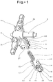
- FIG. 1 is a perspective assembly of the tilting member for switch, according to an embodiment of the invention seen from above.
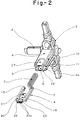
- Figure 2 is a representation similar to that which precedes, seen from below.
- Figure 3 is a side projection view of the entire rocker in action on a movable contact support.
- Figure 4 is a sectional view on line A-A of Figure 3.
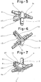
- Figures 5, 6 and 7 are perspective representations seen from above, from the side and from below of the tilting member or spider.
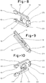
- Figures 8, 9 and 10 are perspective representations seen from the side, in shortcut and on the side opposite to the slide.
- Figures 11 and 12 are perspective side views of the slide in an alternative embodiment according to the invention.
- the number (1) generally indicates the tilting member, the (2) being the transverse pivot and articulation axis, (3-3a) being the two branches of the longitudinal arm tilting which has means (3b-3c) for fixing the key and, the core of which projects vertically the member (5) housing for the sliding mechanisms.
- This member (5) is composed of two substantially rectangular walls (4-4a) prismatic and separated by a housing (6) for the sliding mechanisms which are, internally, arranged to guide the spring (7) for tensioning the sliding by means of half canals in half rod (8-9) cut inside these (10-11).
- the housing (6) in the lateral openings has small partitions (12-13) (fig. 4 and 6) central and slightly set back from the outer edge of the walls (4-4a) of the vertical member (5) which serve of engagement or fixing for the anchoring means of the slide.
- the sliding part (14) is a U-shaped fork which, in the free ends of its parallel branches (17-18) includes anchoring hooks (15-16) arranged for its engagement against the upper edge of the small partitions (12-13) which partially close the opening (6) between the walls (4-4a) of the vertical member (5).
- anchoring hooks (15-16) are oriented towards the inside of the vertical branches (17-18) of the "U" fork ( 14) so that the engagement is made from the outside inside the small partitions (12-13) and whose removal prevents the most important part of the branches (17-18) beyond the edges of the vertical member (5).
- the anchoring hooks (15a-16a) of the version of FIGS. 11 and 12 are oriented towards the outside of the branches (17-18), the engagement occurring on the small partitions (12-13) of the inside outside. In this case, the fork opening (14) must be tightened to be mounted inside the housing (6) of the vertical member (5).
- the tension spring (7) is embedded in a rod (21), coaxial with a cylindrical billet (19) which vertically cuts the lower common section (20) of the fork (14).
- This rod has an oblong section with lateral facets (22) which increase the transverse diameter of the rod (21) so that the spring (7) is clamped by pressure.
- its position in the slide (14) is ensured, while also being guided, when it is inserted into the housing (6) of the vertical member (5), by the half channels of half-cut rod (8-9) in the interior faces of the walls (10-11).
- This arrangement ensures that the spring does not come out of the housing (6) when it undergoes during the various maneuvers the contractile tensions of the effort and the logical deformations of the latter.
- the slide (14) is provided with an exceptional slide point (23) which is aligned with the lower edge of the common side (20) of the fork (14), with a width equivalent to the diameter of the billet (19).
- This point (23) has a semi-round friction edge (24) which ensures good sliding on the surface of the base (25) on which it rubs uniformly over its entire width.
- the rounded tip (24) can be formed of longitudinal grooves (24a) (fig. 2) which ensure the permanent friction of one of its edges, whatever the inclination of the slide ( 14) in its respective maneuvers.
- the tip (23) of the slide (14) rubs on its edge (24-24a) uniformly and over the entire width of the base (25) of the movable contact support (fig. 3) by moving the pendulum in its back and forth movements to carry the tabs (26-26a) and their respective contacts (26b-26c) against the fixed terminals.
Abstract
Description
L'invention concerne, selon le titre, un organe ou dispositif basculant spécialement développé comme interrupteur, poussoir ou commutateur de type à glisser pour manoeuvrer un support de contact mobile, balancier, développé pour n'importe quel système de mécanismes, mais particulièrement conçu pour les mécanismes modulaires du système compris dans le Brevet ES 545.782 d'EUNA, puisque ses caractéristiques structurelles, ses mesures adaptées au système et ses particularités fonctionnelles le rendent particulièrement pratique pour cette application.The invention relates, according to the title, to a tilting member or device specially developed as a slide-type switch, pusher or switch for operating a mobile contact support, pendulum, developed for any system of mechanisms, but particularly designed for the modular mechanisms of the system included in EUNA Patent ES 545,782, since its structural characteristics, its measures adapted to the system and its functional features make it particularly practical for this application.
C'est l'intention particulière de l'inventeur de doter le mécanisme d'avantages structuraux et fonctionnels par rapport aux mécanismes connus, en faisant ressortir la prétention de chercher les solutions pour assurer, d'un côté, un minimum de pièces et, d'un autre, que celles-ci soient montées d'une manière uniforme et linéaire entre elles et d'autre part que la glissade ou moyens opérationnels du support de contact agissent sur une large bande et uniformément sur ce support de contact, en alternant les versions pour le rendre plus efficace, aussi bien dans cette mission que dans la manière d'assembler ou de monter ses différentes parties.It is the particular intention of the inventor to provide the mechanism with structural and functional advantages over known mechanisms, by highlighting the claim to seek solutions to ensure, on the one hand, a minimum of parts and, on the other hand, that these are mounted in a uniform and linear manner between them and on the other hand that the slip or operational means of the contact support act on a wide strip and uniformly on this contact support, alternating versions to make it more efficient, both in this mission and in the way of assembling or mounting its different parts.
L'une des situations qui se posent fréquemment au cours de la fabrication est la manière de simplification standardisée du montage des pièces, qui a besoin de plusieurs opérations qui retardent, gênent ou renchérissent le coût du produit. Ceci du point de vue de la production.One of the situations which frequently arise in the course of manufacture is the way of standardized simplification of the assembly of the parts, which requires several operations which delay, hinder or increase the cost of the product. This from the point of view of production.
Du point de vue fonctionnel, il y a plusieurs exigences. La sécurité dans le logement du ressort de tension dans ses manoeuvres respectives; assurer son indéformabilité contre la tension en maintenant une bonne réponse au déplacement de la glissade lors de chaque manoeuvre: maintenir l'alignement et l'uniformité de friction de la pointe de glissade sur le support de contact mobile; contrôler et élargir le déplacement maximum des pattes de ce support de contact mobile et obtenir un coefficient optimum de rupture au débranchement.From a functional point of view, there are several requirements. Safety in the spring housing tension in their respective maneuvers; ensuring its non-deformability against tension by maintaining a good response to the displacement of the slide during each maneuver: maintaining the alignment and the uniformity of friction of the tip of slide on the movable contact support; control and widen the maximum displacement of the legs of this movable contact support and obtain an optimum breaking coefficient on disconnection.
Multiples et divers sont les systèmes basculants à glisser qui ont une structure composée d'un organe basculant, un organe à glisser et un ressort à tension qui peut agir de diverses manières.Multiple and diverse are the tilting sliding systems which have a structure composed of a tilting member, a sliding member and a tension spring which can act in various ways.
Parmi eux, le système le plus utilisé actuellement est une pointe de glissade, normalement une pointe émoussée contractile qui agit sur un support de contact mobile, à balancier, en forme de "V" (vé) et dont les extrémités portent les plots de contact.Among them, the most used system currently is a sliding point, normally a blunt contractile point which acts on a movable contact support, pendulum, in the shape of a "V" (vé) and whose ends carry the contact pads .
Les formes structurelles pour le logement du mécanisme sont du plus variable mais, des antécédents repérés lors des recherches sur les produits de ce genre dans l'art antérieur, SIMON, GUERIN, etc., aucun ne comporte les caractéristiques que l'on prétend pour l'objet de ce Brevet, selon les règles fondamentales signalées dans les paragraphes préliminaires.The structural forms for the housing of the mechanism are most variable but, antecedents identified during research on products of this kind in the prior art, SIMON, GUERIN, etc., none have the characteristics that are claimed for the subject of this Patent, according to the fundamental rules indicated in the preliminary paragraphs.
Le Brevet ES 545.782 EUNEA auquel se réfère principalement l'objet de ce Brevet, apportait un système de poussoir basculant qui opérait sur un support de contact mobile plat à balancier mais avec les conditions de n'importe lesquels des systèmes mentionnés dans les antécédents de l'art antérieur.Patent ES 545.782 EUNEA to which the object of this Patent mainly refers, provided a tilting push-button system which operated on a flat, pendulum contact contact support but with the conditions of any of the systems mentioned in the background of the prior art.
La prétention de l'invention est d'harmoniser une touche-basculante d'interrupteur pour petits mécanismes électriques, qui devienne commune aux différents modèles qui, en intégrant un système de ce type, sont actuellement commercialisés et, notamment, une touche-basculante pour le module porte-mécanismes du Brevet ES 545.782 d'EUNEA.The claim of the invention is to harmonize a rocker switch for small electrical mechanisms, which becomes common to the various models which, by incorporating a system of this type, are currently marketed and, in particular, a rocker switch for the mechanism holder module of EUNEA Patent ES 545.782.
Une idée essentielle de l'invention est que les mécanismes de la glissade puissent être montés successivement et simplement sur la partie inférieure ou dans une même position dans un membre aménagé de l'organe basculant.An essential idea of the invention is that the sliding mechanisms can be mounted successively and simply on the lower part or in the same position in a member provided with the tilting member.
Une idée également de l'invention est que le membre de logement reçoive la glissade et le ressort, moyen élastique contractile, de manière qu'il ne puisse sortir de son logement en supportant parfaitement les tensions et les courbes de déformation dans ses fonctions basculantes.An idea also of the invention is that the housing member receives the slip and the spring, contractile elastic means, so that it cannot leave its housing while perfectly supporting the tensions and the deformation curves in its tilting functions.
Une idée également de l'invention est que la glissade s'accroche au membre de logement du balancier, aussi bien à l'intérieur qu'à l'extérieur de celui-ci, par simple effet de pression élastique et de manière que la glissade ne dépasse pas ou ne surpasse pas sur la section du membre de logement.An idea also of the invention is that the slide clings to the housing member of the balance, both inside and outside thereof, by simple elastic pressure effect and so that the slide does not exceed or exceed the section of the accommodation member.
Une idée de l'invention est que les moyens de logement du ressort dans le membre et les moyens de fixation de celui-ci dans la glissade soient combinés pour assurer son reguidage coaxial au sein du premier et son blocage ou fixation avec le second.An idea of the invention is that the means for housing the spring in the member and the means for fixing the latter in the slide are combined to ensure its coaxial reguidation within the first and its blocking or fixing with the second.
Une idée essentielle également de l'invention est que la glissade comporte une pointe de friction sur le support de contact mobile qui agit uniformément sur la largeur complète de la surface de celui-ci, en rendant continu, uniforme et invariable son déplacement de va-et-vient.An essential idea also of the invention is that the slide comprises a point of friction on the mobile contact support which acts uniformly over the full width of the surface thereof, making continuous, uniform and invariable its movement of va- back and forth.
Une idée avantageuse également de l'invention est de pourvoir ou de donner au membre vertical des logements ou moyens extérieurs pour assurer le déplacement maximum du support de contact mobile, en assurant à la fois le débranchement de ceux-ci même si ils auraient pu communiquer (collés) par réchauffage des plots.An advantageous idea also of the invention is to provide or give the vertical member of the housing or external means to ensure the maximum displacement of the mobile contact support, by ensuring both the disconnection of these even if they could have communicated (glued) by heating the studs.
Par rapport à l'exposition précédente concernant l'activité inventive, celle-ci, structurellement se manifeste par une réalisation préférentielle de l'invention qui, à cet effet, est exposée en détail dans ce chapitre descriptif.Compared to the previous exposure concerning the inventive step, this one, structurally manifests itself by a preferential realization of the invention which, for this purpose, is exposed in detail in this descriptive chapter.
La structure principale du basculant comporte deux éléments communs, tels que l'axe transversal commun de pivotement pour basculement, le bras basculant longitudinal en croisillon sur cet axe, composé de deux parties égales pourvues des prises pour la touche, et du membre vertical intégrant, composant ou support de la glissade.The main structure of the rocker has two common elements, such as the common transverse pivot axis for rocking, the longitudinal rocking arm in a cross on this axis, composed of two equal parts provided with sockets for the key, and the integrated vertical member, component or support of the slide.
Une caractéristique principale du membre vertical, selon l'invention, est qu'il est intégré de deux parois prismatiques parallèles qui conforment à elles deux le logement des mécanismes de la glissade, pourvues intérieurement de canaux taillés dans leurs parois pour le guidage du ressort de tension et latéralement, sur les côtés ouverts, pourvue de petites cloisons centrales partielles qui constituent les points d'enclenchement pour la fixation de la glissade.A main characteristic of the vertical member, according to the invention, is that it is integrated with two parallel prismatic walls which together conform the housing of the sliding mechanisms, provided internally with channels cut in their walls for guiding the spring of tension and laterally, on the open sides, provided with small central partitions partial which constitute the points of engagement for the fixation of the slide.
Un autre détail lié aux petites cloisons de fixation de la glissade consiste en ce que, de préférence, elles se trouvent légèrement en retrait par rapport aux bords des parois du membre vertical pour maintenir un espace extérieur qui servira d'ajustement pour la glissade, dans une éventuelle version de fixation de celle-ci à l'extérieur.Another detail related to the small partitions for fixing the slide is that, preferably, they are slightly set back from the edges of the walls of the vertical member to maintain an external space which will serve as an adjustment for the slide, in a possible fixing version of this outside.
La glissade, organe principal du mécanisme, intègre essentiellement, selon l'invention, une pièce ayant la forme d'une fourche en "U", de section prismatique adéquate, qui dans les extrémités libres de ses branches parallèles a des moyens, vers l'intérieur ou vers l'extérieur, d'ancrage pour se fixer par enclenchement (et une certaine pression élastique) contre le bord supérieur des petites cloisons latérales. Ces moyens d'enclenchement sont des onglettes angulaires qui s'accrochent sur ces petites cloisons par effet de la pression dérivée du matériel de la fourche et du coefficient assuré par son ouverture centrale.The slide, the main organ of the mechanism, essentially incorporates, according to the invention, a part having the shape of a "U" fork, of adequate prismatic section, which in the free ends of its parallel branches has means, towards the 'inside or outside, anchor to fix by snap (and a certain elastic pressure) against the upper edge of the small side partitions. These engagement means are angular tabs which hang on these small partitions by the effect of the pressure derived from the material of the fork and the coefficient provided by its central opening.
La glissade, sur son côté commun, selon l'invention, comprend une billette prismatique axiale qui présente à l'intérieur une tige coaxiale à celle-ci et une section oblongue qui a des facettes plates latérales pour recevoir et loger à pression l'extrémité inférieure du ressort, en produisant une déformation relative de celui-ci, mais en assurant son immobilisation. Action qui, associée à son reguidage à travers les tailles intérieures du membre vertical, absorbent les tensions du ressort dans ses réactions contractiles en empêchant que le ressort soit délogé rendant le mécanisme inefficace.The slide, on its common side, according to the invention, comprises an axial prismatic billet which has on the inside a rod coaxial therewith and an oblong section which has lateral flat facets for receiving and accommodating the pressure end lower spring, producing a relative deformation thereof, but ensuring its immobilization. Action which, associated with its reguidation through the internal sizes of the vertical member, absorb the tensions of the spring in its contractile reactions by preventing the spring from being dislodged making the mechanism ineffective.
Une autre particularité avantageuse de la glissade consiste en ce que de l'extérieur, la billette est associée à une pointe de glissade qui est en alignée avec le bras commun de la fourche, qui a une dimension équivalente au diamètre de la billette et une pointe de friction émoussée ou demi arrondie qui est disposée transversalement à la base du support de contact mobile, en glissant uniformément sur cette base et en la cernant de part et d'autre, de sorte que le déplacement du support de contact se fait sur toute l'étendue de sa base, en assurant son déplacement et en évitant tout déséquilibre ou altération, balancement, déplacement ou dénivellement du tout petit support de contact mobile.Another advantageous feature of sliding is that from the outside, the billet is associated with a sliding point which is aligned with the common arm of the fork, which has a dimension equivalent to the diameter of the billet and a point of blunt or semi-rounded friction which is arranged transversely to the base of the movable contact support, sliding uniformly on this base and surrounding it on both sides, so that the displacement of the contact support takes place over all 'extent of its base, ensuring its displacement and avoiding any imbalance or alteration, swaying, displacement or unevenness of any small mobile contact support.
En rapport avec le comportement de ce déplacement et afin d'assurer un bon contact ou le débranchement de ce lui-ci, le membre vertical du basculant, selon l'invention, de l'extérieur, comprend les rabaissements ou dépressions respectifs localisés dans ses extrémités inférieures, en assurant un déplacement maximum du support de contact mobile lorsque la patte de celui-ci est rentrée, tangentiellement, dans la paroi du membre vertical. Cette approximation maximum assure que la patte opposée se plaque de manière efficace contre la borne (contact) fixe. Elle assure également de manière efficace que dans le déplacement contraire, la glissade entraîne fortement la patte tangente, en assurant la rupture même si le contact restait communiqué pour une cause éventuelle quelconque, généralement un réchauffage ou un court-circuit.In relation to the behavior of this movement and in order to ensure good contact or disconnection thereof, the vertical member of the rocker, according to the invention, from the outside, comprises the respective lowerings or depressions located in its lower ends, ensuring maximum displacement of the movable contact support when the lug of the latter is retracted, tangentially, into the wall of the vertical member. This maximum approximation ensures that the opposite tab is effectively pressed against the fixed terminal (contact). It also effectively ensures that in the opposite movement, the slide strongly drives the tangent tab, ensuring rupture even if the contact remains communicated for any possible cause, generally a reheating or a short circuit.
La friction linéale assurée par la pointe large de la glissade, avec une bande de friction qui correspond au point maximum de l'arc du bord émoussé de cette pointe, et où ce bord peut être réalisé avec un profil longitudinalement strié pour que toute déviation de l'angle d'appui de la glissade sur le support de contact mobile permette d'assurer l'appui de l'une de ces stries et la friction sûre de la pointe de la glissade.The linear friction ensured by the broad point of the slide, with a friction band which corresponds to the maximum point of the arc of the blunt edge of this point, and where this edge can be produced with a longitudinally striated profile so that any deviation from the angle of support of the slide on the mobile contact support makes it possible to ensure the support of one of these ridges and the safe friction of the tip of the slide.
Nous réalisons ci-dessous une idée plus ample des caractéristiques essentielles de l'invention en faisant référence à la planche de dessin jointe à ce mémoire, dans laquelle sont représentés, de manière quelque peu schématique et à titre d'exemple uniquement, les détails préférés de l'invention.We realize below a broader idea of the essential characteristics of the invention by referring to the drawing board attached to this memoir, in which are represented, somewhat schematically and by way of example only, the preferred details of the invention.
La figure 1 est un ensemble en perspective de l'organe basculant pour interrupteur, selon une réalisation de l'invention vue du dessus.Figure 1 is a perspective assembly of the tilting member for switch, according to an embodiment of the invention seen from above.
La figure 2 est une représentation pareille à celle qui précède, vue du dessous.Figure 2 is a representation similar to that which precedes, seen from below.
La figure 3 est une vue en projection latérale de l'ensemble du basculant en action sur un support de contact mobile.Figure 3 is a side projection view of the entire rocker in action on a movable contact support.
La figure 4 est une vue en section sur la ligne A-A de la figure 3.Figure 4 is a sectional view on line A-A of Figure 3.
Les figures 5, 6 et 7 sont des représentations en perspective vues du dessus, de côté et du dessous de l'organe basculant ou croisillon.Figures 5, 6 and 7 are perspective representations seen from above, from the side and from below of the tilting member or spider.
Les figures 8, 9 et 10 sont des représentations en perspective vues de côté, en raccourci et du côté opposé à la glissade.Figures 8, 9 and 10 are perspective representations seen from the side, in shortcut and on the side opposite to the slide.
Les figures 11 et 12 sont des vues en perspective de côté de la glissade dans une variante de réalisation selon l'invention.Figures 11 and 12 are perspective side views of the slide in an alternative embodiment according to the invention.
Par rapport à ces illustrations, le numéro (1) signale d'une manière générale l'organe basculant, le (2) étant l'axe transversal de pivotement et d'articulation, (3-3a) étant les deux branches du bras longitudinal basculant qui a des moyens (3b-3c) pour la fixation de la touche et, du noyau duquel se projette verticalement le membre (5) de logement pour les mécanismes de la glissade.Compared to these illustrations, the number (1) generally indicates the tilting member, the (2) being the transverse pivot and articulation axis, (3-3a) being the two branches of the longitudinal arm tilting which has means (3b-3c) for fixing the key and, the core of which projects vertically the member (5) housing for the sliding mechanisms.
Ce membre (5) est composé de deux parois sensiblement rectangulaires (4-4a) prismatiques et séparées para un logement (6) pour les mécanismes de la glissade qui sont, intérieurement, aménagés pour guider le ressort (7) de tension de la glissade au moyen de demi canaux en demi tige (8-9) taillés à l'intérieur de celles-ci (10-11).This member (5) is composed of two substantially rectangular walls (4-4a) prismatic and separated by a housing (6) for the sliding mechanisms which are, internally, arranged to guide the spring (7) for tensioning the sliding by means of half canals in half rod (8-9) cut inside these (10-11).
Le logement (6) dans les ouvertures latérales présente de petites cloisons (12-13) (fig. 4 et 6) centrales et légèrement en retrait par rapport au bord extérieur des parois (4-4a) du membre vertical (5) qui servent d'enclenchement ou de fixation pour les moyens d'ancrage de la glissade.The housing (6) in the lateral openings has small partitions (12-13) (fig. 4 and 6) central and slightly set back from the outer edge of the walls (4-4a) of the vertical member (5) which serve of engagement or fixing for the anchoring means of the slide.
La pièce de glissade (14) est une fourche en "U" qui, dans les extrémités libres de ses branches parallèles (17-18) comprend des crochets d'ancrage (15-16) disposées pour son enclenchement contre le bord supérieur des petites cloisons (12-13) qui ferment partiellement l'ouverture (6) entre les parois (4-4a) du membre vertical (5).The sliding part (14) is a U-shaped fork which, in the free ends of its parallel branches (17-18) includes anchoring hooks (15-16) arranged for its engagement against the upper edge of the small partitions (12-13) which partially close the opening (6) between the walls (4-4a) of the vertical member (5).
Ces crochets d'ancrage (15-16), selon la version des figures 1, 2, 4, 8, 9 et 10, sont orientés vers l'intérieur des branches verticales (17-18) de la fourche en "U" (14) de sorte que l'enclenchement est fait de l'extérieur à l'intérieur des petites cloisons (12-13) et dont le retrait évite que la partie la plus importante des branches (17-18) dépasse les bords du membre vertical (5). Mais les crochets d'ancrage (15a-16a) de la version des figures 11 et 12 sont orientés vers l'extérieur des branches (17-18), l'enclenchement se produisant sur les petites cloisons (12-13) de l'intérieur à l'extérieur. Dans ce cas, l'ouverture de la fourche (14) doit être resserrée pour être montée à l'intérieur du logement (6) du membre vertical (5).These anchoring hooks (15-16), according to the version of FIGS. 1, 2, 4, 8, 9 and 10, are oriented towards the inside of the vertical branches (17-18) of the "U" fork ( 14) so that the engagement is made from the outside inside the small partitions (12-13) and whose removal prevents the most important part of the branches (17-18) beyond the edges of the vertical member (5). But the anchoring hooks (15a-16a) of the version of FIGS. 11 and 12 are oriented towards the outside of the branches (17-18), the engagement occurring on the small partitions (12-13) of the inside outside. In this case, the fork opening (14) must be tightened to be mounted inside the housing (6) of the vertical member (5).
L'opération simplifiée de montage est facilitée par le fait que les mécanismes sont logés par l'entrée inférieure du logement (6) du membre vertical (5) conjointement. Il suffit que le ressort (7) soit monté sur les moyens dont est pourvu à cet effet la glissade (14) et se loge de manière unitaire jusqu'à ce que les crochets d'ancrage (15-16) ou (15a-16a) soient enclenchés dans les parois (12-13).The simplified mounting operation is facilitated by the fact that the mechanisms are housed by the lower inlet of the housing (6) of the vertical member (5) jointly. It suffices that the spring (7) is mounted on the means which is provided for this purpose the slide (14) and is housed in a unitary manner until the anchoring hooks (15-16) or (15a-16a ) are engaged in the walls (12-13).
Le ressort de tension (7) est encastré dans une tige (21), coaxiale à une billette cylindrique (19) qui coupe verticalement le tronçon commun inférieur (20) de la fourche (14). Cette tige a une section oblongue à facettes latérales (22) qui augmentent le diamètre transversal de la tige (21) pour que le ressort (7) s'encastre par pression. De cette manière, sa position dans la glissade (14) est assurée, en se guidant également, lors de son introduction dans le logement (6) du membre vertical (5), par les demi canaux de demi tige (8-9) taillés dans les faces intérieures des parois (10-11). Cette disposition assure que le ressort ne sorte pas du logement (6) lorsqu'il subit au cours des différentes manoeuvres les tensions contractiles de l'effort et les déformations logiques de celui-ci.The tension spring (7) is embedded in a rod (21), coaxial with a cylindrical billet (19) which vertically cuts the lower common section (20) of the fork (14). This rod has an oblong section with lateral facets (22) which increase the transverse diameter of the rod (21) so that the spring (7) is clamped by pressure. In this way, its position in the slide (14) is ensured, while also being guided, when it is inserted into the housing (6) of the vertical member (5), by the half channels of half-cut rod (8-9) in the interior faces of the walls (10-11). This arrangement ensures that the spring does not come out of the housing (6) when it undergoes during the various maneuvers the contractile tensions of the effort and the logical deformations of the latter.
La glissade (14) est dotée d'une pointe de glissade (23) exceptionnelle qui est alignée avec le bord inférieur du côté commun (20) de la fourche (14), avec une largeur équivalente au diamètre de la billette (19). Une dimension qui couvre la largeur totale de la base (25) du support de contact mobile (fig. 3). Cette pointe (23) a un bord de friction (24) demi rond qui assure une bonne glissade sur la surface de la base (25) sur laquelle elle se frotte de manière uniforme sur toute sa largeur. Néanmoins, dans une version optionnelle, la pointe arrondie (24) peut être formée de stries longitudinales (24a)(fig. 2) qui assurent la friction permanente de l'un de ses bords, quelle que soit l'inclinaison de la glissade (14) dans ses manoeuvres respectives.The slide (14) is provided with an exceptional slide point (23) which is aligned with the lower edge of the common side (20) of the fork (14), with a width equivalent to the diameter of the billet (19). A dimension which covers the total width of the base (25) of the movable contact support (fig. 3). This point (23) has a semi-round friction edge (24) which ensures good sliding on the surface of the base (25) on which it rubs uniformly over its entire width. However, in an optional version, the rounded tip (24) can be formed of longitudinal grooves (24a) (fig. 2) which ensure the permanent friction of one of its edges, whatever the inclination of the slide ( 14) in its respective maneuvers.
Comme il a été dit, la pointe (23) de la glissade (14) frotte sur son bord (24-24a) de manière uniforme et sur toute la largeur de la base (25) du support de contact mobile (fig. 3) en déplaçant le balancier dans ses mouvements de va-et-vient pour porter les pattes (26-26a) et leurs contacts respectifs (26b-26c) contre les bornes fixes. Ce déplacement, dû aux caractéristiques de la pointe (23), est assuré de manière optimale, mais on a prévu de plus les rabaissements (27-28) correspondants extérieurs sur les extrémités inférieures des parois (4-4a) pour permettre que la patte (26 ou 26a) du support de contact mobile opposée à la patte déplacée, tangente au membre vertical (5), se loge dans le rabaissement (27-28) respectif, en assurant le déplacement maximum de la patte opposée et en garantissant ainsi le contact avec les bornes fixes.As has been said, the tip (23) of the slide (14) rubs on its edge (24-24a) uniformly and over the entire width of the base (25) of the movable contact support (fig. 3) by moving the pendulum in its back and forth movements to carry the tabs (26-26a) and their respective contacts (26b-26c) against the fixed terminals. This displacement, due to the characteristics of the tip (23), is ensured in an optimal manner, but provision has been made in addition for the corresponding lowerings (27-28) on the lower ends of the walls (4-4a) to allow the tab (26 or 26a) of the movable contact support opposite the displaced tab, tangent to the vertical member (5), is housed in the respective lowering (27-28), ensuring the maximum displacement of the opposite tab and thus guaranteeing the contact with fixed terminals.
La proximité ou le rapprochement de la patte tangente (26 ou 26a) dans le rabaissement (27-28) opposé à celle du contact permet que le déplacement de retour se réalise de manière efficace, car le membre vertical (5) tirera fortement sur la patte tangente en provoquant la séparation (rupture) certaine de la patte en contact, en l'obligeant à se séparer même si elle est restée communiquée ou court-circuitée.The proximity or approximation of the tangent tab (26 or 26a) in the lowering (27-28) opposite to that of the contact allows the return movement to be carried out effectively, because the vertical member (5) will strongly pull on the tangent leg causing certain separation (rupture) of the leg in contact, forcing it to separate even if it has remained communicated or short-circuited.
Une fois la nature de l'invention convenablement décrite, on signale, pour servir et valoir ce que de droit, que celle-ci ne se limite pas aux détails exacts de cette exposition mais, qu'au contraire, on y introduira les modifications considérées opportunes, à condition de ne pas altérer ses caractéristiques essentielles, qui sont revendiquées ci-après.Once the nature of the invention has been properly described, it is pointed out, in order to serve and assert what is right, that it is not limited to the exact details of this exhibition but, on the contrary, we will introduce the modifications considered timely, provided that it does not alter its essential characteristics, which are claimed below.
Claims (8)
Priority Applications (5)
| Application Number | Priority Date | Filing Date | Title |
|---|---|---|---|
| ES94500209T ES2144499T3 (en) | 1994-12-29 | 1994-12-29 | SLIP TILTING ORGAN FOR ELECTRICAL SWITCHES OR MECHANISMS. |
| EP94500209A EP0720191B1 (en) | 1994-12-29 | 1994-12-29 | Sliding rocker for electric switches or mechanisms |
| PT94500209T PT720191E (en) | 1994-12-29 | 1994-12-29 | ROLLING ORGAO FOR SLIDING FOR SWITCHES OR ELECTRICAL MECHANISMS |
| AT94500209T ATE191096T1 (en) | 1994-12-29 | 1994-12-29 | SLIDING ROCKER DEVICE FOR ELECTRICAL SWITCHES OR MECHANISMS |
| DE69423638T DE69423638D1 (en) | 1994-12-29 | 1994-12-29 | Sliding rocker for electrical switches or mechanisms |
Applications Claiming Priority (1)
| Application Number | Priority Date | Filing Date | Title |
|---|---|---|---|
| EP94500209A EP0720191B1 (en) | 1994-12-29 | 1994-12-29 | Sliding rocker for electric switches or mechanisms |
Publications (2)
| Publication Number | Publication Date |
|---|---|
| EP0720191A1 true EP0720191A1 (en) | 1996-07-03 |
| EP0720191B1 EP0720191B1 (en) | 2000-03-22 |
Family
ID=8218177
Family Applications (1)
| Application Number | Title | Priority Date | Filing Date |
|---|---|---|---|
| EP94500209A Expired - Lifetime EP0720191B1 (en) | 1994-12-29 | 1994-12-29 | Sliding rocker for electric switches or mechanisms |
Country Status (5)
| Country | Link |
|---|---|
| EP (1) | EP0720191B1 (en) |
| AT (1) | ATE191096T1 (en) |
| DE (1) | DE69423638D1 (en) |
| ES (1) | ES2144499T3 (en) |
| PT (1) | PT720191E (en) |
Cited By (1)
| Publication number | Priority date | Publication date | Assignee | Title |
|---|---|---|---|---|
| WO2003030196A2 (en) * | 2001-09-27 | 2003-04-10 | Vimar S.P.A. | A mechanism for compression actuating, by means of a rocking key, switches, change-over switches, selector switches and the like |
Citations (5)
| Publication number | Priority date | Publication date | Assignee | Title |
|---|---|---|---|---|
| FR1492835A (en) * | 1966-02-03 | 1967-08-25 | Electrical switch with remote central input terminal | |
| DE7322290U (en) * | 1973-06-15 | 1973-09-13 | Giersiepen G | Electric rocker or toggle switch |
| DE3620416A1 (en) * | 1985-07-31 | 1987-02-12 | Eunea Electrotecnica | MODULAR SYSTEM FOR THE PRODUCTION OF SMALL ELECTRICAL MATERIAL |
| US5045654A (en) * | 1989-12-14 | 1991-09-03 | Eaton Corporation | Switch assembly |
| DE4237724C1 (en) * | 1992-11-09 | 1993-12-09 | Kostal Leopold Gmbh & Co Kg | Electric switch with different switch functions - uses contact mat with selectively ruptured separation prints corresp. to different switch function contact ranges |
-
1994
- 1994-12-29 EP EP94500209A patent/EP0720191B1/en not_active Expired - Lifetime
- 1994-12-29 DE DE69423638T patent/DE69423638D1/en not_active Expired - Lifetime
- 1994-12-29 AT AT94500209T patent/ATE191096T1/en not_active IP Right Cessation
- 1994-12-29 PT PT94500209T patent/PT720191E/en unknown
- 1994-12-29 ES ES94500209T patent/ES2144499T3/en not_active Expired - Lifetime
Patent Citations (5)
| Publication number | Priority date | Publication date | Assignee | Title |
|---|---|---|---|---|
| FR1492835A (en) * | 1966-02-03 | 1967-08-25 | Electrical switch with remote central input terminal | |
| DE7322290U (en) * | 1973-06-15 | 1973-09-13 | Giersiepen G | Electric rocker or toggle switch |
| DE3620416A1 (en) * | 1985-07-31 | 1987-02-12 | Eunea Electrotecnica | MODULAR SYSTEM FOR THE PRODUCTION OF SMALL ELECTRICAL MATERIAL |
| US5045654A (en) * | 1989-12-14 | 1991-09-03 | Eaton Corporation | Switch assembly |
| DE4237724C1 (en) * | 1992-11-09 | 1993-12-09 | Kostal Leopold Gmbh & Co Kg | Electric switch with different switch functions - uses contact mat with selectively ruptured separation prints corresp. to different switch function contact ranges |
Cited By (4)
| Publication number | Priority date | Publication date | Assignee | Title |
|---|---|---|---|---|
| WO2003030196A2 (en) * | 2001-09-27 | 2003-04-10 | Vimar S.P.A. | A mechanism for compression actuating, by means of a rocking key, switches, change-over switches, selector switches and the like |
| WO2003030196A3 (en) * | 2001-09-27 | 2003-08-28 | Vimar Spa | A mechanism for compression actuating, by means of a rocking key, switches, change-over switches, selector switches and the like |
| MD3524C2 (en) * | 2001-09-27 | 2008-09-30 | Vimar S.P.A. | Mechanism of pressure action by means of a switchboard key for switches, commutators, selection commutators and other similar devices |
| HRP20040283B1 (en) * | 2001-09-27 | 2009-10-31 | Vimar S.P.A. | A mechanism for compression actuating, by means of a rocking key, switches, change-over switches, selector switches and the like |
Also Published As
| Publication number | Publication date |
|---|---|
| EP0720191B1 (en) | 2000-03-22 |
| ES2144499T3 (en) | 2000-06-16 |
| DE69423638D1 (en) | 2000-04-27 |
| ATE191096T1 (en) | 2000-04-15 |
| PT720191E (en) | 2000-08-31 |
Similar Documents
| Publication | Publication Date | Title |
|---|---|---|
| EP0847710B1 (en) | Spring hinge for hair article | |
| FR2624806A1 (en) | AUTOMOTIVE VEHICLE MOUNTING MIRROR WITH REMOVABLE MOUNTING | |
| FR2590194A1 (en) | STAPLER MECHANISM | |
| EP0661938B1 (en) | Unfolding buckle-type clasp for a bracelet | |
| EP0205379B1 (en) | Buckle, in particular for safety belts | |
| CH643682A5 (en) | SLIDING CONTACT SWITCH. | |
| EP0576367B1 (en) | Mobile hook for a shedding mechanism | |
| EP0720191B1 (en) | Sliding rocker for electric switches or mechanisms | |
| EP0178974B1 (en) | Connecting devices for printed-circuit boards | |
| FR2460536A1 (en) | MULTIPLE SELECTIVE SWITCH, IN PARTICULAR FOR MOTOR VEHICLES | |
| BE1000823A3 (en) | Joint. | |
| FR2518192A1 (en) | Clamp for joining light alloy sections - is U=shaped clip with gripping hooks and tightening screw to engage sections | |
| EP0724052B1 (en) | Vehicle door handle with quick wedge-cam assembly | |
| FR2556847A1 (en) | SEMI-PERMANENT CONNECTION DEVICE FOR OPTICAL FIBERS AND METHOD FOR ITS IMPLEMENTATION | |
| EP1374716B1 (en) | Buckle for bracelet | |
| FR2704120A1 (en) | Folding clasp for bracelet. | |
| EP0159075A1 (en) | Video tape cassette | |
| FR2758963A1 (en) | COOKING GRID WITH ARTICULATED PANELS | |
| FR2583472A1 (en) | Method for mounting a caged nut on a panel or the like and caged nut for implementing this method | |
| FR2634043A1 (en) | Clip mainly for a display support frame | |
| FR2568650A1 (en) | Device for clamping a flexible element such as a cord, string, lace or the like | |
| EP0140754B1 (en) | Switch operated by a pivoting lever, particularly for automotive vehicles | |
| FR2766676A1 (en) | Hair grip with spring=loaded hinge | |
| EP0149944B1 (en) | Connection with swiveling u shaped clamp | |
| EP0406097B1 (en) | Switch, especially for automotive vehicles |
Legal Events
| Date | Code | Title | Description |
|---|---|---|---|
| PUAI | Public reference made under article 153(3) epc to a published international application that has entered the european phase |
Free format text: ORIGINAL CODE: 0009012 |
|
| AK | Designated contracting states |
Kind code of ref document: A1 Designated state(s): AT BE CH DE DK ES FR GB GR IE IT LI LU MC NL PT SE |
|
| RAP1 | Party data changed (applicant data changed or rights of an application transferred) |
Owner name: MATERIAL DE INSTALACION EUNEA, S.A. |
|
| 17P | Request for examination filed |
Effective date: 19961216 |
|
| RAP1 | Party data changed (applicant data changed or rights of an application transferred) |
Owner name: SCHNEIDER ELECTRIC ESPANA, S.A. |
|
| GRAG | Despatch of communication of intention to grant |
Free format text: ORIGINAL CODE: EPIDOS AGRA |
|
| 17Q | First examination report despatched |
Effective date: 19990407 |
|
| GRAG | Despatch of communication of intention to grant |
Free format text: ORIGINAL CODE: EPIDOS AGRA |
|
| GRAH | Despatch of communication of intention to grant a patent |
Free format text: ORIGINAL CODE: EPIDOS IGRA |
|
| GRAH | Despatch of communication of intention to grant a patent |
Free format text: ORIGINAL CODE: EPIDOS IGRA |
|
| GRAA | (expected) grant |
Free format text: ORIGINAL CODE: 0009210 |
|
| AK | Designated contracting states |
Kind code of ref document: B1 Designated state(s): AT BE CH DE DK ES FR GB GR IE IT LI LU MC NL PT SE |
|
| PG25 | Lapsed in a contracting state [announced via postgrant information from national office to epo] |
Ref country code: SE Free format text: THE PATENT HAS BEEN ANNULLED BY A DECISION OF A NATIONAL AUTHORITY Effective date: 20000322 Ref country code: NL Free format text: LAPSE BECAUSE OF FAILURE TO SUBMIT A TRANSLATION OF THE DESCRIPTION OR TO PAY THE FEE WITHIN THE PRESCRIBED TIME-LIMIT Effective date: 20000322 Ref country code: IT Free format text: LAPSE BECAUSE OF FAILURE TO SUBMIT A TRANSLATION OF THE DESCRIPTION OR TO PAY THE FEE WITHIN THE PRESCRIBED TIME-LIMIT;WARNING: LAPSES OF ITALIAN PATENTS WITH EFFECTIVE DATE BEFORE 2007 MAY HAVE OCCURRED AT ANY TIME BEFORE 2007. THE CORRECT EFFECTIVE DATE MAY BE DIFFERENT FROM THE ONE RECORDED. Effective date: 20000322 Ref country code: GR Free format text: LAPSE BECAUSE OF NON-PAYMENT OF DUE FEES Effective date: 20000322 Ref country code: GB Free format text: LAPSE BECAUSE OF FAILURE TO SUBMIT A TRANSLATION OF THE DESCRIPTION OR TO PAY THE FEE WITHIN THE PRESCRIBED TIME-LIMIT Effective date: 20000322 Ref country code: AT Free format text: LAPSE BECAUSE OF FAILURE TO SUBMIT A TRANSLATION OF THE DESCRIPTION OR TO PAY THE FEE WITHIN THE PRESCRIBED TIME-LIMIT Effective date: 20000322 |
|
| REF | Corresponds to: |
Ref document number: 191096 Country of ref document: AT Date of ref document: 20000415 Kind code of ref document: T |
|
| REG | Reference to a national code |
Ref country code: CH Ref legal event code: EP |
|
| REF | Corresponds to: |
Ref document number: 69423638 Country of ref document: DE Date of ref document: 20000427 |
|
| REG | Reference to a national code |
Ref country code: IE Ref legal event code: FG4D Free format text: FRENCH |
|
| REG | Reference to a national code |
Ref country code: ES Ref legal event code: FG2A Ref document number: 2144499 Country of ref document: ES Kind code of ref document: T3 |
|
| PG25 | Lapsed in a contracting state [announced via postgrant information from national office to epo] |
Ref country code: DK Free format text: LAPSE BECAUSE OF FAILURE TO SUBMIT A TRANSLATION OF THE DESCRIPTION OR TO PAY THE FEE WITHIN THE PRESCRIBED TIME-LIMIT Effective date: 20000622 |
|
| PG25 | Lapsed in a contracting state [announced via postgrant information from national office to epo] |
Ref country code: DE Free format text: LAPSE BECAUSE OF FAILURE TO SUBMIT A TRANSLATION OF THE DESCRIPTION OR TO PAY THE FEE WITHIN THE PRESCRIBED TIME-LIMIT Effective date: 20000624 |
|
| REG | Reference to a national code |
Ref country code: PT Ref legal event code: SC4A Free format text: AVAILABILITY OF NATIONAL TRANSLATION Effective date: 20000529 |
|
| NLV1 | Nl: lapsed or annulled due to failure to fulfill the requirements of art. 29p and 29m of the patents act | ||
| GBV | Gb: ep patent (uk) treated as always having been void in accordance with gb section 77(7)/1977 [no translation filed] |
Effective date: 20000322 |
|
| PG25 | Lapsed in a contracting state [announced via postgrant information from national office to epo] |
Ref country code: LU Free format text: LAPSE BECAUSE OF NON-PAYMENT OF DUE FEES Effective date: 20001229 Ref country code: IE Free format text: LAPSE BECAUSE OF NON-PAYMENT OF DUE FEES Effective date: 20001229 |
|
| PG25 | Lapsed in a contracting state [announced via postgrant information from national office to epo] |
Ref country code: MC Free format text: THE PATENT HAS BEEN ANNULLED BY A DECISION OF A NATIONAL AUTHORITY Effective date: 20001231 Ref country code: LI Free format text: LAPSE BECAUSE OF NON-PAYMENT OF DUE FEES Effective date: 20001231 Ref country code: CH Free format text: LAPSE BECAUSE OF NON-PAYMENT OF DUE FEES Effective date: 20001231 Ref country code: BE Free format text: LAPSE BECAUSE OF NON-PAYMENT OF DUE FEES Effective date: 20001231 |
|
| PLBE | No opposition filed within time limit |
Free format text: ORIGINAL CODE: 0009261 |
|
| STAA | Information on the status of an ep patent application or granted ep patent |
Free format text: STATUS: NO OPPOSITION FILED WITHIN TIME LIMIT |
|
| 26N | No opposition filed | ||
| BERE | Be: lapsed |
Owner name: S.A. SCHNEIDER ELECTRIC ESPANA Effective date: 20001231 |
|
| REG | Reference to a national code |
Ref country code: CH Ref legal event code: PL |
|
| REG | Reference to a national code |
Ref country code: IE Ref legal event code: MM4A |
|
| REG | Reference to a national code |
Ref country code: ES Ref legal event code: GC2A Effective date: 20090714 |
|
| PGFP | Annual fee paid to national office [announced via postgrant information from national office to epo] |
Ref country code: PT Payment date: 20111123 Year of fee payment: 18 Ref country code: ES Payment date: 20111201 Year of fee payment: 18 Ref country code: FR Payment date: 20111212 Year of fee payment: 18 |
|
| REG | Reference to a national code |
Ref country code: PT Ref legal event code: MM4A Free format text: LAPSE DUE TO NON-PAYMENT OF FEES Effective date: 20130701 |
|
| REG | Reference to a national code |
Ref country code: FR Ref legal event code: ST Effective date: 20130830 |
|
| PG25 | Lapsed in a contracting state [announced via postgrant information from national office to epo] |
Ref country code: PT Free format text: LAPSE BECAUSE OF NON-PAYMENT OF DUE FEES Effective date: 20130701 |
|
| PG25 | Lapsed in a contracting state [announced via postgrant information from national office to epo] |
Ref country code: FR Free format text: LAPSE BECAUSE OF NON-PAYMENT OF DUE FEES Effective date: 20130102 |
|
| REG | Reference to a national code |
Ref country code: ES Ref legal event code: FD2A Effective date: 20140306 |
|
| PG25 | Lapsed in a contracting state [announced via postgrant information from national office to epo] |
Ref country code: ES Free format text: LAPSE BECAUSE OF NON-PAYMENT OF DUE FEES Effective date: 20121230 |