EP0720156A2 - Obere Kopftrommelanordnung - Google Patents
Obere Kopftrommelanordnung Download PDFInfo
- Publication number
- EP0720156A2 EP0720156A2 EP95115958A EP95115958A EP0720156A2 EP 0720156 A2 EP0720156 A2 EP 0720156A2 EP 95115958 A EP95115958 A EP 95115958A EP 95115958 A EP95115958 A EP 95115958A EP 0720156 A2 EP0720156 A2 EP 0720156A2
- Authority
- EP
- European Patent Office
- Prior art keywords
- upper drum
- inner part
- head
- screws
- drum
- Prior art date
- Legal status (The legal status is an assumption and is not a legal conclusion. Google has not performed a legal analysis and makes no representation as to the accuracy of the status listed.)
- Ceased
Links
- 239000007767 bonding agent Substances 0.000 description 4
- 238000000034 method Methods 0.000 description 1
- 238000012986 modification Methods 0.000 description 1
- 230000004048 modification Effects 0.000 description 1
- 230000000087 stabilizing effect Effects 0.000 description 1
Images

Classifications
-
- G—PHYSICS
- G11—INFORMATION STORAGE
- G11B—INFORMATION STORAGE BASED ON RELATIVE MOVEMENT BETWEEN RECORD CARRIER AND TRANSDUCER
- G11B15/00—Driving, starting or stopping record carriers of filamentary or web form; Driving both such record carriers and heads; Guiding such record carriers or containers therefor; Control thereof; Control of operating function
- G11B15/60—Guiding record carrier
- G11B15/61—Guiding record carrier on drum, e.g. drum containing rotating heads
-
- G—PHYSICS
- G11—INFORMATION STORAGE
- G11B—INFORMATION STORAGE BASED ON RELATIVE MOVEMENT BETWEEN RECORD CARRIER AND TRANSDUCER
- G11B5/00—Recording by magnetisation or demagnetisation of a record carrier; Reproducing by magnetic means; Record carriers therefor
- G11B5/48—Disposition or mounting of heads or head supports relative to record carriers ; arrangements of heads, e.g. for scanning the record carrier to increase the relative speed
- G11B5/52—Disposition or mounting of heads or head supports relative to record carriers ; arrangements of heads, e.g. for scanning the record carrier to increase the relative speed with simultaneous movement of head and record carrier, e.g. rotation of head
- G11B5/53—Disposition or mounting of heads on rotating support
-
- G—PHYSICS
- G11—INFORMATION STORAGE
- G11B—INFORMATION STORAGE BASED ON RELATIVE MOVEMENT BETWEEN RECORD CARRIER AND TRANSDUCER
- G11B15/00—Driving, starting or stopping record carriers of filamentary or web form; Driving both such record carriers and heads; Guiding such record carriers or containers therefor; Control thereof; Control of operating function
- G11B15/60—Guiding record carrier
- G11B15/66—Threading; Loading; Automatic self-loading
- G11B15/665—Threading; Loading; Automatic self-loading by extracting loop of record carrier from container
- G11B15/6653—Threading; Loading; Automatic self-loading by extracting loop of record carrier from container to pull the record carrier against drum
Definitions
- the present invention relates to a head drum assembly for use in a video cassette recorder; and, more particularly, to an upper head drum assembly in which one or more heads are securely and precisely fastened to an upper drum therein.
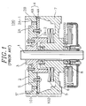
- a conventional head drum assembly 100 for use in a video cassette recorder comprises a rotating shaft 1 divided into an upper and a lower parts, an upper head drum assembly 101 and a lower head drum assembly 102.
- the upper head drum assembly 101 includes an upper drum 2 with an inner part 2A and an outer side surface 2B, the outer side surface 2B being provided with a pair of head windows (not shown) having a predetermined width, a flange 3, a pair of heads 4, each of the heads having a head chip 4B adjoined to a head base 4A, and a rotor transformer 5.
- the inner part 2A of the upper drum 2 is provided with a top and a bottom surfaces 2A-1, 2A-2.
- the lower head drum assembly 102 includes a stator transformer 6, a lower drum 7 and two sets of bearings 8.
- the upper drum 2 is joined with the upper part of the rotating shaft 1 via the flange 3; and the lower drum 7 is attached to the lower part of the rotating shaft 1 through the two sets of bearings 8.
- the rotor transformer 5 may be attached at bottom of the flange 3 using, e.g., a bonding agent.
- the stator transformer 6 for producing a predetermined electric signal may be fixed on the lower drum 7 using, e.g, a bonding agent, at a predetermined distance from the rotor transformer 5.
- the upper drum 2 is provided with a first and a second pairs of tapped holes, each of the tapped holes from the first pair extending upward from the bottom surface 2A-2 of the inner part 2A thereof and each of the tapped holes from the second pair extending downward from the top surface 2A-1 of the inner part 2A thereof. Furthermore, each of the first pair of tapped holes has a first screw (S); and, likewise, each of the second pair of tapped holes has a second screw(S').
- the heads 4 are secured to the bottom surface 2A-2 of the inner part 2A of the upper drum 2 by using the first screws (S) and the first pair of tapped holes in such a way that the head chips 4B from each of the heads 4 protrude past the outer side surface 2B of the upper drum 2 through the head windows.
- Vertical positions of the head chips 4B within the head drum assembly 100 are adjusted by using the second screws (S') in conjunction with the second pair of tapped holes.
- each of the heads 4 is first fixed to the bottom surface 2A-2 of the inner part 2A of the upper drum 2 by using the first screw (S) and one of the first pair of tapped holes. Thereafter, the upper and the lower drums 2, 7 are assembled; and then the vertical positions of the head chips 4B within the head drum assembly 100 are adjusted using the second screws (S') and one of the second pair of tapped holes.
- each of the tapped holes from the first and the second pairs, and hence the screws must be deep in length and wide in diameter.
- the current trend in designing the upper drum is to make the inner part of the upper drum as thin as possible for the purpose of reducing the production cost thereof.
- the inner part of the upper drum becomes too thin, however, tightening of the screws may cause a deformation of the inner part of the upper drum, making it difficult to securely fasten the heads to the bottom surface of the inner part of the upper drum and to precisely adjust the vertical positions of the head chips within the head drum assembly.
- an upper drum assembly for use in a video cassette recorder, comprising a rotating shaft, a flange, one or more heads, each of the heads having a head chip adjoined to a head base, an upper drum adjoined to the rotating shaft via the flange and provided with an inner part having a top and a bottom surfaces, the inner part having one or more openings, one or more through holes, and one or more recesses on the bottom surface thereof, one or more nut caps, each of the nut caps including a fixed part provided with a first tapped hole to be aligned with one of the through holes in the upper drum, a body part provided with a second tapped hole and an outer side surface, and a stepped part, one or more first screws, each of the first screws matching the first tapped hole in the fixed part on one of the nut caps and one of the through holes on the inner part of the upper drum, and one or more second screws, each of the second screws matching the second tapped hole in the body
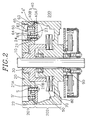
- FIG. 2 there is shown a cross sectional view of a head drum assembly 200 for use in a video cassette recorder incorporating therein an inventive upper head drum assembly 201.
- the head drum assembly 200 comprises a rotating shaft 10 divided into an upper and a lower parts, the inventive upper head drum assembly 201 and a lower head drum assembly 202.
- the upper head drum assembly 201 includes an upper drum 20 having an outer side surface 22 and a inner part 21 with a top and a bottom surfaces 21A, 21B, the outer side surface 22 being provided with one or more head windows (not shown) having a predetermined width, a flange 30, one or more heads 40, each of the heads having a head chip 40B joined to a head base 40A, a rotor transformer 50 and one or more nut caps 60, the nut caps 60 being used for attaching the heads 40 onto the bottom surface 21B of the inner part 21 of the upper drum 20.
- the lower head drum assembly 202 includes a stator transformer 70, a lower drum 80 and two sets of bearings 90.
- the upper drum 20 is joined with the upper part of the rotating shaft 10 via the flange 30 and the lower drum 80 is attached to the lower part of the rotating shaft 10 through the two sets of bearings 90.
- FIG. 3 a top view of half of the upper drum 20 in accordance with the present invention showing an exemplary opening 23 and a through hole 24, the through hole 24 extending upward from the bottom surface 21B to the top surface 21A of the inner part 21 thereof.
- an exemplary recess 21B' is provided on the bottom surface 21B of the inner part 21.
- the rotor transformer 50 may be attached at a bottom part of the flange 30 using, e.g., a bonding agent.
- the stator transformer 70 for producing a predetermined electric signal may be fixed inside the lower drum 80 using, e.g, a bonding agent, at a predetermined distance from the rotor transformer 50.
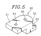
- Each of the nut caps 60 for attaching said each of the heads 40 is divided into a fixed part 61, a body part 62 with an outer side surface and a stepped part 63.
- the fixed part 61, the body part 62 and the stepped part 63 refer to a part of the nut cap 60 in contact with the top surface 21A of the inner part 21 of the upper drum 20, a part of the nut cap 60 fitted into the exemplary opening 23 in the upper drum 20 and a part of the nut cap 60 placed into the exemplary recess 21B', respectively.
- the fixed part 61 in each of the nut caps 60 is provided with a first tapped hole 64, the first tapped hole 64 passing through the fixed part 61.
- the body part 62 is provided with a second tapped hole 65, the second tapped hole 65 passing through the body part 62.
- the outer side surface of the body part 62 has a curvature matching the exemplary opening 23 so as to be easily inserted thereinto.
- the first and the second tapped holes 64, 65 are provided with a first and a second screws (S),(S'), respectively.
- One of the heads 40 is secured to the bottom surface 21B of the inner part 21 of the upper drum 20 by inserting and tightening the first screw (S) into one of the through holes 24 in the upper drum 20 and the first tapped hole 64 in the fixed part 61 on one of the nut caps 60 in such a way that the head chip 40B from the head 40 protrudes past the outer side surface 22 of the upper drum 20 through one of the head windows. Then, the vertical position of the head chip 40B within the head drum assembly 200 is adjusted by adjusting the second screw (S') inserted into the second tapped hole 65 on the corresponding nut cap 60.
- each of the heads is securely fastened to the bottom surface of the inner part of the upper drum by inserting the first screw into the first tapped hole in the fixed part of the nut cap and the through hole in the upper drum and the vertical position of the head chip is adjusted by adjusting the second screw inserted into the second tapped hole on the corresponding nut cap, there is a lesser degree of force acting on the inner part of the upper drum, minimizing the chance of deformation of the inner part and stabilizing the head chips to maintain their vertical positions within the head drum assembly.
Landscapes
- Adjustment Of The Magnetic Head Position Track Following On Tapes (AREA)
- Recording Or Reproducing By Magnetic Means (AREA)
Applications Claiming Priority (2)
| Application Number | Priority Date | Filing Date | Title |
|---|---|---|---|
| KR2019940036238U KR200153814Y1 (ko) | 1994-12-27 | 1994-12-27 | 헤드드럼 조립체의 헤드 조립구조 |
| KR9436238 | 1994-12-27 |
Publications (2)
| Publication Number | Publication Date |
|---|---|
| EP0720156A2 true EP0720156A2 (de) | 1996-07-03 |
| EP0720156A3 EP0720156A3 (de) | 1997-11-19 |
Family
ID=19403101
Family Applications (1)
| Application Number | Title | Priority Date | Filing Date |
|---|---|---|---|
| EP95115958A Ceased EP0720156A3 (de) | 1994-12-27 | 1995-10-10 | Obere Kopftrommelanordnung |
Country Status (5)
| Country | Link |
|---|---|
| US (1) | US5581426A (de) |
| EP (1) | EP0720156A3 (de) |
| JP (1) | JP2866331B2 (de) |
| KR (1) | KR200153814Y1 (de) |
| CN (1) | CN1139274A (de) |
Cited By (2)
| Publication number | Priority date | Publication date | Assignee | Title |
|---|---|---|---|---|
| GB2320796A (en) * | 1996-12-30 | 1998-07-01 | Daewoo Electronics Co Ltd | A head base assembly for a VCR for maintaining a video head chip in a horizontal state |
| EP1220206A1 (de) * | 2000-12-27 | 2002-07-03 | Thomson Licensing S.A. | Kopftrommelanordnung mit magnetischer Befestigung des rotierendes Übertragers |
Families Citing this family (3)
| Publication number | Priority date | Publication date | Assignee | Title |
|---|---|---|---|---|
| KR19980017840A (ko) * | 1996-08-31 | 1998-06-05 | 배순훈 | 헤드드럼 조립체의 헤드베이스 고정구조 |
| KR20060000015A (ko) * | 2004-06-28 | 2006-01-06 | 삼성전자주식회사 | 자기 기록/재생장치의 헤드드럼 조립체 조립방법 |
| KR20060012719A (ko) * | 2004-08-04 | 2006-02-09 | 삼성전자주식회사 | 회전드럼을 구비한 헤드드럼조립체 및 회전드럼 가공방법 |
Family Cites Families (11)
| Publication number | Priority date | Publication date | Assignee | Title |
|---|---|---|---|---|
| JPS603919U (ja) * | 1983-06-17 | 1985-01-12 | パイオニア株式会社 | ヘツドドラム装置 |
| JPH0110746Y2 (de) * | 1984-09-05 | 1989-03-28 | ||
| JPS6226613U (de) * | 1985-07-29 | 1987-02-18 | ||
| AT388823B (de) * | 1986-12-10 | 1989-09-11 | Philips Nv | Verfahren zum justieren der spalte von zwei auf einer kopfscheibe angeordneten magnetkoepfen und kopfscheibe mit zwei auf ihr angeordneten magnetkoepfen |
| JP2718137B2 (ja) * | 1989-01-31 | 1998-02-25 | ソニー株式会社 | 磁気ヘッド |
| JP2730158B2 (ja) * | 1989-03-24 | 1998-03-25 | ソニー株式会社 | 回転ヘッドの位置調整装置 |
| JPH04305813A (ja) * | 1991-04-01 | 1992-10-28 | Sony Corp | 回転ヘッドドラム装置 |
| JPH04351710A (ja) * | 1991-05-30 | 1992-12-07 | Sony Corp | 回転ヘッドドラム装置 |
| JPH05174343A (ja) * | 1991-12-24 | 1993-07-13 | Sony Corp | 回転ヘッド装置 |
| JPH06131642A (ja) * | 1992-03-04 | 1994-05-13 | Nec Corp | 磁気ヘッド高さ調整機構 |
| JPH06139536A (ja) * | 1992-10-21 | 1994-05-20 | Sony Corp | 回転ドラムのヘッド締結方法 |
-
1994
- 1994-12-27 KR KR2019940036238U patent/KR200153814Y1/ko not_active Expired - Fee Related
-
1995
- 1995-10-10 EP EP95115958A patent/EP0720156A3/de not_active Ceased
- 1995-10-11 US US08/540,783 patent/US5581426A/en not_active Expired - Fee Related
- 1995-10-12 JP JP7290273A patent/JP2866331B2/ja not_active Expired - Lifetime
- 1995-10-16 CN CN95117956A patent/CN1139274A/zh active Pending
Non-Patent Citations (1)
| Title |
|---|
| None |
Cited By (6)
| Publication number | Priority date | Publication date | Assignee | Title |
|---|---|---|---|---|
| GB2320796A (en) * | 1996-12-30 | 1998-07-01 | Daewoo Electronics Co Ltd | A head base assembly for a VCR for maintaining a video head chip in a horizontal state |
| US5933296A (en) * | 1996-12-30 | 1999-08-03 | Daewood Electronics Co., Ltd. | Video cassette recorder incorporating therein a head base assembly capable of retaining a video head chip in a horizontal state |
| GB2320796B (en) * | 1996-12-30 | 2001-01-10 | Daewoo Electronics Co Ltd | Video cassette recorder incorporating therein a head base assembly capable of retaining a video head chip in a horizontal state |
| EP1220206A1 (de) * | 2000-12-27 | 2002-07-03 | Thomson Licensing S.A. | Kopftrommelanordnung mit magnetischer Befestigung des rotierendes Übertragers |
| WO2002052548A1 (en) * | 2000-12-27 | 2002-07-04 | Thomson Licensing S.A. | Head drum with magnetic mounting of rotary transformer |
| US6922315B2 (en) | 2000-12-27 | 2005-07-26 | Thomson Licensing S.A. | Head drum with magnetic mounting of rotary transformer |
Also Published As
| Publication number | Publication date |
|---|---|
| CN1139274A (zh) | 1997-01-01 |
| KR200153814Y1 (ko) | 1999-08-02 |
| EP0720156A3 (de) | 1997-11-19 |
| JP2866331B2 (ja) | 1999-03-08 |
| KR960024754U (ko) | 1996-07-22 |
| JPH08221725A (ja) | 1996-08-30 |
| US5581426A (en) | 1996-12-03 |
Similar Documents
| Publication | Publication Date | Title |
|---|---|---|
| US5581426A (en) | Upper head drum assembly including at least one nut cap | |
| JP2582103Y2 (ja) | 中空軸形エンコーダカバー構造 | |
| JPH053934Y2 (de) | ||
| JPS6040991Y2 (ja) | 回転ヘツドドラムの取付装置 | |
| JP3322049B2 (ja) | フレーム支承部材及びフレーム連結構造 | |
| JP2589290Y2 (ja) | 部品取付ビス構造 | |
| JPH0357098Y2 (de) | ||
| JPH01180039U (de) | ||
| JPS5830349Y2 (ja) | テレビジョン受像機等のキャビネット | |
| JPH0113824Y2 (de) | ||
| JPH0339365U (de) | ||
| JP2510291Y2 (ja) | 金属ケ―スの取付構造 | |
| JPH0449679Y2 (de) | ||
| KR19990041850U (ko) | 드럼모터의 비디오헤드 체결장치 | |
| JP2574791Y2 (ja) | レーザスキャナーモータ | |
| JP2563878Y2 (ja) | コネクタの取付構造 | |
| JPS61118573A (ja) | 圧縮機ケ−スの加工方法 | |
| KR840000519Y1 (ko) | 음향기기 손잡이의 고정장치 | |
| JPH058768Y2 (de) | ||
| JPH039438Y2 (de) | ||
| JP2580123Y2 (ja) | 電気機器の操作カバー | |
| JPS6116297A (ja) | フアン取付構造 | |
| JPS60129876U (ja) | 回転電機のブラケツト | |
| JPH0819208A (ja) | スピンドルモータ | |
| JPH0332294B2 (de) |
Legal Events
| Date | Code | Title | Description |
|---|---|---|---|
| PUAI | Public reference made under article 153(3) epc to a published international application that has entered the european phase |
Free format text: ORIGINAL CODE: 0009012 |
|
| AK | Designated contracting states |
Kind code of ref document: A2 Designated state(s): DE FR GB NL |
|
| PUAL | Search report despatched |
Free format text: ORIGINAL CODE: 0009013 |
|
| AK | Designated contracting states |
Kind code of ref document: A3 Designated state(s): DE FR GB NL |
|
| 17P | Request for examination filed |
Effective date: 19980330 |
|
| 17Q | First examination report despatched |
Effective date: 19981021 |
|
| GRAG | Despatch of communication of intention to grant |
Free format text: ORIGINAL CODE: EPIDOS AGRA |
|
| STAA | Information on the status of an ep patent application or granted ep patent |
Free format text: STATUS: THE APPLICATION HAS BEEN REFUSED |
|
| 18R | Application refused |
Effective date: 20010119 |