EP0719910B1 - Vorrichtung zum Abscheiden von Öl aus einer Öltankentlüftungsleitung - Google Patents
Vorrichtung zum Abscheiden von Öl aus einer Öltankentlüftungsleitung Download PDFInfo
- Publication number
- EP0719910B1 EP0719910B1 EP95203621A EP95203621A EP0719910B1 EP 0719910 B1 EP0719910 B1 EP 0719910B1 EP 95203621 A EP95203621 A EP 95203621A EP 95203621 A EP95203621 A EP 95203621A EP 0719910 B1 EP0719910 B1 EP 0719910B1
- Authority
- EP
- European Patent Office
- Prior art keywords
- oil
- oil reservoir
- line
- air
- vent
- Prior art date
- Legal status (The legal status is an assumption and is not a legal conclusion. Google has not performed a legal analysis and makes no representation as to the accuracy of the status listed.)
- Expired - Lifetime
Links
Images

Classifications
-
- F—MECHANICAL ENGINEERING; LIGHTING; HEATING; WEAPONS; BLASTING
- F04—POSITIVE - DISPLACEMENT MACHINES FOR LIQUIDS; PUMPS FOR LIQUIDS OR ELASTIC FLUIDS
- F04B—POSITIVE-DISPLACEMENT MACHINES FOR LIQUIDS; PUMPS
- F04B39/00—Component parts, details, or accessories, of pumps or pumping systems specially adapted for elastic fluids, not otherwise provided for in, or of interest apart from, groups F04B25/00 - F04B37/00
- F04B39/02—Lubrication
-
- F—MECHANICAL ENGINEERING; LIGHTING; HEATING; WEAPONS; BLASTING
- F01—MACHINES OR ENGINES IN GENERAL; ENGINE PLANTS IN GENERAL; STEAM ENGINES
- F01M—LUBRICATING OF MACHINES OR ENGINES IN GENERAL; LUBRICATING INTERNAL COMBUSTION ENGINES; CRANKCASE VENTILATING
- F01M13/00—Crankcase ventilating or breathing
- F01M13/02—Crankcase ventilating or breathing by means of additional source of positive or negative pressure
- F01M13/021—Crankcase ventilating or breathing by means of additional source of positive or negative pressure of negative pressure
-
- F—MECHANICAL ENGINEERING; LIGHTING; HEATING; WEAPONS; BLASTING
- F01—MACHINES OR ENGINES IN GENERAL; ENGINE PLANTS IN GENERAL; STEAM ENGINES
- F01M—LUBRICATING OF MACHINES OR ENGINES IN GENERAL; LUBRICATING INTERNAL COMBUSTION ENGINES; CRANKCASE VENTILATING
- F01M13/00—Crankcase ventilating or breathing
- F01M13/04—Crankcase ventilating or breathing having means for purifying air before leaving crankcase, e.g. removing oil
-
- Y—GENERAL TAGGING OF NEW TECHNOLOGICAL DEVELOPMENTS; GENERAL TAGGING OF CROSS-SECTIONAL TECHNOLOGIES SPANNING OVER SEVERAL SECTIONS OF THE IPC; TECHNICAL SUBJECTS COVERED BY FORMER USPC CROSS-REFERENCE ART COLLECTIONS [XRACs] AND DIGESTS
- Y10—TECHNICAL SUBJECTS COVERED BY FORMER USPC
- Y10S—TECHNICAL SUBJECTS COVERED BY FORMER USPC CROSS-REFERENCE ART COLLECTIONS [XRACs] AND DIGESTS
- Y10S55/00—Gas separation
- Y10S55/19—Crankcase ventilation
Definitions
- the invention relates to an oil reservoir with vent system, comprising an oil-separating filter which is connected to the oil reservoir via a vent line and a suction pump installed within the vent line for sucking in oil laden air from the oil reservoir.
- the vent of an oil reservoir in particular a sump vent of a compressor, is rich in oil aerosols, both dispersion aerosols and condensation aerosols. If the sump vent opens directly into the atmosphere, air with oil could be sucked into the compressor. The compressor and especially the cooling system can also be polluted by the oil. Hence the use of devices for separating oil from the sump vent.
- the sump venting line opens directly into the filter.
- the pressure in the sump hereby depends on the contamination of the filter element, so that there is a risk of excess pressure in the sump.
- a filter is connected via a vent line to a crank case forming an oil reservoir and a suction pump is installed in the vent line.
- a pressure drop occurs in the filter increasing with the degree of contamination of the filter. Said pressure drop may cause a relatively great pressure raise in the crank case.
- the vent line is connected to a filter which is erected in a chamber in which is created an under-pressure. Oil can only be discharged from the chamber by switching off the device and by pumping out the oil by means of a pump.
- This device has a very complex construction due to the large number of components, and if any of the above-mentioned components fails, oil can be sucked out of the sump into the device.
- the filter is a ring-shaped, rotating filter which is mounted in a case and which is provided with blades, so that an air flow is created through the filter. Due to the centrifugal force, drops of oil which are formed in the filter are swung against the wall. The oil is collected at the bottom of the house, from where it can be fed back to the sump. In order to obtain enough centrifugal force, the filter must have a relatively large diameter, so that it takes up relatively much space. A rotating filter is relatively expensive and can easily become defective. Polluted air can escape between the rotating filter and the case.
- US-A-2.686.504 discloses an oil reservoir with two vent systems, each comprising a vent line provided with a moisture filter connected to the oil reservoir, a suction pump being installed within one of the vent lines, the other vent line forming a permanent fluid connection between the oil reservoir and the environment.
- the moisture filters aim to avoid contamination of the oil by moisture and a characteristic is that the moisture absorbing material or desiccant in both filters is continuously reactivated by heat of the exhaust.
- the moisture filters seem to decrease the oil consumption, what means that they also work at least partially as an oil filter.
- the invention aims to remedy the above mentioned disadvantages and to provide an oil reservoir with vent system which has a simple construction, which is reliable and which excludes any building up of pressure in the oil reservoir, also when one or more components of the device fail or wear out.
- the oil which is separated in the filter is collected in the chamber and carried back to the oil reservoir via the return line, preferably as a result of the force of gravity.
- the device is practically dimensioned, so that a flow is sucked in via the vent line which is larger than the normal venting flow, i.e. the air flow which ends up in the oil reservoir via components of for example the compressor.
- the flow which is sucked from the oil reservoir by the suction pump and sent to the chamber and the size of the permanent free fluid connection of the oil reservoir with the environment, and particularly the size of the return line and the outlet of the chamber are preferably selected such that there is never created an excess or under-pressure in the oil reservoir which is disadvantageous to the working of the seals.
- the suction pump is an ejector to which is connected a compressed-air line, the vent line comprising a part between the underpressure part of the ejector and the oil reservoir and a part between the outlet of the ejector and the filter.
- the ejector does not contain any moving parts and thus is not subject to wear and tear.
- a pressure regulator or a restriction device is hereby mounted in the compressed-air line.
- the compressed-air line is practically connected to a compressed-air network onto which a compressed-air source is connected.
- Figure 1 schematically represents the oil reservoir of a sump 1 of an oil-free compressor onto which is mounted a device for separating oil from the sump vent.
- This device mainly contains a filter 2, a sump venting line 3-4 between the sump 1 and said filter 2, and a suction pump 5 in the line 3-4 and a free and unobstructed permanent fluid connection 6 between the sump 1 and the environment.
- the part 4 of line 3-4 is connected to the inside of the standing ring-shaped filter 2 which is mounted vertically.
- the filter 2 consists of spongy material which collects oil in the shape of aerosol from the air, so that larger drops of oil are formed which drip off the filter 2.
- a dish 7 to collect the oil.
- the filter 2 is erected in a chamber 9.
- the chamber 9 is provided with an outlet 10 to the environment.
- the bottom of the chamber 9 is connected to the sump 1 via a return line 8. This return line, together with the chamber 9 and the outlet 10, forms the above-mentioned connection 6.
- the working of the device is as follows.
- the suction pump 5 sucks in a flow Q1 of air polluted with oil via the part 3 of the line 3-4 from the sump 1.
- the dimensions of the device are selected such that this flow Q1 is larger than the normal sump venting flow QS, i.e. the flow which is brought via components of the compressor and especially via the sealings around the rotor shaft into the sump 1.
- the flow Q1 is directed via the part 4 of the line 3-4 through the filter 2.
- an air flow Q1-QS flows from the environment to the sump 1, so that the air content in this sump is constant once the balance is reached, and so that, as a consequence, also the pressure is constant.
- the flow Q1, the size of the return line 8 and the size of the outlet 10 are preferably selected such that there is never created an excess pressure or underpressure in the sump 1 which is disadvantageous to the working of the sealings.
- Figure 2 schematically shows an advantageous variant of the device according to figure 3.
- the suction pump 5 consists of an ejector 5A on the inlet to which is connected a compressed-air line 11 and whose outlet opens into the filter 2 via the part 4 of the line 3-4 and whose underpressure part is connected to the sump 1 via the other part 3 of the line 3-4.
- the compressed-air line 11 is part of the compressed-air network which is fed with compressed air from the compressor or another compressed-air source.
- this compressed-air line 11 is mounted a restriction device or a pressure regulator 12 upstream to the ejector 5A.
- this polluted air is mixed with the compressed air and the flow QE + Q1 of the mixture is directed via the part 4 of the line 3-4 through the filter 2.
- a part of the purified air, namely a flow which is equal to QE+QS can escape into the environment via the outlet 10.
- the drops of oil which are formed in the filter 2 drip off the filter and are carried back to the sump 1 via the return line 8 as a result of the force of gravity.
- the flow Q1 + QE which flows into the chamber, the size of the return line 8 and the size of the outlet 10 are preferably selected such that there is never created an excess pressure or underpressure in the sump 1 which is disadvantageous to the working of the sealings.
- the filter 2 As the compressed air for the ejector 5A comes from a compressor or another compressed-air source and is already filtered and dried, the filter 2 has a relatively long life.
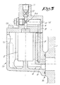
- Figure 3 shows a practical embodiment of the variant according to figure 2.
- the return line 8, the chamber 9, the outlet 10 and an end portion of the part 3 of the line 3-4 are integrated in a component 13 in the shape of a small pot.
- the pressure regulator 12, the ejector 5A, the part 4 of the line 3-4 and the remainder of the part 3 are integrated in a second component 14 in the shape of a lid which is fixed to the component 13 by means of a bolt fastening 15.
Landscapes
- Engineering & Computer Science (AREA)
- Mechanical Engineering (AREA)
- General Engineering & Computer Science (AREA)
- Filtering Of Dispersed Particles In Gases (AREA)
- Compressor (AREA)
- Applications Or Details Of Rotary Compressors (AREA)
- Electrical Discharge Machining, Electrochemical Machining, And Combined Machining (AREA)
- Lubrication Details And Ventilation Of Internal Combustion Engines (AREA)
Claims (5)
- Ölbehälter (1) mit Entlüftungssystem, das einen Ölabscheidefilter (2), der mittels einer Entlüftungsleitung (3-4) mit dem Ölbehälter verbunden ist, und eine in der Entlüftungsleitung (3-4) installierte Saugpumpe (5-5a) zum Ansaugen ölbelasteter Luft aus dem Ölbehälter (1) umfasst, wobei der Ölbehälter (1) mittels einer ständigen Fluidverbindung (6) mit der Umgebung verbunden ist, dadurch gekennzeichnet, dass der Filter (2) in einer Kammer (9) montiert ist, die mit einem Luftauslass (10) versehen ist und die mittels einer Rückführleitung (8), die mit zumindest einem Teil der ständigen Fluidleitung (6), welche eine freie Verbindung ist, zusammenfällt, mit dem Ölbehälter (1) verbunden ist.
- Ölbehälter (1) gemäß Anspruch 1, dadurch gekennzeichnet, dass die Saugpumpe (5) ein Ejektor (5A) ist, an den eine Druckluftleitung (11) angeschlossen ist, wobei die Entlüftungsleitung (3-4) einen Teil (3) zwischen dem Unterdruckteil des Ejektors (5A) und dem Ölbehälter (1) und einen Teil (4) zwischen dem Auslass des Ejektors (5A) und dem Filter (2) umfasst.
- Ölbehälter (1) mit Entlüftungssystem gemäß Anspruch 2, dadurch gekennzeichnet, dass ein Druckregler oder eine Begrenzungsvorrichtung (12) in der Druckluftleitung (11) montiert ist.
- Ölbehälter mit Entlüftungssystem gemäß den Ansprüchen 2 und 3, dadurch gekennzeichnet, dass die Rückführleitung (8), die Kammer (9) mit dem Auslass (10) und der am Ölbehälter (1) angeschlossene Endbereich der Entlüftungsleitung (3-4) in einem ersten Bauteil (13) integriert sind, während der Druckregler (12), der Ejektor (5A) und der Rest der Entlüftungsleitung (3-4) in einem zweiten Bauteil (14) integriert sind, das mittels einer Verbindung (15) mit dem ersten Bauteil (13) verbunden ist.
- Ölbehälter mit Entlüftungssystem gemäß einem der Ansprüche 2 bis 4, dadurch gekennzeichnet, dass die Druckluftleitung (11) an das Druckluftnetz einer Druckluftquelle angeschlossen ist.
Applications Claiming Priority (2)
| Application Number | Priority Date | Filing Date | Title |
|---|---|---|---|
| BE9401167A BE1009008A3 (nl) | 1994-12-27 | 1994-12-27 | Inrichting voor het afscheiden van olie uit een ontluchting van een oliereservoir. |
| BE9401167 | 1994-12-27 |
Publications (2)
| Publication Number | Publication Date |
|---|---|
| EP0719910A1 EP0719910A1 (de) | 1996-07-03 |
| EP0719910B1 true EP0719910B1 (de) | 2001-08-01 |
Family
ID=3888555
Family Applications (1)
| Application Number | Title | Priority Date | Filing Date |
|---|---|---|---|
| EP95203621A Expired - Lifetime EP0719910B1 (de) | 1994-12-27 | 1995-12-22 | Vorrichtung zum Abscheiden von Öl aus einer Öltankentlüftungsleitung |
Country Status (8)
| Country | Link |
|---|---|
| US (1) | US5681372A (de) |
| EP (1) | EP0719910B1 (de) |
| JP (1) | JP3949742B2 (de) |
| KR (1) | KR100363453B1 (de) |
| AT (1) | ATE203799T1 (de) |
| BE (1) | BE1009008A3 (de) |
| DE (1) | DE69521980T2 (de) |
| ES (1) | ES2161824T3 (de) |
Families Citing this family (16)
| Publication number | Priority date | Publication date | Assignee | Title |
|---|---|---|---|---|
| US20040022788A1 (en) | 1998-05-19 | 2004-02-05 | Moser Tammy L. | Compositions and methods for promoting or inhibiting angiogenesis |
| CA2332507A1 (en) | 1998-05-19 | 1999-11-25 | Duke University | Angiostatin receptor |
| US6152120A (en) * | 1999-06-04 | 2000-11-28 | Caterpillar Inc. | Diesel engine system with oil-air separator and method of operation |
| JP4003378B2 (ja) * | 2000-06-30 | 2007-11-07 | 株式会社日立プラントテクノロジー | スクリュー圧縮機 |
| US7255986B2 (en) * | 2002-01-31 | 2007-08-14 | The Board Of Trustees Operating Michigan State University | Compositions for the diagnosis and treatment of epizootic catarrhal enteritis in ferrets |
| US20080072883A1 (en) * | 2004-07-06 | 2008-03-27 | Brancato David M | Motorcycle crankcase ventilation reservoir and dissipator |
| BE1016301A3 (nl) * | 2004-11-08 | 2006-07-04 | Atlas Copco Airpower Nv | Inrichting voor het afscheiden van olie uit een ontluchting van een oliereservoir. |
| DE202008005363U1 (de) * | 2008-04-17 | 2009-09-03 | Mann+Hummel Gmbh | Kurbelgehäuseentlüftung einer Brennkraftmaschine |
| KR101010335B1 (ko) * | 2008-07-25 | 2011-01-25 | 삼성중공업 주식회사 | 오일 미스트 벤트 구조 |
| US9856866B2 (en) | 2011-01-28 | 2018-01-02 | Wabtec Holding Corp. | Oil-free air compressor for rail vehicles |
| US10843113B2 (en) | 2016-11-01 | 2020-11-24 | Ingersoll-Rand Industrial U.S., Inc. | Cyclonic oil separator for compressor oil reservoir |
| CN107061967B (zh) * | 2016-12-14 | 2023-07-04 | 中山益能达精密电子有限公司 | 真空吸油泵 |
| DE102017128483A1 (de) * | 2017-11-30 | 2019-06-06 | Rolls-Royce Deutschland Ltd & Co Kg | Flugtriebwerk |
| DE102018211760B4 (de) * | 2018-07-13 | 2021-03-18 | BRUSS Sealing Systems GmbH | System zur Kurbelgehäuseentlüftung eines Verbrennungsmotors |
| DE102021111051B4 (de) | 2021-04-29 | 2022-12-29 | BRUSS Sealing Systems GmbH | Entlüftungsvorrichtung |
| DE102021116925A1 (de) | 2021-06-30 | 2023-01-05 | Kaeser Kompressoren Se | Trockenverdichtender Verdichter und Verfahren zur Ölabscheidung für einen trockenverdichtenden Verdichter |
Family Cites Families (15)
| Publication number | Priority date | Publication date | Assignee | Title |
|---|---|---|---|---|
| US1781638A (en) * | 1929-06-26 | 1930-11-11 | Ohn L Green | Fluid air cleaner |
| US2029216A (en) * | 1934-11-15 | 1936-01-28 | George A Barker | Crank case ventilation |
| US2686504A (en) * | 1951-01-24 | 1954-08-17 | Hill Walter Pearl | Filter for engine crankcases |
| US3016977A (en) * | 1959-01-26 | 1962-01-16 | Thompson Ramo Wooldridge Inc | Oil tank assembly |
| US3246639A (en) * | 1964-10-09 | 1966-04-19 | John J Oliver | Smog control device |
| US3378104A (en) * | 1966-03-08 | 1968-04-16 | Gen Electric | Air-oil separators for use in gas turbine engines |
| US3509967A (en) * | 1967-10-24 | 1970-05-05 | Paul K Ballard | System for treating crankcase vapors in automotive engines |
| US3633341A (en) * | 1970-06-03 | 1972-01-11 | American Standard Inc | Oil mist eliminator for a fluid drive |
| NO782560L (no) * | 1977-10-24 | 1979-04-25 | Semt | Fremgangsmaate til fjernelse av oljedamper i veivkassen paa en forbrenningsmotor og anordning til utfoerelse av fremgangsmaaten |
| US4263029A (en) * | 1979-02-02 | 1981-04-21 | Cego, Inc. | Oil reclaimer and muffler assembly and system |
| FR2455580A1 (fr) * | 1979-05-04 | 1980-11-28 | Propylox Sa | Procede pour l'epuration de solutions organiques de peracides carboxyliques |
| JPS6010813U (ja) * | 1983-06-30 | 1985-01-25 | 株式会社クボタ | エンジンのブロ−バイガスの燃焼室還元装置 |
| DE3445052A1 (de) * | 1984-12-11 | 1986-06-26 | Rotorcomp Verdichter GmbH, 8000 München | Vorrichtung zum entgasen einer mittels eines fluidabscheiders separierten fluessigphase |
| CH675278A5 (de) * | 1988-02-25 | 1990-09-14 | Burckhardt Ag Maschf | |
| US5503659A (en) * | 1994-08-11 | 1996-04-02 | Crosman; Jay C. | Ventguard |
-
1994
- 1994-12-27 BE BE9401167A patent/BE1009008A3/nl not_active IP Right Cessation
-
1995
- 1995-12-22 EP EP95203621A patent/EP0719910B1/de not_active Expired - Lifetime
- 1995-12-22 AT AT95203621T patent/ATE203799T1/de active
- 1995-12-22 DE DE69521980T patent/DE69521980T2/de not_active Expired - Lifetime
- 1995-12-22 ES ES95203621T patent/ES2161824T3/es not_active Expired - Lifetime
- 1995-12-26 JP JP33884695A patent/JP3949742B2/ja not_active Expired - Lifetime
- 1995-12-27 KR KR1019950058472A patent/KR100363453B1/ko not_active IP Right Cessation
- 1995-12-27 US US08/580,441 patent/US5681372A/en not_active Expired - Lifetime
Also Published As
| Publication number | Publication date |
|---|---|
| JP3949742B2 (ja) | 2007-07-25 |
| BE1009008A3 (nl) | 1996-10-01 |
| KR100363453B1 (ko) | 2003-02-26 |
| KR960021089A (ko) | 1996-07-18 |
| DE69521980T2 (de) | 2002-04-04 |
| ES2161824T3 (es) | 2001-12-16 |
| US5681372A (en) | 1997-10-28 |
| JPH08229325A (ja) | 1996-09-10 |
| ATE203799T1 (de) | 2001-08-15 |
| EP0719910A1 (de) | 1996-07-03 |
| DE69521980D1 (de) | 2001-09-06 |
Similar Documents
| Publication | Publication Date | Title |
|---|---|---|
| EP0719910B1 (de) | Vorrichtung zum Abscheiden von Öl aus einer Öltankentlüftungsleitung | |
| US4615315A (en) | Oil cleaning assemblies for engines | |
| US4354362A (en) | Integral suction line accumulator/filter-drier | |
| US5660607A (en) | Apparatus for separating oil aerosols from air | |
| US4632650A (en) | Vacuum pump having an evacuated gear chamber | |
| US6500243B2 (en) | Compressor system including a separator tank with a separator element positioned therein | |
| MXPA01012763A (es) | Conjunto de filtro con valvula de verificacion y sumidero. | |
| EP0428473B1 (de) | Schmierölrückgewinnungssystem | |
| US8246728B2 (en) | Compressed-air supply device and valve housing | |
| EP1809868B1 (de) | Vorrichtung zum trennen von öl aus einer entlüftung eines ölbehälters | |
| US4131396A (en) | Hermetic compressor lubrication system with two-stage oil pump | |
| JPH01277696A (ja) | オイルフリー・スクリュー圧縮機装置 | |
| US6018962A (en) | Centrifugal compressor oil sump demister apparatus | |
| US20020106287A1 (en) | Air compressor system and an air/oil cast separator tank for the same | |
| EP0500153A2 (de) | System für die Zurückgewinnung des Schmieröls für die Lager eines Kreiselverdichters mit Labyrinthdichtungen | |
| CN218011867U (zh) | 干螺杆空气压缩机用电动油雾回收器和干螺杆空气压缩机 | |
| JP2544435Y2 (ja) | 空気圧縮装置に於ける浄油装置 | |
| JPH0381593A (ja) | オイルフリー・スクリュー圧縮機装置 | |
| US7174917B2 (en) | Inlet piece for a liquid-injected compressor element | |
| JPH01130093A (ja) | 真空ポンプ |
Legal Events
| Date | Code | Title | Description |
|---|---|---|---|
| PUAI | Public reference made under article 153(3) epc to a published international application that has entered the european phase |
Free format text: ORIGINAL CODE: 0009012 |
|
| AK | Designated contracting states |
Kind code of ref document: A1 Designated state(s): AT BE DE ES FR GB IT NL SE |
|
| 17P | Request for examination filed |
Effective date: 19960726 |
|
| 17Q | First examination report despatched |
Effective date: 19980904 |
|
| GRAG | Despatch of communication of intention to grant |
Free format text: ORIGINAL CODE: EPIDOS AGRA |
|
| GRAG | Despatch of communication of intention to grant |
Free format text: ORIGINAL CODE: EPIDOS AGRA |
|
| GRAH | Despatch of communication of intention to grant a patent |
Free format text: ORIGINAL CODE: EPIDOS IGRA |
|
| GRAH | Despatch of communication of intention to grant a patent |
Free format text: ORIGINAL CODE: EPIDOS IGRA |
|
| GRAA | (expected) grant |
Free format text: ORIGINAL CODE: 0009210 |
|
| AK | Designated contracting states |
Kind code of ref document: B1 Designated state(s): AT BE DE ES FR GB IT NL SE |
|
| REF | Corresponds to: |
Ref document number: 203799 Country of ref document: AT Date of ref document: 20010815 Kind code of ref document: T |
|
| REF | Corresponds to: |
Ref document number: 69521980 Country of ref document: DE Date of ref document: 20010906 |
|
| REG | Reference to a national code |
Ref country code: ES Ref legal event code: FG2A Ref document number: 2161824 Country of ref document: ES Kind code of ref document: T3 |
|
| ET | Fr: translation filed | ||
| REG | Reference to a national code |
Ref country code: GB Ref legal event code: IF02 |
|
| PLBE | No opposition filed within time limit |
Free format text: ORIGINAL CODE: 0009261 |
|
| STAA | Information on the status of an ep patent application or granted ep patent |
Free format text: STATUS: NO OPPOSITION FILED WITHIN TIME LIMIT |
|
| 26N | No opposition filed | ||
| PG25 | Lapsed in a contracting state [announced via postgrant information from national office to epo] |
Ref country code: IT Free format text: LAPSE BECAUSE OF NON-PAYMENT OF DUE FEES Effective date: 20051222 |
|
| PGRI | Patent reinstated in contracting state [announced from national office to epo] |
Ref country code: IT Effective date: 20110616 |
|
| PGFP | Annual fee paid to national office [announced via postgrant information from national office to epo] |
Ref country code: GB Payment date: 20141126 Year of fee payment: 20 Ref country code: SE Payment date: 20141126 Year of fee payment: 20 Ref country code: DE Payment date: 20141215 Year of fee payment: 20 |
|
| PGFP | Annual fee paid to national office [announced via postgrant information from national office to epo] |
Ref country code: FR Payment date: 20141120 Year of fee payment: 20 Ref country code: AT Payment date: 20141215 Year of fee payment: 20 Ref country code: NL Payment date: 20141120 Year of fee payment: 20 |
|
| PGFP | Annual fee paid to national office [announced via postgrant information from national office to epo] |
Ref country code: IT Payment date: 20141128 Year of fee payment: 20 |
|
| PGFP | Annual fee paid to national office [announced via postgrant information from national office to epo] |
Ref country code: ES Payment date: 20141230 Year of fee payment: 20 Ref country code: BE Payment date: 20141117 Year of fee payment: 20 |
|
| REG | Reference to a national code |
Ref country code: DE Ref legal event code: R071 Ref document number: 69521980 Country of ref document: DE |
|
| REG | Reference to a national code |
Ref country code: NL Ref legal event code: MK Effective date: 20151221 |
|
| REG | Reference to a national code |
Ref country code: GB Ref legal event code: PE20 Expiry date: 20151221 |
|
| PG25 | Lapsed in a contracting state [announced via postgrant information from national office to epo] |
Ref country code: GB Free format text: LAPSE BECAUSE OF EXPIRATION OF PROTECTION Effective date: 20151221 |
|
| REG | Reference to a national code |
Ref country code: SE Ref legal event code: EUG |
|
| REG | Reference to a national code |
Ref country code: AT Ref legal event code: MK07 Ref document number: 203799 Country of ref document: AT Kind code of ref document: T Effective date: 20151222 |
|
| REG | Reference to a national code |
Ref country code: ES Ref legal event code: FD2A Effective date: 20160331 |
|
| PG25 | Lapsed in a contracting state [announced via postgrant information from national office to epo] |
Ref country code: ES Free format text: LAPSE BECAUSE OF EXPIRATION OF PROTECTION Effective date: 20151223 |