EP0719692A1 - Foldable load handling trolley - Google Patents
Foldable load handling trolley Download PDFInfo
- Publication number
- EP0719692A1 EP0719692A1 EP95402764A EP95402764A EP0719692A1 EP 0719692 A1 EP0719692 A1 EP 0719692A1 EP 95402764 A EP95402764 A EP 95402764A EP 95402764 A EP95402764 A EP 95402764A EP 0719692 A1 EP0719692 A1 EP 0719692A1
- Authority
- EP
- European Patent Office
- Prior art keywords
- base
- upright
- trolley according
- branch
- uprights
- Prior art date
- Legal status (The legal status is an assumption and is not a legal conclusion. Google has not performed a legal analysis and makes no representation as to the accuracy of the status listed.)
- Granted
Links
Images
Classifications
-
- B—PERFORMING OPERATIONS; TRANSPORTING
- B62—LAND VEHICLES FOR TRAVELLING OTHERWISE THAN ON RAILS
- B62B—HAND-PROPELLED VEHICLES, e.g. HAND CARTS OR PERAMBULATORS; SLEDGES
- B62B3/00—Hand carts having more than one axis carrying transport wheels; Steering devices therefor; Equipment therefor
- B62B3/002—Hand carts having more than one axis carrying transport wheels; Steering devices therefor; Equipment therefor characterised by a rectangular shape, involving sidewalls or racks
-
- B—PERFORMING OPERATIONS; TRANSPORTING
- B62—LAND VEHICLES FOR TRAVELLING OTHERWISE THAN ON RAILS
- B62B—HAND-PROPELLED VEHICLES, e.g. HAND CARTS OR PERAMBULATORS; SLEDGES
- B62B2205/00—Hand-propelled vehicles or sledges being foldable or dismountable when not in use
- B62B2205/06—Foldable with a scissor-like mechanism
Definitions
- the present invention relates to a folding handling trolley.
- the trolley is of the type commonly called "roll" used to transport cartons, packages or crates of stacked goods. It generally includes a base mounted on casters, two side walls or drop sides and elastic straps allowing the drop sides to be brought towards each other to improve the resistance of the loads.
- the oldest solution is to provide removable drop sides.
- the sideboards are then stored on one side and, on the other, the bases which can, for example, be stacked on top of each other in an unassembled carriage.
- Another solution has been to provide a pivoting bottom grid, and foldable drop sides against a base having a "Z” shape or a trapezoidal "U” or “A” shape allowing the embedding of another base.
- the present invention aims to provide yet another solution for empty storage of carts.
- It offers a folding handling trolley fitted with casters and a pivoting grid, characterized in that it comprises a cross-shaped base articulated with two branches and two uprights of inverted "U", each upright having a first end portion integral with 'one end of one of the legs of the base and another second end part free and capable of being fixed to one end of the other branch of the base.
- the base can be folded by the tightening of its two branches one against the other.
- the uprights, integral with the base by their respective first end portion are found arranged in generally parallel planes and close to one another.
- the transition from one configuration to another of the carriage therefore takes place in a very simple manner.
- the trolleys in the folded configuration can be stored next to each other in a reduced volume.
- the first terminal parts of each upright are each fixed to a different branch of the base.
- the first terminal parts of each upright are each fixed on the same branch of the base.
- the first makes it possible to manufacture a single model of branch, comprising at one end means for the permanent fixing of the first end part of a first upright and at the other end means for the fixing if necessary of the second end part of the second amount.
- the second construction allows the folded cart to occupy a volume which may be more favorable for storage, in particular by preventing the ends of the legs of the base from protruding.
- the fixing of the second end part of the uprights is effected by fitting into a housing while the fixing of the first end part is effected in a socket in which it is adapted to slide to allow interlocking of the second end part of the base and relative to which it is adapted to pivot to allow the amounts to be brought closer to the base when the latter is folded.
- means are provided for fixing the second end portions of the uprights to the base when the base is folded, comprising locking housings formed on the base adapted to receive said second end parts of the uprights by fitting together.
- the carriage comprises a cross-shaped base 1 with two branches first 5 and second 6 articulated around a central pivot 3 so as to be brought closer to each other as shown in Figure 3, and two side walls or sides 7A, 7B each consisting of an upright 8A, 8B in "U” inverted and a grid of welded longitudinal and transverse son.
- the base 1 is adapted to receive a bottom grid 11 comprising on one side eyelets 13 for articulation on a rod 19B formed at the base of the side panel 7B and on the other hooks 17 adapted to cooperate with a rod 19A formed at the base of the side panel 7A so as to allow the side panels to be locked parallel to one another.
- the first branch 5 of the base comprises a socket known as the first branch 10A, 10B in which is adapted to slide and pivot one of the terminal portions known as the first 12A, 12B of each upright 8A, 8B.
- Means for blocking the sliding of the first end parts 12A, 12B in the sockets 10A, 10B, are provided comprising a thrust washer 18A, 18B provided at the end of each first end part 12A, 12B adapted to block sliding.
- the second branch 6 of the base comprises a socket called the second branch 14A, 14B in which is adapted to fit the other end portion called the second 15A, 15B of the uprights 8A, 8B.
- Means for blocking the nesting of the second end portions 15A, 15B of the uprights 8A, 8B in the sockets 14A, 14B are provided comprising a bottom formed in said sockets 14A, 14B.
- two so-called locking sockets 20A, 20B are formed at a distance from the central articulation point 3 and from the end 6A or 6B of the branch 6 such that, when the carriage is in the storage configuration, as shown in FIG. 3, the second end portions 15A, 15B of the uprights 8A, 8B are capable of being fitted into said locking sockets 20A, 20B.
- Means for blocking the nesting of the second end portions 15A, 15B in said locking housings 20A, 20B are provided.
- first branch sockets 10A, 10B, the second branch sockets 14A, 14B and the locking sockets 20A, 20B are slightly flush with the branches 5 and 6 of the base.
- Each upright 8A, 8B thus has a first end portion 12A, 12B, integral with the base 1 and a second free end portion 15A, 15B capable of being fitted either in the corresponding second branch socket 14A, 14B when the carriage is in configuration as shown in FIG. 1, either in the locking sleeve 20A, 20B when the carriage is in the storage configuration as shown in FIG. 3.
- rollers 22 are fixed under the base 1 at the ends of the branches 5 and 6 slightly set back relative to the bushings of the first and second branches 10A, 10B and 14A, 14B.
- the gate 11 the second end portions 15A, 15B of each upright 8A, 8B are disengaged from the first branch sockets 14A, 14B.
- This operation is made possible by sliding the other end portion 12A, 12B of the upright in the corresponding second branch socket 10A, 10B, the thrust washer 18A preventing the uprights from coming apart.
- the second branch 6 of the base is then free to pivot. It can be brought closer to the first branch 5, then rotate the uprights 8A, 8B in the first branch sockets 10A, 10B and fit the free second end portions 15A, 15B of the uprights in the locking sockets 20A, 20B by sliding again the first terminal parts 12A, 12B in the first branch sockets 10A, 10B.
- the carriage is then locked in the storage position shown in FIG. 3.
Abstract
Description
La présente invention concerne un chariot de manutention repliable.The present invention relates to a folding handling trolley.
Le chariot est du type appelé couramment "roll" servant au transport de cartons, paquets ou cageots de marchandises empilés. Il comporte généralement un socle monté sur des roulettes, deux parois latérales ou ridelles et des sangles élastiques permettant de rapprocher les ridelles l'une vers l'autre pour améliorer la tenue des charges.The trolley is of the type commonly called "roll" used to transport cartons, packages or crates of stacked goods. It generally includes a base mounted on casters, two side walls or drop sides and elastic straps allowing the drop sides to be brought towards each other to improve the resistance of the loads.
On a proposé plusieurs solutions pour ranger les chariots à vide.Several solutions have been proposed for storing vacuum carts.
La solution la plus ancienne consiste à prévoir des ridelles démontables. On stocke alors d'un côté les ridelles et de l'autre, les socles qui peuvent par exemple être empilés les uns sur les autres dans un chariot non démonté.The oldest solution is to provide removable drop sides. The sideboards are then stored on one side and, on the other, the bases which can, for example, be stacked on top of each other in an unassembled carriage.
Une autre solution a été de prévoir une grille de fond pivotante, et des ridelles rabattables contre un socle présentant une forme en "Z" ou une forme trapézoïdale en "U" ou en "A" autorisant l'encastrement d'un autre socle.Another solution has been to provide a pivoting bottom grid, and foldable drop sides against a base having a "Z" shape or a trapezoidal "U" or "A" shape allowing the embedding of another base.
La présente invention a pour but de proposer une autre solution encore pour le rangement à vide des chariots.The present invention aims to provide yet another solution for empty storage of carts.
Elle propose un chariot de manutention repliable muni de roulettes et d'une grille pivotante, caractérisé en ce qu'il comporte un socle en croix articulé à deux branches et deux montants en "U" inversé, chaque montant ayant une partie terminale première solidaire d'une extrémité d'une des branches du socle et une autre partie terminale seconde libre et susceptible d'être fixée à une extrémité de l'autre branche du socle.It offers a folding handling trolley fitted with casters and a pivoting grid, characterized in that it comprises a cross-shaped base articulated with two branches and two uprights of inverted "U", each upright having a first end portion integral with 'one end of one of the legs of the base and another second end part free and capable of being fixed to one end of the other branch of the base.
La fixation des parties terminales secondes des montants au socle bloque l'articulation de ce dernier. Le chariot se trouve alors en configuration de fonctionnement, une grille de fond pouvant être agencée sur le socle.The fixing of the second end portions of the uprights to the base blocks the articulation of the latter. The carriage is then in the operating configuration, a bottom grid being able to be arranged on the base.
Lorsque les parties terminales secondes des montants sont désolidarisées du socle et la grille relevée, l'articulation de ce dernier redevient possible. Le socle peut être plié par le resserrement de ses deux branches l'une contre l'autre. Dans cette configuration repliée du socle, les montants, solidaires du socle par leur partie terminale première respective, se retrouvent disposés dans des plans globalement parallèles et rapprochés l'un de l'autre.When the second end portions of the uprights are detached from the base and the grid raised, the articulation of the latter again becomes possible. The base can be folded by the tightening of its two branches one against the other. In this folded configuration of the base, the uprights, integral with the base by their respective first end portion, are found arranged in generally parallel planes and close to one another.
Le passage d'une configuration à une autre du chariot s'opère donc de manière très simple. Les chariots en configuration repliée peuvent être rangés les uns à côté des autres dans un volume réduit.The transition from one configuration to another of the carriage therefore takes place in a very simple manner. The trolleys in the folded configuration can be stored next to each other in a reduced volume.
Selon un premier mode de réalisation possible, les parties terminales premières de chaque montant sont fixées chacune sur une branche différente du socle.According to a first possible embodiment, the first terminal parts of each upright are each fixed to a different branch of the base.
Selon un second mode de réalisation possible, les parties terminales premières de chaque montant sont fixées chacune sur une même branche du socle.According to a second possible embodiment, the first terminal parts of each upright are each fixed on the same branch of the base.
Ces deux constructions présentent des avantages. La première permet de fabriquer un modèle unique de branche, comprenant à une extrémité des moyens pour la fixation permanente de la partie terminale première d'un premier montant et à l'autre extrémité des moyens pour la fixation le cas échéant de la partie terminale seconde du second montant. La seconde construction permet au chariot replié d'occuper un volume qui peut être plus favorable au rangement, notamment en évitant que des extrémités des branches du socle ne dépassent.These two constructions have advantages. The first makes it possible to manufacture a single model of branch, comprising at one end means for the permanent fixing of the first end part of a first upright and at the other end means for the fixing if necessary of the second end part of the second amount. The second construction allows the folded cart to occupy a volume which may be more favorable for storage, in particular by preventing the ends of the legs of the base from protruding.
Suivant d'autres caractéristiques, la fixation de la partie terminale seconde des montants s'opère par emboîtement dans un logement tandis que la fixation de la partie terminale première s'opère dans une douille dans laquelle elle est adaptée à coulisser pour permettre l'emboîtement de la partie terminale seconde du socle et par rapport à laquelle elle est adaptée à pivoter pour permettre le rapprochement des montants vers le socle lorsque ce dernier est replié.According to other characteristics, the fixing of the second end part of the uprights is effected by fitting into a housing while the fixing of the first end part is effected in a socket in which it is adapted to slide to allow interlocking of the second end part of the base and relative to which it is adapted to pivot to allow the amounts to be brought closer to the base when the latter is folded.
Selon une autre disposition encore, des moyens sont prévus pour fixer au socle les parties terminales secondes des montants lorsque le socle est replié, comprenant des logements de verrouillage ménagés sur le socle adaptés à recevoir par emboîtement lesdites parties terminales secondes des montants.According to yet another arrangement, means are provided for fixing the second end portions of the uprights to the base when the base is folded, comprising locking housings formed on the base adapted to receive said second end parts of the uprights by fitting together.
La présente invention sera mieux comprise et d'autres avantages apparaîtront à la lumière de la description qui va suivre d'un exemple de réalisation, description faite en référence aux dessins annexés sur lesquels :
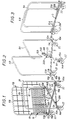
- la figure 1 est une vue schématique en perspective montrant le chariot en configuration de fonctionnement avec la grille en position relevée ;
- la figure 2 est une vue similaire à la figure 1 illustrant une phase intermédiaire du passage à la configuration de rangement du chariot ; et
- la figure 3 est une vue similaire également montrant le chariot en configuration de rangement.
- Figure 1 is a schematic perspective view showing the carriage in operating configuration with the grid in the raised position;
- Figure 2 is a view similar to Figure 1 illustrating an intermediate phase of the transition to the storage configuration of the carriage; and
- Figure 3 is a similar view also showing the trolley in storage configuration.
Selon l'exemple de réalisation représenté sur les figures, le chariot comprend un socle 1 en croix avec deux branches première 5 et seconde 6 articulées autour d'un pivot central 3 de manière à être rapprochées l'une de l'autre comme représenté sur la figure 3, et deux parois latérales ou ridelles 7A, 7B constituées chacune d'un montant 8A, 8B en "U" inversé et d'un quadrillage de fils soudés longitudinaux et transversaux. Le socle 1 est adapté à recevoir une grille de fond 11 comprenant d'un côté des oeillets 13 d'articulation sur une tige 19B ménagée à la base de la ridelle 7B et de l'autre des crochets 17 adaptés à coopérer avec une tige 19A ménagée à la base de la ridelle 7A de manière à permettre le verrouillage des ridelles parallèles l'une à l'autre.According to the embodiment shown in the figures, the carriage comprises a cross-shaped base 1 with two branches first 5 and second 6 articulated around a
Pour faciliter la lecture de la figure 1, le quadrillage de fils soudés des ridelles est représenté partiellement seulement et la grille de fond 11 est représentée en position relevée. Par ailleurs pour alléger les figures 2 et 3, ces éléments n'ont pas été représentés.To facilitate reading of Figure 1, the grid of welded sidewalls is shown only partially and the
A chacune de ses extrémités 5A, 5B, la première branche 5 du socle comprend une douille dite de première branche 10A, 10B dans laquelle est adaptée à coulisser et à pivoter l'une des parties terminales dite première 12A, 12B de chaque montant 8A, 8B. Des moyens de blocage du coulissement des parties terminales premières 12A, 12B dans les douilles 10A, 10B, sont prévus comprenant une rondelle de butée 18A, 18B prévue à l'extrémité de chaque partie terminale première 12A, 12B adaptée à bloquer le coulissement.At each of its
A chacune de ses extrémités 6A, 6B, la seconde branche 6 du socle comprend une douille dite de seconde branche 14A, 14B dans laquelle est adaptée à s'emboîter l'autre partie terminale dite seconde 15A, 15B des montants 8A, 8B. Des moyens de blocage de l'emboîtement des parties terminales secondes 15A, 15B des montants 8A, 8B dans les douilles 14A, 14B sont prévus comprenant un fond ménagé dans lesdites douilles 14A, 14B.At each of its
Le long de la seconde branche 6 du socle, sur les bords opposés de celle-ci, sont ménagées deux douilles dites de verrouillage 20A, 20B à une distance du point d'articulation central 3 et de l'extrémité 6A ou 6B de la branche 6 telle que, lorsque le chariot est en configuration de rangement, comme représenté sur la figure 3, les parties terminales secondes 15A, 15B des montants 8A, 8B sont susceptibles d'être emboîtées dans lesdites douilles de verrouillage 20A, 20B. Des moyens de blocage de l'emboîtement des parties terminales secondes 15A, 15B dans lesdits logements de verrouillage 20A, 20B sont prévus.Along the second branch 6 of the base, on the opposite edges of the latter, two so-called
Les extrémités supérieures des douilles de première branche 10A, 10B, des douilles de seconde branche 14A, 14B et des douilles de verrouillage 20A, 20B affleurent légèrement au dessus des branches 5 et 6 du socle.The upper ends of the
Chaque montant 8A, 8B possède ainsi une partie terminale première 12A, 12B, solidaire du socle 1 et une partie terminale seconde libre 15A, 15B susceptible d'être emboîtée soit dans la douille de seconde branche correspondante 14A, 14B lorsque le chariot est en configuration de fonctionnement comme représenté à la figure 1, soit dans la douille de verrouillage 20A, 20B lorsque le chariot est en configuration de rangement comme représenté à la figure 3.Each upright 8A, 8B thus has a
Quatre roulettes 22 sont fixées sous le socle 1 aux extrémités des branches 5 et 6 légèrement en retrait par rapport aux douilles de première et seconde branches 10A, 10B et 14A, 14B.Four
Le chariot se plie de la manière suivante. On relève la grille 11, les parties terminales secondes 15A, 15B de chaque montant 8A, 8B sont déboîtées des douilles de première branche 14A, 14B. Cette opération est rendue possible grâce au coulissement de l'autre partie terminale 12A, 12B du montant dans la douille de seconde branche correspondante 10A, 10B, la rondelle de butée 18A empêchant la désolidarisation des montants. Comme on le voit sur la figure 2, la branche seconde 6 du socle est alors libre de pivoter. On peut la rapprocher de la branche première 5, puis faire pivoter les montants 8A, 8B dans les douilles de première branche 10A, 10B et emboîter les parties terminales secondes libres 15A, 15B des montants dans les douilles de verrouillage 20A, 20B en faisant coulisser à nouveau les parties terminales premières 12A, 12B dans les douilles de première branche 10A, 10B. Le chariot se trouve alors verrouillé dans la position de rangement représentée à la figure 3.The cart folds as follows. We note the
Il va de soi que des variantes de réalisation sont possibles, notamment on peut concevoir que la fixation du montant 8A soit inversée, la fixation de la partie terminale première 12A s'effectuant à l'extrémité 6A de la branche 6 et l'emboîtement de la partie terminale seconde 15A s'effectuant à l'extrémité 5A de la branche 5. La douille de verrouillage 20A pourra être disposée sur la branche 5 entre le pivot central 3 et l'extrémité 5A de la branche 5. Cette construction permet avantageusement d'avoir un seul modèle de branche pour le socle.It goes without saying that alternative embodiments are possible, in particular it is conceivable that the fixing of the upright 8A is reversed, the fixing of the
On peut par ailleurs mettre en oeuvre d'autres moyens de fixation et de pivotement des montants sur les branches du socle.It is also possible to use other means of fixing and pivoting the uprights on the legs of the base.
Claims (11)
Applications Claiming Priority (2)
| Application Number | Priority Date | Filing Date | Title |
|---|---|---|---|
| FR9415851 | 1994-12-29 | ||
| FR9415851A FR2728858B1 (en) | 1994-12-29 | 1994-12-29 | FOLDABLE HANDLING TROLLEY |
Publications (2)
| Publication Number | Publication Date |
|---|---|
| EP0719692A1 true EP0719692A1 (en) | 1996-07-03 |
| EP0719692B1 EP0719692B1 (en) | 1998-09-02 |
Family
ID=9470398
Family Applications (1)
| Application Number | Title | Priority Date | Filing Date |
|---|---|---|---|
| EP19950402764 Expired - Lifetime EP0719692B1 (en) | 1994-12-29 | 1995-12-07 | Foldable load handling trolley |
Country Status (6)
| Country | Link |
|---|---|
| EP (1) | EP0719692B1 (en) |
| DE (1) | DE69504467T2 (en) |
| DK (1) | DK0719692T3 (en) |
| ES (1) | ES2121315T3 (en) |
| FR (1) | FR2728858B1 (en) |
| NO (1) | NO301813B1 (en) |
Citations (4)
| Publication number | Priority date | Publication date | Assignee | Title |
|---|---|---|---|---|
| US2186368A (en) * | 1938-08-31 | 1940-01-09 | Herbert A Conger | Commodity carrier |
| DE1087568B (en) * | 1957-07-04 | 1960-08-25 | Alfred Diele K G Organisations | Chassis for file boxes |
| FR2122009A5 (en) * | 1971-01-14 | 1972-08-25 | Morari Sa | |
| FR2596349A1 (en) * | 1986-03-25 | 1987-10-02 | Meunier Carus Jean Claude | Foldable storage, stowage, transport or handling appliance |
-
1994
- 1994-12-29 FR FR9415851A patent/FR2728858B1/en not_active Expired - Fee Related
-
1995
- 1995-12-07 EP EP19950402764 patent/EP0719692B1/en not_active Expired - Lifetime
- 1995-12-07 ES ES95402764T patent/ES2121315T3/en not_active Expired - Lifetime
- 1995-12-07 DK DK95402764T patent/DK0719692T3/en active
- 1995-12-07 DE DE1995604467 patent/DE69504467T2/en not_active Expired - Fee Related
- 1995-12-28 NO NO955331A patent/NO301813B1/en not_active IP Right Cessation
Patent Citations (4)
| Publication number | Priority date | Publication date | Assignee | Title |
|---|---|---|---|---|
| US2186368A (en) * | 1938-08-31 | 1940-01-09 | Herbert A Conger | Commodity carrier |
| DE1087568B (en) * | 1957-07-04 | 1960-08-25 | Alfred Diele K G Organisations | Chassis for file boxes |
| FR2122009A5 (en) * | 1971-01-14 | 1972-08-25 | Morari Sa | |
| FR2596349A1 (en) * | 1986-03-25 | 1987-10-02 | Meunier Carus Jean Claude | Foldable storage, stowage, transport or handling appliance |
Also Published As
| Publication number | Publication date |
|---|---|
| NO955331D0 (en) | 1995-12-28 |
| FR2728858A1 (en) | 1996-07-05 |
| EP0719692B1 (en) | 1998-09-02 |
| NO955331L (en) | 1996-07-01 |
| DK0719692T3 (en) | 1999-06-07 |
| DE69504467D1 (en) | 1998-10-08 |
| FR2728858B1 (en) | 1997-03-14 |
| DE69504467T2 (en) | 1999-05-06 |
| ES2121315T3 (en) | 1998-11-16 |
| NO301813B1 (en) | 1997-12-15 |
Similar Documents
| Publication | Publication Date | Title |
|---|---|---|
| EP1227945B1 (en) | Coupling device for industrial truck | |
| FR2546466A1 (en) | MANUAL MULTI-PURPOSE TROLLEY WITH MOBILE WHEELS | |
| FR2586988A1 (en) | FOLDING UTILITY CART | |
| EP1023232B1 (en) | Bag for transporting and intermediate storing of bulk goods | |
| FR2473895A1 (en) | CONVERTIBLE TOY VEHICLE FOR CARRYING OVERHEAD LOADS | |
| EP0719692B1 (en) | Foldable load handling trolley | |
| FR2701690A1 (en) | Folding box | |
| JP3903253B2 (en) | Transport folding container | |
| FR2770479A1 (en) | Foldable manual transport trolley for containers | |
| WO1994014684A1 (en) | Six-sided collapsible parallelepiped container | |
| FR2788481A3 (en) | Safety device for collapsible toy pushchair | |
| FR2953479A1 (en) | Device for displacing movable containers e.g. bulky dustbins, in carriages with motorized tractors to transport plates, has gate elements movable in closing position in which gate elements constrain container in device | |
| EP0719691A1 (en) | Nestable load handling trolley | |
| JP2729925B2 (en) | Hand truck | |
| EP0856450A1 (en) | Arrangement for the fixing of loads on a load-carrying vehicle | |
| FR2561601A1 (en) | Trolley of the ''barrow'' type for transporting objects such as suitcases | |
| EP0807542A1 (en) | Load-handling trolleywith fastening means | |
| BE1008758A3 (en) | Folding trolley for freight transport. | |
| EP0407274A1 (en) | Bridging system enabling vehicles to bridge gaps | |
| EP1749729A1 (en) | Stroller with folding handles | |
| BE882189A (en) | DEVICE FOR ASSEMBLING TWO ELEMENTS IN A REMOVABLE WAY FOR THE PLATFORM OF A TRUCK OR LIKE VEHICLE | |
| EP1097656A1 (en) | Table-type having at least one foldable foot or underframe | |
| FR2733727A1 (en) | UTILITY VEHICLE INCLUDING A COVER WITH A MOBILE RANCHER | |
| FR2732314A1 (en) | Transport container assembly | |
| CA2127949C (en) | Get-in ramp |
Legal Events
| Date | Code | Title | Description |
|---|---|---|---|
| PUAI | Public reference made under article 153(3) epc to a published international application that has entered the european phase |
Free format text: ORIGINAL CODE: 0009012 |
|
| AK | Designated contracting states |
Kind code of ref document: A1 Designated state(s): BE CH DE DK ES GB IT LI LU NL SE |
|
| 17P | Request for examination filed |
Effective date: 19960731 |
|
| TPAD | Observations filed by third parties |
Free format text: ORIGINAL CODE: EPIDOS TIPA |
|
| GRAG | Despatch of communication of intention to grant |
Free format text: ORIGINAL CODE: EPIDOS AGRA |
|
| GRAG | Despatch of communication of intention to grant |
Free format text: ORIGINAL CODE: EPIDOS AGRA |
|
| GRAH | Despatch of communication of intention to grant a patent |
Free format text: ORIGINAL CODE: EPIDOS IGRA |
|
| 17Q | First examination report despatched |
Effective date: 19980123 |
|
| GRAH | Despatch of communication of intention to grant a patent |
Free format text: ORIGINAL CODE: EPIDOS IGRA |
|
| GRAA | (expected) grant |
Free format text: ORIGINAL CODE: 0009210 |
|
| AK | Designated contracting states |
Kind code of ref document: B1 Designated state(s): BE CH DE DK ES GB IT LI LU NL SE |
|
| REG | Reference to a national code |
Ref country code: CH Ref legal event code: NV Representative=s name: E. BLUM & CO. PATENTANWAELTE Ref country code: CH Ref legal event code: EP |
|
| REF | Corresponds to: |
Ref document number: 69504467 Country of ref document: DE Date of ref document: 19981008 |
|
| REG | Reference to a national code |
Ref country code: ES Ref legal event code: FG2A Ref document number: 2121315 Country of ref document: ES Kind code of ref document: T3 |
|
| GBT | Gb: translation of ep patent filed (gb section 77(6)(a)/1977) |
Effective date: 19981201 |
|
| REG | Reference to a national code |
Ref country code: DK Ref legal event code: T3 |
|
| PLBE | No opposition filed within time limit |
Free format text: ORIGINAL CODE: 0009261 |
|
| STAA | Information on the status of an ep patent application or granted ep patent |
Free format text: STATUS: NO OPPOSITION FILED WITHIN TIME LIMIT |
|
| 26N | No opposition filed | ||
| PGFP | Annual fee paid to national office [announced via postgrant information from national office to epo] |
Ref country code: SE Payment date: 20001117 Year of fee payment: 6 |
|
| PGFP | Annual fee paid to national office [announced via postgrant information from national office to epo] |
Ref country code: NL Payment date: 20001120 Year of fee payment: 6 Ref country code: DK Payment date: 20001120 Year of fee payment: 6 |
|
| PGFP | Annual fee paid to national office [announced via postgrant information from national office to epo] |
Ref country code: GB Payment date: 20001201 Year of fee payment: 6 |
|
| PGFP | Annual fee paid to national office [announced via postgrant information from national office to epo] |
Ref country code: ES Payment date: 20001212 Year of fee payment: 6 Ref country code: CH Payment date: 20001212 Year of fee payment: 6 |
|
| PGFP | Annual fee paid to national office [announced via postgrant information from national office to epo] |
Ref country code: DE Payment date: 20001214 Year of fee payment: 6 |
|
| PGFP | Annual fee paid to national office [announced via postgrant information from national office to epo] |
Ref country code: BE Payment date: 20001228 Year of fee payment: 6 |
|
| PGFP | Annual fee paid to national office [announced via postgrant information from national office to epo] |
Ref country code: LU Payment date: 20010102 Year of fee payment: 6 |
|
| PG25 | Lapsed in a contracting state [announced via postgrant information from national office to epo] |
Ref country code: LU Free format text: LAPSE BECAUSE OF NON-PAYMENT OF DUE FEES Effective date: 20011207 Ref country code: GB Free format text: LAPSE BECAUSE OF NON-PAYMENT OF DUE FEES Effective date: 20011207 Ref country code: DK Free format text: LAPSE BECAUSE OF NON-PAYMENT OF DUE FEES Effective date: 20011207 |
|
| PG25 | Lapsed in a contracting state [announced via postgrant information from national office to epo] |
Ref country code: SE Free format text: LAPSE BECAUSE OF NON-PAYMENT OF DUE FEES Effective date: 20011208 |
|
| PG25 | Lapsed in a contracting state [announced via postgrant information from national office to epo] |
Ref country code: LI Free format text: LAPSE BECAUSE OF NON-PAYMENT OF DUE FEES Effective date: 20011231 Ref country code: CH Free format text: LAPSE BECAUSE OF NON-PAYMENT OF DUE FEES Effective date: 20011231 Ref country code: BE Free format text: LAPSE BECAUSE OF NON-PAYMENT OF DUE FEES Effective date: 20011231 |
|
| REG | Reference to a national code |
Ref country code: GB Ref legal event code: IF02 |
|
| BERE | Be: lapsed |
Owner name: ATELIERS REUNIS CADDIE Effective date: 20011231 |
|
| PG25 | Lapsed in a contracting state [announced via postgrant information from national office to epo] |
Ref country code: NL Free format text: LAPSE BECAUSE OF NON-PAYMENT OF DUE FEES Effective date: 20020701 |
|
| PG25 | Lapsed in a contracting state [announced via postgrant information from national office to epo] |
Ref country code: DE Free format text: LAPSE BECAUSE OF NON-PAYMENT OF DUE FEES Effective date: 20020702 |
|
| EUG | Se: european patent has lapsed |
Ref document number: 95402764.5 |
|
| GBPC | Gb: european patent ceased through non-payment of renewal fee |
Effective date: 20011207 |
|
| REG | Reference to a national code |
Ref country code: CH Ref legal event code: PL |
|
| NLV4 | Nl: lapsed or anulled due to non-payment of the annual fee |
Effective date: 20020701 |
|
| REG | Reference to a national code |
Ref country code: DK Ref legal event code: EBP |
|
| PG25 | Lapsed in a contracting state [announced via postgrant information from national office to epo] |
Ref country code: ES Free format text: LAPSE BECAUSE OF NON-PAYMENT OF DUE FEES Effective date: 20021208 |
|
| REG | Reference to a national code |
Ref country code: ES Ref legal event code: FD2A Effective date: 20030113 |
|
| PG25 | Lapsed in a contracting state [announced via postgrant information from national office to epo] |
Ref country code: IT Free format text: LAPSE BECAUSE OF NON-PAYMENT OF DUE FEES;WARNING: LAPSES OF ITALIAN PATENTS WITH EFFECTIVE DATE BEFORE 2007 MAY HAVE OCCURRED AT ANY TIME BEFORE 2007. THE CORRECT EFFECTIVE DATE MAY BE DIFFERENT FROM THE ONE RECORDED. Effective date: 20051207 |