EP0719624B1 - A resin molding machine and a method of resin molding - Google Patents
A resin molding machine and a method of resin molding Download PDFInfo
- Publication number
- EP0719624B1 EP0719624B1 EP95308257A EP95308257A EP0719624B1 EP 0719624 B1 EP0719624 B1 EP 0719624B1 EP 95308257 A EP95308257 A EP 95308257A EP 95308257 A EP95308257 A EP 95308257A EP 0719624 B1 EP0719624 B1 EP 0719624B1
- Authority
- EP
- European Patent Office
- Prior art keywords
- resin
- release film
- pot
- molding
- dies
- Prior art date
- Legal status (The legal status is an assumption and is not a legal conclusion. Google has not performed a legal analysis and makes no representation as to the accuracy of the status listed.)
- Expired - Lifetime
Links
Images


Classifications
-
- B—PERFORMING OPERATIONS; TRANSPORTING
- B29—WORKING OF PLASTICS; WORKING OF SUBSTANCES IN A PLASTIC STATE IN GENERAL
- B29C—SHAPING OR JOINING OF PLASTICS; SHAPING OF MATERIAL IN A PLASTIC STATE, NOT OTHERWISE PROVIDED FOR; AFTER-TREATMENT OF THE SHAPED PRODUCTS, e.g. REPAIRING
- B29C45/00—Injection moulding, i.e. forcing the required volume of moulding material through a nozzle into a closed mould; Apparatus therefor
- B29C45/14—Injection moulding, i.e. forcing the required volume of moulding material through a nozzle into a closed mould; Apparatus therefor incorporating preformed parts or layers, e.g. injection moulding around inserts or for coating articles
- B29C45/14639—Injection moulding, i.e. forcing the required volume of moulding material through a nozzle into a closed mould; Apparatus therefor incorporating preformed parts or layers, e.g. injection moulding around inserts or for coating articles for obtaining an insulating effect, e.g. for electrical components
- B29C45/14655—Injection moulding, i.e. forcing the required volume of moulding material through a nozzle into a closed mould; Apparatus therefor incorporating preformed parts or layers, e.g. injection moulding around inserts or for coating articles for obtaining an insulating effect, e.g. for electrical components connected to or mounted on a carrier, e.g. lead frame
-
- B—PERFORMING OPERATIONS; TRANSPORTING
- B29—WORKING OF PLASTICS; WORKING OF SUBSTANCES IN A PLASTIC STATE IN GENERAL
- B29C—SHAPING OR JOINING OF PLASTICS; SHAPING OF MATERIAL IN A PLASTIC STATE, NOT OTHERWISE PROVIDED FOR; AFTER-TREATMENT OF THE SHAPED PRODUCTS, e.g. REPAIRING
- B29C45/00—Injection moulding, i.e. forcing the required volume of moulding material through a nozzle into a closed mould; Apparatus therefor
- B29C45/14—Injection moulding, i.e. forcing the required volume of moulding material through a nozzle into a closed mould; Apparatus therefor incorporating preformed parts or layers, e.g. injection moulding around inserts or for coating articles
-
- B—PERFORMING OPERATIONS; TRANSPORTING
- B29—WORKING OF PLASTICS; WORKING OF SUBSTANCES IN A PLASTIC STATE IN GENERAL
- B29C—SHAPING OR JOINING OF PLASTICS; SHAPING OF MATERIAL IN A PLASTIC STATE, NOT OTHERWISE PROVIDED FOR; AFTER-TREATMENT OF THE SHAPED PRODUCTS, e.g. REPAIRING
- B29C33/00—Moulds or cores; Details thereof or accessories therefor
- B29C33/0038—Moulds or cores; Details thereof or accessories therefor with sealing means or the like
-
- B—PERFORMING OPERATIONS; TRANSPORTING
- B29—WORKING OF PLASTICS; WORKING OF SUBSTANCES IN A PLASTIC STATE IN GENERAL
- B29C—SHAPING OR JOINING OF PLASTICS; SHAPING OF MATERIAL IN A PLASTIC STATE, NOT OTHERWISE PROVIDED FOR; AFTER-TREATMENT OF THE SHAPED PRODUCTS, e.g. REPAIRING
- B29C33/00—Moulds or cores; Details thereof or accessories therefor
- B29C33/56—Coatings, e.g. enameled or galvanised; Releasing, lubricating or separating agents
- B29C33/68—Release sheets
-
- B—PERFORMING OPERATIONS; TRANSPORTING
- B29—WORKING OF PLASTICS; WORKING OF SUBSTANCES IN A PLASTIC STATE IN GENERAL
- B29C—SHAPING OR JOINING OF PLASTICS; SHAPING OF MATERIAL IN A PLASTIC STATE, NOT OTHERWISE PROVIDED FOR; AFTER-TREATMENT OF THE SHAPED PRODUCTS, e.g. REPAIRING
- B29C45/00—Injection moulding, i.e. forcing the required volume of moulding material through a nozzle into a closed mould; Apparatus therefor
- B29C45/17—Component parts, details or accessories; Auxiliary operations
- B29C45/26—Moulds
- B29C45/37—Mould cavity walls, i.e. the inner surface forming the mould cavity, e.g. linings
-
- B—PERFORMING OPERATIONS; TRANSPORTING
- B29—WORKING OF PLASTICS; WORKING OF SUBSTANCES IN A PLASTIC STATE IN GENERAL
- B29C—SHAPING OR JOINING OF PLASTICS; SHAPING OF MATERIAL IN A PLASTIC STATE, NOT OTHERWISE PROVIDED FOR; AFTER-TREATMENT OF THE SHAPED PRODUCTS, e.g. REPAIRING
- B29C70/00—Shaping composites, i.e. plastics material comprising reinforcements, fillers or preformed parts, e.g. inserts
- B29C70/68—Shaping composites, i.e. plastics material comprising reinforcements, fillers or preformed parts, e.g. inserts by incorporating or moulding on preformed parts, e.g. inserts or layers, e.g. foam blocks
- B29C70/72—Encapsulating inserts having non-encapsulated projections, e.g. extremities or terminal portions of electrical components
-
- H—ELECTRICITY
- H01—ELECTRIC ELEMENTS
- H01L—SEMICONDUCTOR DEVICES NOT COVERED BY CLASS H10
- H01L21/00—Processes or apparatus adapted for the manufacture or treatment of semiconductor or solid state devices or of parts thereof
-
- B—PERFORMING OPERATIONS; TRANSPORTING
- B29—WORKING OF PLASTICS; WORKING OF SUBSTANCES IN A PLASTIC STATE IN GENERAL
- B29C—SHAPING OR JOINING OF PLASTICS; SHAPING OF MATERIAL IN A PLASTIC STATE, NOT OTHERWISE PROVIDED FOR; AFTER-TREATMENT OF THE SHAPED PRODUCTS, e.g. REPAIRING
- B29C45/00—Injection moulding, i.e. forcing the required volume of moulding material through a nozzle into a closed mould; Apparatus therefor
- B29C45/14—Injection moulding, i.e. forcing the required volume of moulding material through a nozzle into a closed mould; Apparatus therefor incorporating preformed parts or layers, e.g. injection moulding around inserts or for coating articles
- B29C45/14639—Injection moulding, i.e. forcing the required volume of moulding material through a nozzle into a closed mould; Apparatus therefor incorporating preformed parts or layers, e.g. injection moulding around inserts or for coating articles for obtaining an insulating effect, e.g. for electrical components
- B29C45/14655—Injection moulding, i.e. forcing the required volume of moulding material through a nozzle into a closed mould; Apparatus therefor incorporating preformed parts or layers, e.g. injection moulding around inserts or for coating articles for obtaining an insulating effect, e.g. for electrical components connected to or mounted on a carrier, e.g. lead frame
- B29C2045/14663—Injection moulding, i.e. forcing the required volume of moulding material through a nozzle into a closed mould; Apparatus therefor incorporating preformed parts or layers, e.g. injection moulding around inserts or for coating articles for obtaining an insulating effect, e.g. for electrical components connected to or mounted on a carrier, e.g. lead frame the mould cavity walls being lined with a film, e.g. release film
-
- B—PERFORMING OPERATIONS; TRANSPORTING
- B29—WORKING OF PLASTICS; WORKING OF SUBSTANCES IN A PLASTIC STATE IN GENERAL
- B29C—SHAPING OR JOINING OF PLASTICS; SHAPING OF MATERIAL IN A PLASTIC STATE, NOT OTHERWISE PROVIDED FOR; AFTER-TREATMENT OF THE SHAPED PRODUCTS, e.g. REPAIRING
- B29C33/00—Moulds or cores; Details thereof or accessories therefor
- B29C33/10—Moulds or cores; Details thereof or accessories therefor with incorporated venting means
Landscapes
- Engineering & Computer Science (AREA)
- Mechanical Engineering (AREA)
- Manufacturing & Machinery (AREA)
- Chemical & Material Sciences (AREA)
- Composite Materials (AREA)
- Condensed Matter Physics & Semiconductors (AREA)
- Physics & Mathematics (AREA)
- General Physics & Mathematics (AREA)
- Computer Hardware Design (AREA)
- Microelectronics & Electronic Packaging (AREA)
- Power Engineering (AREA)
- Injection Moulding Of Plastics Or The Like (AREA)
- Encapsulation Of And Coatings For Semiconductor Or Solid State Devices (AREA)
- Moulds For Moulding Plastics Or The Like (AREA)
- Processing And Handling Of Plastics And Other Materials For Molding In General (AREA)
Description
- The present invention relates to a method of resin molding and a resin molding machine, more precisely relates to a method of resin molding comprising the steps of: providing release film, which is capable of easily peeling off from molding dies and resin, on a parting faces of the molding dies; and clamping a member to be molded by the molding dies together with the release film, and a resin molding machine for executing said method.
- A conventional resin molding machine is shown in Fig. 16. In the conventional machine, a member to be molded is clamped between an
upper die 10a and alower die 10b. Resin heated and melt in apot 12 is pressurized and sent to acavity 14 by aplunger 13. Resin tablets, which are formed by: kneading resin materials; forming the resin kneaded into granule; and compressing the granular resin to form into the tablet shapes, are used as resin for molding. - The resin sent from the
pot 12 directly contacts molding faces of the molding dies, so the molding dies are made of a abrasion-proof metal with enough durability. The conventional molding dies haveejector pins 16, which eject a molded product from the molding dies. - Thermosetting resin, e.g., epoxy resin, phenolic resin, are usually used for the resin molding. Generally, the resin is required to be easily peeled off from the molding dies and to tightly adhere to the member to be molded, e.g.,
a lead frame. However, said required conditions of the resin are mutually contradictory, so that the resin which properly satisfies required conditions is selected. Actually, characteristics of the resin must be one-sided. For example, when one resin, which is capable of very easily peeling off from the molding dies, is used for the molding, the solidified resin is apt to peel off from the member to be molded. - On the other hand, when another resin, which has greater adhering force, is used, the solidified resin is not capable of easily peeling off from the molding dies. And some ejector pins cannot be moved, so that the molded product cannot be ejected from the molding dies. Further, when gates are broken after molding, solidified resin, which is solidified in the gates or runners, is left on a surface of the molded product, eg., a lead frame.
- It would be desirable to be able to provide a method of resin molding for molding said regular products and a resin molding machine for the same, which is capable of making molding quality higher and decreasing manufacturing cost of the products.
- According to one aspect of the present invention there is provided a method of resin molding according to claim 1 comprising the steps of:
- supplying a resin tablet into a pot of molding dies each of which includes an associated cavity;
- clamping a member to be molded between the molding dies, and
- covering at least an inner face of said pot and the inner face of the resin path from the pot to the associated cavity with release film which is capable of easily peeling off from said molding die and from the resin.
-
- In this method, the molding can be executed without using the wrapped resin.
- In the method, the covering step may comprises the steps of:
- covering over the face including a cavity, a cull and a pot with a sheet of the release film; and
- sucking the release film to fix onto a part of the face for clamping the member to be molded, an inner face of the cavity, an inner face of the cull and the inner face of the pot.
-
- And in the method, the covering step may comprises the steps of:
- covering over the face including a cavity, a cull and a pot with a sheet of the release film; and
- sucking the release film to fix onto the face for clamping the member to be molded, an inner face of the cavity and an inner face of the cull;
- providing the resin tablet onto the release film at a position corresponding to the pot; and
- setting the resin tablet in the pot by closing the molding dies.
-
- In the method, the release film may have an accommodating section into which the resin tablet is supplied, and the accommodating section may be formed to correspond to an inner shape of the pot. In this case, unwillful shift of the release film on the molding dies can be prevented.
- In the method, the accommodating section may be formed in the release film before providing the release film on the face of the molding die.
- If the resin tablet is preheated in the accommodating section, and the resin tablet is supplied together with the release film, the molding quality can be improved.
- Further, in the method, a resin path, which passes over an opening section of the pot and the member to be molded, may be covered with additional release film. In this case, the molding can be executed without adhering surplus resin to the product.
- According to another aspect of the present invention there is provided a resin molding machine according to
claims 10 and 16 comprising: - molding dies capable of clamping a member to be molded;
- a pot for sending resin melt to cavities of the molding dies with pressure; and
- a fixing mechanism for fixing a sheet of release film
on the face including a cavity, a cull and the pot,
wherein release film, which is capable of easily peeling off from molding dies and resin, is provided on faces, which include the cavities, of the molding dies. -
- In the machine, the pot may be capable of accommodating the stick-type resin tablet. And the molding die may have a plurality of pots, which are capable of accommodating the columnar resin tablets.
- Furthermore, the machine of the present invention may comprise :
- molding dies;
- a pot being formed in the molding die; and
- a film forming mechanism being provided on the
film-supplying side of the molding dies, the film forming
mechanism being capable of forming an accommodating section, into
which the resin tablet is supplied, in the release film,
wherein an inner face of the pot and the inner face of the resin path from the pot to the associated cavity are covered with release film when molding is executed. With this machine, the release film having the accommodating sections can be supplied to the molding dies, so that continuous molding can be executed. -
- The machine may further comprises a preheating mechanism for preheating the resin tablet which is accommodated in the accommodating section.
- Further, the machine may further comprise an additional film forming mechanism for forming additional release film, which is capable of covering over a resin path, which passes over an opening section of the pot and a member to be molded.
- Embodiments of the present invention will now be described by way of examples and with reference to the accompanying drawings, in which:
- Fig. 1 is a sectional view of a molding machine of First Embodiment;
- Fig. 2 is an explanation view showing release film on a lower die;
- Fig. 3 is an explanation view showing a multi-pot type machine;
- Fig. 4 is a sectional view of a machine using the release film and additional release film;
- Fig. 5 is a plan view showing the provision of the release film and the additional release film;
- Fig. 6 is a plan view showing the provision of the release film and the additional release film;
- Fig. 7 is a plan view of the lower die of Second Embodiment;
- Fig. 8 is a plan view of the lower die on which resin tablet is set;
- Fig. 9 is a plan view of the lower die on which resin tablet is set;
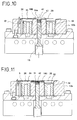
- Fig. 10 is a sectional view of a machine having a resin path in the upper die;
- Fig. 11 is a sectional view of a machine using the additional release film;
- Fig. 12 is a side sectional view of a film forming mechanism;
- Fig. 13 is a front sectional view of the film forming mechanism;
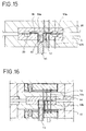
- Fig. 14 is a sectional view of a machine of Third Embodiment;
- Fig. 15 is a sectional view a machine having the resin path in the upper die; and
- Fig. 16 is a sectional view of the conventional resin molding machine.
-
- Fig. 1 is a sectional view of a resin molding machine of the present embodiment, e.g., a machine for molding semiconductor devices. In Fig. 1, the left side of the center line shows a state of clamping a lead frame, which is an example of a member to be molded; the right side of the center line shows a state of filling resin in a
cavity 21. - There are formed cavities in an
upper die 10a and alower die 10b. In the present embodiment, the dies 10a and 10b are made of steel. Butcavity pieces cavity pieces - Fig. 2 shows planar provision of the
cavity pieces 22b on thelower die 10b. In the present embodiment, two lead frames 22 are respectively set on the both sides of apot 12 and molded. - The
cavity pieces cavity pieces plates - Besides the
cavity pieces cull piece 26 are inserted in holes, which are bored in the base sections of theupper die 10a. Thecull piece 26 is arranged to face thepot 12. Thecull piece 26 is also fixed to theplate 24a. Thecull piece 26 also may be made of the metalic material having higher heat conductivity, e.g., copper, aluminum. - As described above, since the
cavity pieces cull piece 26 are made of the metalic material having higher heat conductivity, heat exchange between the resin and the dies is accelerated, so that the resin can be solidified in a short time. By solidifying the resin in a short time, cycle time of the molding work can be shortened. In the present embodiment,heaters cavity pieces cull piece 26 so as to effectively control temperature. - In the present embodiment, faces of the molding dies 10a and 10b are covered with release film. By employing the release film, the metalic materials having higher heat conductivity, e.g., copper, aluminum, which are not used for ordinary molding dies, can be used in the molding dies.
- Faces of the molding dies 10a and 10b, which contact the resin, are previously covered with the release film. The release film preferably has: heat resistibility over the molding temperature of the dies 10a and 10b; peel-ability with respect to the dies 10a and 10b and the resin; and high extensibility. For example, FEP sheet film, PET sheet film, ETFE sheet film, glass cloth in which flouric resin is impregnated, polyvinylidene chloride, etc. can be employed as the release film.
- The present embodiment is characterized in that resin molding sections, e.g., the cavities, the
pot 12 and cull of the dies are covered with a sheet of therelease film 30. - In the resin molding method using the
release film 30, therelease film 30 is fed onto parting faces of the molding dies 10a and 10b, which have been opened, so as to cover the parting faces. Then the resin and members to be molded are set in themolding die 10b. The members to be molded are clamped by the molding dies 10a and 10b and molded by filling the resin in the cavities. - In the present embodiment, the parting faces of the molding dies are covered with the
release film 30, so suckingholes 32, which open in parts of the parting faces: clamping faces, for sucking therelease film 30 are formed. Andcavity sucking holes 36, which are gaps between outer side faces of thecavity pieces cavity pieces release film 30 along inner shapes of the cavities. - As shown in Fig. 2, The sucking
holes 32 are opened in the clamping face and arranged around the cavity. The suckingholes 32 are communicated with air paths in theplates cavity sucking holes 36 are opened like slits and respectively enclose a bottom face of each cavity. Thecavity sucking holes 36 are communicated with air paths in theplates release film 30 is designed to cover over the cavities, which are provided on both sides of thepot 12, in the molding dies 10a and 10b (see Fig. 1). When therelease film 30 is sucked to fix onto the parting faces of the molding dies 10a and 10b, firstly therelease film 30, which has been fed on the parting faces, is sucked by the sucking holes to fix on the clamping faces, then parts of therelease film 30, which cover the cavities, are sucked by thecavity sucking holes 36 to fix the parts of therelease film 30 in the cavities along inner faces thereof. By this sucking process, the cavities, which are covered with therelease film 30, can be formed. - A part of the
release film 30, which covers thepot 12, is sucked by anair path 38, which is a gap between inner faces of thepot 12 and outer side faces of theplunger 13. In the present embodiment, to form theair path 38, aseal ring 39 is attached on the outer faces of theplunger 13 close to a base section of theplunger 13 so as to seal theair path 38, and air paths 40, which connects theair path 38 with thecavity sucking holes 36, are formed in thelower die 10b. Therelease film 30 and the resin melt are pushed up by theplunger 13 while molding, so size of theair path 38 must be designed not to invade therelease film 30 in theair path 38 too much. - With this structure, when the
release film 30 is sucked by thecavity sucking holes 36, therelease film 30 is simultaneously sucked toward thepot 12, so that therelease film 30 can be fixed along the inner faces of thepot 12 and an upper end face of theplunger 13. In the state of opening the dies 10a and 10b, the upper end face of theplunger 13 is located under an opening section of thepot 12 so as to supply the resin tablet into thepot 12, so that a concave section of therelease film 30 is formed in thepot 12 by the air suction. In Fig. 1, the left side of the center line shows the state of fixing therelease film 30 in the cavities and thepot 12; the right side of the center line shows the state of supplying theresin tablet 42 in thepot 12. - The resin tablet used in the present embodiment is generally used in the conventional molding machines, too. The resin tablet is formed by forming crashed tablet into a columnar shape by a compressing machine or by forming a sheet of resin material, which has been extended by an extruding machine, into a tablet shape.
- In the present embodiment, the
pot 12 is a thin and long type pot as shown in Fig. 2 (a plan view), so theresin tablet 42 is formed into a stick shape corresponding to an inner shape of thepot 12. Resin paths andgates 10c, which communicates with the cavities, are branched off from thepot 12. After clamping the lead frames 20, the resin melt is sent by theplunger 13 to mold them. - As shown in the right side of Fig. 1, the
plunger 13 pushes the resin, which has been melt in thepot 12, together with therelease film 30, so that the resin is filled into the cavities via the resin paths and thegates 10c. After completing the mold, molded products are taken out from the molding dies together with therelease film 30. Since therelease film 30 is capable of easily peeling off from the molding dies, the molded products can be easily ejected from the dies without using ejector pins, which must be provided in the conventional molding machines. And therelease film 30 is capable of easily peeling off from the molded products, so thefilm 30 can be easily ejected from the products. After removing therelease film 30, gates of the molded products are removed. Note that, the molded products and therelease film 30 may be assisted to eject from the dies by blowing air, which is sent from the air sucking mechanisms A and B, from the suckingholes - A resin molding machine having a plurality of pots: a multi-pot type machine is shown in Fig. 3. Fig. 3 is a plan view of the
lower die 10b. In this example, the resin paths and thegates 10c are extended from eachpot 12 to the cavities, which are arranged on both sides of a line ofpots 12. Columnar resin tablets are supplied into eachpot 12. - The
release film 30 is sucked to fix on the dies by the manner as well as the above described example. Namely, therelease film 30 is sucked to fix on the clamping faces by the suckingholes 32, then the part of the release film corresponding to the cavities and thepots 12 are sucked to fix in the cavities and the pots along the inner faces thereof. After covering the dies with therelease film 30, the columnar resin tablets are supplied into thepots 12 to mold. - In the present embodiment, by covering the parting faces of the molding dies 10a and 10b with the
release film 30, the molding can be executed without the resin contacting the molding dies. However, the resin sticks onto the lead frames 20 at positions corresponding to the resin paths and thegates 10c, which connect thepot 12 to thecavities 21. To prevent the resin from sticking on the lead frames 20,additional release film 31 is provided between the lead frames 20 and thelower die 10b at the positions corresponding to the resin paths and the pot 12 (see Fig. 4). - The
additional release film 31 is set on thelower die 10b to cover thepot 12, the resin paths and thegates 10c, after fixing therelease film 30 on thelower die 10b and supplying theresin tablets 42 in thepot 12. - After setting the
additional release film 31, the lead frames 20 (the members to be molded) are set and clamped by the molding dies 10a and 10b in which therelease film 30 is fixed. Then molding is executed. In Fig. 4, the right side of the center line shows the state of filling the resin in thecavities 21, no resin is stuck on thelead frame 20 at the position corresponding to the resin path, too by providing theadditional release film 31 between thelead frame 20 and therelease film 30. - Planar arrangement of the
release film 30 and theadditional release film 31 on thelower die 10b is shown in Fig. 5. Theadditional release film 31 is required to cover an upper part of thepot 12, and the resin paths and thegates 10c connecting thepot 12 to the cavities. In the present embodiment, theadditional release film 31 has extendedsections 31b, which is extended from the side edges of theadditional release film 31 to cover connecting sections of thegates 10c and cavity corners. Theextended sections 31b are extended according to the planar arrangement of thepot 12, the resin paths and thegates 10c. To prevent the resin from sticking on the lead frames 20, theadditional release film 31 must be located to correspond to the cavities, thegates 10c, etc.. - In the case of using the
additional release film 31, total film thickness must be thicker, so there must be formed step sections for fitting the thicker film sections in the molding dies. - Note that, the
additional release film 31 is used to prevent the resin from sticking on the lead frames 12, thus theadditional release film 31 may be formed into various shapes other than the shape having theextended sections 31b. - Another example with the
additional release film 31 is shown in Fig. 6. whole one side of thelead frame 20 except positions corresponding to the cavities is covered with theadditional release film 31. Since the cavities of the molding die are covered with therelease film 30, theadditional release film 31 hasholes 30c, which are arranged to correspond to the cavities and whose size is equal to opening sections of the cavities. - In this case, firstly the
release film 30 is fixed on themolding die 10b, theresin tablet 42 is supplied into thepot 12, then theadditional release film 31 is set on thelower die 10b. The additional,release film 31 is wider than therelease film 30 so as to cover whole lead frames 20. To position theadditional release film 31 on thelower die 10b, there are provided guide pins 44 for position the lead frames 20 on thelower die 10b. Fig. 6 shows the state of positioning theadditional release film 31 on thelower die 10b by the guide pins 44 after therelease film 30 is sucked and fixed. By boring positioning holes in theadditional release film 31, theadditional release film 31 can be precisely set on thelower die 10b. Therelease film 30 is, of course, designed not to cover the guide pins 44. - In the case of using the wide
additional release film 31, the lead frames 20 are wholly covered with therelease film 30 and theadditional release film 31, so that the film thickness corresponding to the clamping faces will be equal. Thus, no step sections for fitting the thicker film sections is required in the molding dies. - In the case of using the
additional release film 31 as shown in Figs. 5 and 6, two or more sheets of therelease film 30 may be employed. Two sheets of therelease film 30, for example, may be respectively provided for each lead frames 20, which are set in parallel. - Instead of feeding the
additional release film 31 into the dies, theadditional release film 31 may be previously adhered on thelead frame 20. In this case, theadditional release film 31 is adhered on thelead frame 20 prior to setting thelead frame 20 in the dies. Namely, thelead frame 20 on which theadditional release film 31 has been adhered is set in the dies. - The
resin tablet 42 is supplied into a concave section of therelease film 30, which is formed by sucking therelease film 30 toward inside of thepot 12. But the resin tablet may be set in thepot 12 with the steps of: sucking therelease film 30 to fix on the die by the suckingholes 32 without sucking toward inside of thepot 12; mounting theresin tablet 42 at a position on therelease film 30 corresponding to thepot 12; and lightly closing the dies 10a and 10b once. - After once setting the
resin tablet 42 in thepot 12, the molding dies 10a and 10b are opened. Then therelease film 30 is sucked to fix in the cavities by thecavity sucking holes 36, and the lead frames 20 are set in the dies to mold. Sucking therelease film 30 to fix in the cavities may be executed when therelease film 30 is fixed on the clamping faces prior to setting the resin tablet, - In the method of setting the resin tablet by once closing the dies 10a and 10b lightly, the
release film 30 need not be sucked at thepot 12, strutures of the molding dies can be simpler. - Note that, the above described example shows the machine, which is capable of molding two lead frames in one molding cycle, but the method can be applied to the molding machine, which molds one lead frame in one molding cycle.
- In the above described examples, the
release film 30 is a sheet of film whose all parts are made of same material. The release film, whose specific parts corresponding to the pot and the cavities are made of other film materials, may be employed. In the specific parts, film thickness, etc. may be changed with respect to other parts. In this case, another film may be adhered on the specific parts of a sheet of base film, and another separated film may be provided to the specific parts. - The resin molding machine of the present embodiment has following advantages:
- Since no resin contacts the parting faces of the molding dies, the resin, which is capable of well adhering to the members to be molded, can be used for molding, so that reliability of the molded products can be raised;
- Conventional various kinds of resin tablets, which have been used in the conventional machines, can be used for the machine;
- By exchanging the molding dies and adding the fixing mechanism capable of setting the release film in the dies, the resin molding method using the release film can be executed in the conventional molding machines;
- Since the pot, the cull, runners, the gates and the cavities are wholly covered with the release film, cavity blocks, a center block and the pot, which are separated in the conventional machines, can be formed in one block;
- The molding dies need not be made of hard materials, so they can be made easily; and
- With no ejector pins, heaters with thermosensors can be assembled in the molding dies, so that heat control of the molding dies can be precisely executed.
-
- The molding machine of Second Embodiment employs the a sheet of release film covering over the cavities and the pot as well as the First Embodiment. In the present embodiment, the release film is made of a film material, which previously has a concave section in which the resin tablet can be set.
- Fig. 7 is a plan view of the
lower die 10b on which therelease film 30 and theresin tablet 42 are set. Thecavity sucking holes 36 are opened in eachcavity 5. The suckingholes 32 are opened in the clamping faces of thedie 10b. - The
release film 30 has the width capable of covering thecavities 5 on both sides of thepot 12. - Fig. 8 is a plan view of the
lower die 10b on which therelease film 30 and theresin tablet 42 are set. Thepot 12 is a thin and long type pot, so theresin tablet 42 is formed into a stick shape, which can be set in thelong pot 12. - Fig. 9 is a sectional view of the
lower die 10b on which therelease film 30 and theresin tablet 42 are set. The left side of the center line shows the state of setting therelease film 30 on the die; the right side of the center line shows the state of sucking therelease film 30 to fix on the bottom face of thecavity 5. Theconcave section 30a, which has previously formed in therelease film 30, is fitted in thepot 12, and theresin tablet 42 is set in theconcave section 30a. - In the present embodiment, since the
concave section 30a for accommodating theresin tablet 42 is previously formed in therelease film 30, the step of lightly closing the dies to set the resin tablet in the pot can be omitted. By omitting the film suction in thepot 12, a shift of therelease film 30 can be prevented. - A film forming unit, which forms the
concave section 30a in therelease film 30, is preferably provided prior to the step of feeding therelease film 30 to the molding dies. The film material is pulled out from a film roll, then theconcave section 30a is formed in the film forming unit before feeding to the molding dies. Therelease film 30 is fed to the molding dies by a conveying unit, whose feeding action is synchronized with a series of molding steps. - The film forming unit for forming the
concave section 30a in therelease film 30 is shown in Figs. 12 and 13. Fig. 12 is a side view; Fig. 13 is a front sectional view. The film forming unit has: a die 142 having a die-hole whose shape is equal to the shape of thepot 12; apunch 144, which forms theconcave section 30a with thedie 142; apunch guide 146; and apunch plate 148. Thedie 142 and thepunch 144 are heated byheaters 150. While therelease film 30 is caught by thepunch guide 146 and thedie 142, thepunch 144 and the die 142 press therelease film 30 to form theconcave section 30a in which the resin tablet is set. - The
resin tablet 42 may be supplied with the steps of: forming theconcave section 30a by the film forming unit; feeding therelease film 30 to the molding dies; and supplying theresin tablet 42 into theconcave section 30a of therelease film 30, or may be supplied with the steps of: forming theconcave section 30a by the film forming unit; supplying theresin tablet 42 into theconcave section 30a, which is still in thedie hole 142 of the film forming unit; pre-heating the resin tablet in thedie hole 142; and feeding the resin tablet in the die together with therelease film 30. - In the molding machine shown in Fig. 9, the
resin paths 180 are formed in thelower die 10b; In the molding machine shown in Fig. 10, theresin paths 180 are formed in theupper die 10a. Thus, theresin paths 180, which are the runners, the gates, etc. connecting thepot 12 with the cavities, may be provided not only in thelower die 10b but also in theupper die 10a. - In the state shown in Figs. 9 and 10, the resin will stick on the lead frames 20 at the positions corresponding to the
resin paths 180, which connect thepot 12 with the cavities. Thus, in this case too, theadditional release film 31 can be provided between therelease film 30 and the lead frames 20 as well as the First Embodiment. By using theadditional release film 31, the resin molding can be executed without sticking the resin onto the lead frames 20. The method using theadditional release film 31 is shown in Fig. 11. - The film material having the
extended sections 31b, which have been previously formed, may be fed as theadditional release film 31. Theextended sections 31b may be formed by laser cutting or press cutting before the molding. In the case of supplying theadditional release film 31, which has been formed into a desired shape, e.g., forming theextended sections 31b, theadditional release film 31 is selected on the basis of products. - The formed
additional release film 31 may be adhered to therelease film 30, in which theresin tablet 42 has been already supplied in theconcave section 30a, to tightly wrap therosin tablet 42. In this case, therelease film 30 in which theresin tablet 42 is tightly wrapped will be fed to the molding dies, and the tightly wrappedresin tablet 42 will be set at prescribed position. - The molding machine of Third Embodiment is shown in Fig. 14. In the machine, the molding sections, e.g., the cavities, are not covered with the
release film 30. Therelease film 30 is provided to cover thepot 12 and theresin paths 180, which connect thepot 12 to the lead frames 20. - The
release film 30 has aconcave section 30a into which theresin tablet 42 is supplied as well as the Second Embodiment. - In the present embodiment, since the inner faces of the cavities are not covered with the
release film 30, the resin directly contacts the molding dies, so that the molded products are ejected from the dies by ejectorpins 170, which are provided in the dies. - This method can be applied to the conventional molding machine, which are designed to use no release film. By setting the
release film 30 to cover thepot 12 and theresin paths 180, no resin is stuck onto the inner face of thepot 12, so that the resin solidified in thepot 12 and theresin paths 180 can be easily discharged. - In the example shown in Fig. 14, the
resin paths 180 are formed in thelower die 10b; in an example shown in Fig. 15, theresin paths 180 are formed in theupper die 10a. In the case of forming theresin paths 180 in theupper die 10a, order of setting the lead frames 20 and setting theresin tablet 42 can be changed by providing theresin paths 180 to theupper die 10a or thelower die 10b. In some cases, molding efficiency can be raised by selecting said order. Further, since therelease film 30 is provided on the lead frames 20, the resin can be prevented to directly contact the lead frames 20. - Note that, the
resin tablets 42 in the Second Embodiment and the Third Embodiment are the stick typed resin tablets, but the columnar resin tablets, of course, can be used according to the shape of the pot in the Second Embodiment and the Third Embodiment. - The invention may be embodied in other specific forms without departing from the scope of the claims
Claims (18)
- A method of resin molding,
comprising the steps of:supplying a resin tablet (42) into a pot (12) of molding dies (10a, 10b) each of which includes an associated cavity, andclamping a member (20) to be molded between said molding dies (10a, 10b),
characterised by the step of:covering at least an inner face of said pot (12) and the inner face of the resin path from the pot (12) to the associated cavity with release film (30) which is capable of easily peeling off from said molding dies (10a, 10b) and from the resin. - The method of resin molding according to claim 1,
wherein said covering step comprises the steps of:covering over the face including a cavity, a cull and a pot (12) with a sheet of said release film (30); andsucking said release film (30) to fix onto the face for clamping said member (20) to be molded, an inner face of the cavity, an inner face of the cull and the inner face of the pot (12). - The method of resin molding according to Claim 1,
wherein said covering step comprises the steps of:covering over the face including a cavity, a cull and a pot (12) with a sheet of said release film (30); andsucking said release film (30) to fix onto the face for clamping said member (20) to be molded, an inner face of the cavity and an inner face of the cull; andproviding the resin tablet (42) onto said release film (30) at a position corresponding to the pot (12), and
wherein the resin tablet (42) is set in the pot (12) by closing said molding dies (10a, 10b). - The method of resin molding according to Claim 1,
wherein said release film (30) has an accommodating section into which the resin tablet (42) is supplied, the accommodating section is formed to correspond to an inner shape of the pot (12). - The method of resin molding according to Claim 4,
wherein the accommodating section is formed in said release film (30) before providing said release film (30) on the face of said molding die (10b). - The method of resin molding according to Claim 5,
wherein the resin tablet (42) is preheated in the accommodating section, and
wherein the resin tablet (42) is supplied together with said release film (30). - The method of resin molding according to Claim 1,
wherein a resin path (180), which passes over an opening section of the pot (12) and said member (20) to be molded, is covered with additional release film (31). - The method of resin molding according to Claim 7,
wherein said additional release film (31) is capable of covering over a clamped face of said member (20) to be molded, and
wherein said additional release film (31) has a cavity hole (30c), which is opened to correspond to opening sections of cavities of said molding dies (10a, 10b). - The method of resin molding according to Claim 1,
wherein said supplying step comprises:accommodating the resin tablet (42) in an accommodating section of said release film (30) into which the resin tablet (42) is supplied, the accommodating section is formed to correspond to an inner shape of the pot (12);adhering additional release film (31), which covers over a resin path (180) passing over an opening section of the pot (12) and said member (20) to be molded, on said release film (30) so as to tightly wrap the resin tablet (42); andsetting said release film (30) in which the resin tablet (42) has been tightly wrapped in said molding dies (10a, 10b). - A resin molding machine comprising:molding dies (10a, 10b) capable of clamping a member (20) to be molded; anda pot (12) for sending resin melt to cavities of said molding dies (10a, 10b) with pressure,
and characterised by:a fixing mechanism for fixing a sheet of release film (30), which is capable of easily peeling off from molding dies (10a, 10b) and resin, is provided on faces of molding sections including the cavity, a cull and the pot (12). - The molding machine according to Claim 10,
further comprising an air sucking mechanism, which is provided exterior of said molding dies (10a, 10b),
wherein said fixing mechanism has an air path (38), which is formed between an inner face of the pot (12) and an outer face of a plunger (13) in the pot (12), and the air path (38) is communicated with said air sucking mechanism. - The molding machine according to Claim 11,
further comprising a seal ring (39), which is attached on an outer circumferential face of the plunger (13) and on the base side thereof, said seal ring (39) being capable of air tightly sealing said air path (38) in the midway of the stroke of the plunger (13). - The molding machine according to Claim 11,
further comprising sucking holes (36) for sucking said release film (30) to fix in the cavities, said sucking holes (36) being communicated with the air path (38). - The molding machine according to Claim 10,
wherein said pot (12) is a long pot capable of accommodating the stick-type resin tablet (42). - The molding machine according to Claim 10,
wherein said molding die (10b) has a plurality of pots (12), which are capable of accommodating the columnar resin tablets (42). - A resin molding machine comprising:molding dies (10a,10b), and a pot (12) formed in one of said molding dies (10b),
characterised in that:an inner face of said pot (12) and the inner face of the resin path from the pot (12) to the associated cavity are covered with release film (30) when molding is executed,
and whereina film forming mechanism is provided on a film-supplying side of said molding dies (10a,10b), said film forming mechanism being capable of forming an accommodating section, into which a resin tablet (42) can be located in said release film (30). - The molding machine according to Claim 16,
further comprising a preheating mechanism for preheating the resin tablet (42) which is accommodated in the accommodating section. - The molding machine according to Claim 16,
further comprising an additional release film (31) forming mechanism for forming additional release film (31), which is capable of covering over a resin path (180), which passes over an opening section of the pot (12) and a member (20) to be molded.
Applications Claiming Priority (4)
| Application Number | Priority Date | Filing Date | Title |
|---|---|---|---|
| JP28942894A JP3214789B2 (en) | 1994-11-24 | 1994-11-24 | Resin molding device and resin molding method |
| JP289428/94 | 1994-11-24 | ||
| JP12765895A JP3165350B2 (en) | 1995-05-26 | 1995-05-26 | Resin molding method and resin molding apparatus |
| JP127658/95 | 1995-05-26 |
Publications (3)
| Publication Number | Publication Date |
|---|---|
| EP0719624A2 EP0719624A2 (en) | 1996-07-03 |
| EP0719624A3 EP0719624A3 (en) | 1996-07-24 |
| EP0719624B1 true EP0719624B1 (en) | 1999-04-21 |
Family
ID=26463556
Family Applications (1)
| Application Number | Title | Priority Date | Filing Date |
|---|---|---|---|
| EP95308257A Expired - Lifetime EP0719624B1 (en) | 1994-11-24 | 1995-11-17 | A resin molding machine and a method of resin molding |
Country Status (7)
| Country | Link |
|---|---|
| US (2) | US5800841A (en) |
| EP (1) | EP0719624B1 (en) |
| KR (1) | KR100193591B1 (en) |
| CN (1) | CN1057248C (en) |
| DE (1) | DE69509203T2 (en) |
| MY (1) | MY114536A (en) |
| SG (1) | SG96151A1 (en) |
Families Citing this family (24)
| Publication number | Priority date | Publication date | Assignee | Title |
|---|---|---|---|---|
| US6048483A (en) * | 1996-07-23 | 2000-04-11 | Apic Yamada Corporation | Resin sealing method for chip-size packages |
| JP2970569B2 (en) * | 1997-01-13 | 1999-11-02 | 日本電気株式会社 | Resin sealing method and resin sealing mold device |
| JP3282988B2 (en) * | 1997-05-01 | 2002-05-20 | アピックヤマダ株式会社 | Resin molding method and resin molding apparatus |
| DE19731780A1 (en) * | 1997-07-24 | 1999-01-28 | Inst Mikrotechnik Mainz Gmbh | Sensitive microcomponent manufacture to give flawless surface quality |
| JP3017485B2 (en) * | 1998-01-23 | 2000-03-06 | アピックヤマダ株式会社 | Resin sealing method and resin sealing device for semiconductor device |
| US6117382A (en) | 1998-02-05 | 2000-09-12 | Micron Technology, Inc. | Method for encasing array packages |
| US6632457B1 (en) | 1998-08-14 | 2003-10-14 | Incept Llc | Composite hydrogel drug delivery systems |
| US6409949B1 (en) * | 1999-03-29 | 2002-06-25 | Kabushiki Kaisha Kobe Seiko Sho (Kobe Steel, Ltd.) | Method for thickening a polyester resin |
| JP3510554B2 (en) * | 2000-02-10 | 2004-03-29 | 山形日本電気株式会社 | Resin molding method, mold for molding and wiring substrate |
| US6770236B2 (en) * | 2000-08-22 | 2004-08-03 | Apic Yamada Corp. | Method of resin molding |
| US6700190B2 (en) | 2002-07-26 | 2004-03-02 | Stmicroelectronics, Inc. | Integrated circuit device with exposed upper and lower die surfaces |
| US6785137B2 (en) | 2002-07-26 | 2004-08-31 | Stmicroelectronics, Inc. | Method and system for removing heat from an active area of an integrated circuit device |
| DE20214006U1 (en) * | 2002-09-11 | 2004-02-12 | Marbach Werkzeugbau Gmbh | Thermoforming mold |
| JP2004134591A (en) * | 2002-10-10 | 2004-04-30 | Renesas Technology Corp | Method for manufacturing semiconductor integrated circuit device |
| US7348220B2 (en) * | 2004-04-30 | 2008-03-25 | Sumitomo Bakelite Co., Ltd. | Resin-encapsulated type semiconductor packages, and production method and apparatus therefor |
| US8011917B2 (en) * | 2007-05-09 | 2011-09-06 | Asm Technology Singapore Pte Ltd | Compression molding of an electronic device |
| FR2943268B1 (en) * | 2009-03-20 | 2014-02-28 | Arcil | THERMALLY INSULATING THERMOFROMING MOLD AND ASSOCIATED METHOD. |
| US7943077B2 (en) * | 2009-06-30 | 2011-05-17 | Tyco Healthcare Group Lp | Method for manufacturing a catheter having a separated tip configuration |
| US8439663B2 (en) * | 2011-04-28 | 2013-05-14 | Lockheed Martin Corporation | De-mold liner based injection tool |
| US10226417B2 (en) | 2011-09-16 | 2019-03-12 | Peter Jarrett | Drug delivery systems and applications |
| US9205150B2 (en) | 2011-12-05 | 2015-12-08 | Incept, Llc | Medical organogel processes and compositions |
| CN103465419A (en) * | 2013-09-16 | 2013-12-25 | 铜陵荣鑫机械有限公司 | High-power LED (light-emitting diode) spherical packaging forming machine |
| KR102376487B1 (en) | 2015-02-12 | 2022-03-21 | 삼성전자주식회사 | Manufacturing device of semiconductor package and method for manufacturing the same |
| JP6491508B2 (en) | 2015-03-23 | 2019-03-27 | Towa株式会社 | Resin sealing device and method of manufacturing resin molded product |
Family Cites Families (26)
| Publication number | Priority date | Publication date | Assignee | Title |
|---|---|---|---|---|
| DE1110855B (en) * | 1956-08-13 | 1961-07-13 | Hans Behringer Dr Ing | Drawing tool for foils made of thermoplastic material |
| US3083408A (en) * | 1957-11-21 | 1963-04-02 | Bichl Josef | Machine for injection molding of selfhardening resins |
| US3216060A (en) * | 1960-12-05 | 1965-11-09 | Trojanowski George | Apparatus for the manufacture of molded articles |
| US3410699A (en) * | 1964-10-21 | 1968-11-12 | Peters Leo | Method of and means for embossment and packaging of cold butter |
| US4442056A (en) * | 1980-12-06 | 1984-04-10 | Dusan Slepcevic | Encapsulation mold with gate plate and method of using same |
| US4872825A (en) * | 1984-05-23 | 1989-10-10 | Ross Milton I | Method and apparatus for making encapsulated electronic circuit devices |
| JPS61167515A (en) * | 1985-01-21 | 1986-07-29 | Hitachi Ltd | Mold assembly |
| DE3930414C2 (en) * | 1989-09-12 | 2002-01-10 | Saint Gobain Sekurit D Gmbh | Method and device for producing a glass pane provided for direct gluing to the fastening flange of a window opening |
| JPH01293523A (en) * | 1988-05-20 | 1989-11-27 | Mitsubishi Electric Corp | Seal metal mold for resin-sealed semiconductor device |
| JPH01299008A (en) * | 1988-05-27 | 1989-12-01 | Mitsubishi Electric Corp | Molding device |
| NL8802879A (en) * | 1988-11-22 | 1990-06-18 | Ireneus Johannes Theodorus Mar | METHOD FOR PACKING A CUSTOMIZED QUANTITY OF THERMO-CURING PLASTIC FOR COVERING A COMPONENT, PACKAGING OBTAINED WITH THIS METHOD, METHOD FOR OPERATING A MAT AND DIE FOR CARRYING OUT THIS PROCESS |
| US5000903A (en) * | 1989-04-06 | 1991-03-19 | Libbey-Owens-Ford Co. | Method of molding plastic products having chemically bonded protective coatings |
| US4956141A (en) * | 1989-04-07 | 1990-09-11 | Libbey-Owens-Ford Co. | Molding process utilizing a mold release membrane |
| JPH032911A (en) * | 1989-05-30 | 1991-01-09 | Omron Corp | Buoyancy controller |
| US4965037A (en) * | 1989-07-17 | 1990-10-23 | Libbey-Owens-Ford Co. | Method of molding a composite |
| EP0437345A3 (en) * | 1990-01-10 | 1992-08-19 | Taiyo Manufacturing Works Co., Ltd. | Mold used for fabricating thermoplastic resin articles |
| JPH03234605A (en) * | 1990-02-13 | 1991-10-18 | Toshiba Corp | Resin-molding device |
| JPH0437507A (en) * | 1990-06-02 | 1992-02-07 | Yamada Seisakusho Co Ltd | Mounting structure of ejector pin in molder |
| DE4208642A1 (en) * | 1992-03-18 | 1993-09-23 | Thomae Gmbh Dr K | TOOLS FOR COLD FORMING PLASTIC FILMS, SPECIFICALLY OF POLYPROPYLENE FILMS OF DIFFERENT THICKNESSES |
| JP3138842B2 (en) * | 1992-08-18 | 2001-02-26 | 株式会社ジェルテック | Manufacturing method of silicone gel parts |
| US5529474A (en) * | 1992-09-25 | 1996-06-25 | Texas Instruments Incorporated | System for preheating a molding compound |
| NL9400119A (en) * | 1994-01-27 | 1995-09-01 | 3P Licensing Bv | Method for encapsulating an electronic component with a hardening plastic, electronic components with plastic enclosure obtained by means of this method and mold for carrying out the method. |
| US5674343A (en) * | 1994-04-19 | 1997-10-07 | Nitto Denko Corporation | Method for manufacturing a semiconductor |
| US5542978A (en) * | 1994-06-10 | 1996-08-06 | Johnson & Johnson Vision Products, Inc. | Apparatus for applying a surfactant to mold surfaces |
| US5846477A (en) * | 1994-12-08 | 1998-12-08 | Nitto Denko Corporation | Production method for encapsulating a semiconductor device |
| USH1654H (en) * | 1995-01-10 | 1997-06-03 | Rounds; Nicholas A. | Transfer molding process for encapsulating semiconductor devices |
-
1995
- 1995-11-14 MY MYPI95003451A patent/MY114536A/en unknown
- 1995-11-17 EP EP95308257A patent/EP0719624B1/en not_active Expired - Lifetime
- 1995-11-17 DE DE69509203T patent/DE69509203T2/en not_active Expired - Fee Related
- 1995-11-22 US US08/562,151 patent/US5800841A/en not_active Expired - Lifetime
- 1995-11-23 SG SG9501906A patent/SG96151A1/en unknown
- 1995-11-23 KR KR1019950043096A patent/KR100193591B1/en not_active IP Right Cessation
- 1995-11-24 CN CN95119080A patent/CN1057248C/en not_active Expired - Lifetime
-
1998
- 1998-06-02 US US09/090,153 patent/US6444157B1/en not_active Expired - Lifetime
Also Published As
| Publication number | Publication date |
|---|---|
| DE69509203D1 (en) | 1999-05-27 |
| DE69509203T2 (en) | 1999-10-14 |
| EP0719624A2 (en) | 1996-07-03 |
| US6444157B1 (en) | 2002-09-03 |
| CN1131082A (en) | 1996-09-18 |
| MY114536A (en) | 2002-11-30 |
| EP0719624A3 (en) | 1996-07-24 |
| CN1057248C (en) | 2000-10-11 |
| SG96151A1 (en) | 2003-05-23 |
| US5800841A (en) | 1998-09-01 |
| KR100193591B1 (en) | 1999-06-15 |
| KR960017104A (en) | 1996-06-17 |
Similar Documents
| Publication | Publication Date | Title |
|---|---|---|
| EP0719624B1 (en) | A resin molding machine and a method of resin molding | |
| EP0730937B1 (en) | A resin molding machine with release film | |
| EP0728567B1 (en) | A method and machine for resin molding | |
| KR102175894B1 (en) | extrusion part replacement-type multi-color 3D printer | |
| JP3321023B2 (en) | Resin molding method and resin molding apparatus using liquid resin | |
| JP3709175B2 (en) | Resin sealing molding method for electronic parts | |
| JP2000280295A (en) | Mold for simultaneous molding and decoration and manufacture of article molded and decorated simultaneously | |
| US6682952B2 (en) | Method of forming the resin sealed semiconductor device using the lead frame | |
| JP3214789B2 (en) | Resin molding device and resin molding method | |
| JPH11126787A (en) | Method and mold for resin sealing electronic component | |
| JPH08142105A (en) | Resin molding apparatus using release film | |
| JPH02283414A (en) | Injection molding die and injection molding method using the same | |
| JPH11151733A (en) | Transfer mold apparatus | |
| JP3590133B2 (en) | Resin molding method and resin molding apparatus | |
| JP3909097B2 (en) | Mold structure of resin molding equipment using release film | |
| JP2597010B2 (en) | Mold for mold | |
| JP2736554B2 (en) | Resin sealing molding method and method of forming resin injection gate | |
| JPH0314332Y2 (en) | ||
| JP3826710B2 (en) | Seal molding equipment | |
| JPS6340158Y2 (en) | ||
| JPS58188641A (en) | Multiple extruding device of injection molding machine | |
| JP4247050B2 (en) | Continuous film and in-mold transfer molding method | |
| US6911719B1 (en) | Lead frame for resin sealed semiconductor device | |
| JPH0976283A (en) | Method and apparatus for manufacture of plastic molded produce | |
| JPH05185455A (en) | Mold apparatus for molding resin seal part for electronic part |
Legal Events
| Date | Code | Title | Description |
|---|---|---|---|
| PUAI | Public reference made under article 153(3) epc to a published international application that has entered the european phase |
Free format text: ORIGINAL CODE: 0009012 |
|
| PUAL | Search report despatched |
Free format text: ORIGINAL CODE: 0009013 |
|
| AK | Designated contracting states |
Kind code of ref document: A2 Designated state(s): CH DE GB LI NL |
|
| AK | Designated contracting states |
Kind code of ref document: A3 Designated state(s): CH DE FR GB IE LI NL |
|
| 17P | Request for examination filed |
Effective date: 19961118 |
|
| 17Q | First examination report despatched |
Effective date: 19971127 |
|
| GRAG | Despatch of communication of intention to grant |
Free format text: ORIGINAL CODE: EPIDOS AGRA |
|
| GRAG | Despatch of communication of intention to grant |
Free format text: ORIGINAL CODE: EPIDOS AGRA |
|
| GRAH | Despatch of communication of intention to grant a patent |
Free format text: ORIGINAL CODE: EPIDOS IGRA |
|
| GRAH | Despatch of communication of intention to grant a patent |
Free format text: ORIGINAL CODE: EPIDOS IGRA |
|
| RBV | Designated contracting states (corrected) |
Designated state(s): CH DE GB LI NL |
|
| GRAA | (expected) grant |
Free format text: ORIGINAL CODE: 0009210 |
|
| AK | Designated contracting states |
Kind code of ref document: B1 Designated state(s): CH DE GB LI NL |
|
| REG | Reference to a national code |
Ref country code: CH Ref legal event code: EP |
|
| REF | Corresponds to: |
Ref document number: 69509203 Country of ref document: DE Date of ref document: 19990527 |
|
| REG | Reference to a national code |
Ref country code: CH Ref legal event code: NV Representative=s name: AMMANN PATENTANWAELTE AG BERN |
|
| PLBE | No opposition filed within time limit |
Free format text: ORIGINAL CODE: 0009261 |
|
| STAA | Information on the status of an ep patent application or granted ep patent |
Free format text: STATUS: NO OPPOSITION FILED WITHIN TIME LIMIT |
|
| 26N | No opposition filed | ||
| REG | Reference to a national code |
Ref country code: GB Ref legal event code: IF02 |
|
| PGFP | Annual fee paid to national office [announced via postgrant information from national office to epo] |
Ref country code: DE Payment date: 20071025 Year of fee payment: 13 |
|
| PGFP | Annual fee paid to national office [announced via postgrant information from national office to epo] |
Ref country code: CH Payment date: 20071024 Year of fee payment: 13 |
|
| PGFP | Annual fee paid to national office [announced via postgrant information from national office to epo] |
Ref country code: GB Payment date: 20071019 Year of fee payment: 13 |
|
| REG | Reference to a national code |
Ref country code: CH Ref legal event code: PL |
|
| GBPC | Gb: european patent ceased through non-payment of renewal fee |
Effective date: 20081117 |
|
| PG25 | Lapsed in a contracting state [announced via postgrant information from national office to epo] |
Ref country code: LI Free format text: LAPSE BECAUSE OF NON-PAYMENT OF DUE FEES Effective date: 20081130 Ref country code: DE Free format text: LAPSE BECAUSE OF NON-PAYMENT OF DUE FEES Effective date: 20090603 Ref country code: CH Free format text: LAPSE BECAUSE OF NON-PAYMENT OF DUE FEES Effective date: 20081130 |
|
| PG25 | Lapsed in a contracting state [announced via postgrant information from national office to epo] |
Ref country code: GB Free format text: LAPSE BECAUSE OF NON-PAYMENT OF DUE FEES Effective date: 20081117 |
|
| PGFP | Annual fee paid to national office [announced via postgrant information from national office to epo] |
Ref country code: NL Payment date: 20141126 Year of fee payment: 20 |
|
| REG | Reference to a national code |
Ref country code: NL Ref legal event code: MK Effective date: 20151116 |