EP0718655B1 - Unterstützungsmechanismus für einen Spiegel - Google Patents
Unterstützungsmechanismus für einen Spiegel Download PDFInfo
- Publication number
- EP0718655B1 EP0718655B1 EP95116125A EP95116125A EP0718655B1 EP 0718655 B1 EP0718655 B1 EP 0718655B1 EP 95116125 A EP95116125 A EP 95116125A EP 95116125 A EP95116125 A EP 95116125A EP 0718655 B1 EP0718655 B1 EP 0718655B1
- Authority
- EP
- European Patent Office
- Prior art keywords
- reflector
- socket
- sleeve
- surface part
- supporting mechanism
- Prior art date
- Legal status (The legal status is an assumption and is not a legal conclusion. Google has not performed a legal analysis and makes no representation as to the accuracy of the status listed.)
- Expired - Lifetime
Links
Images


Classifications
-
- G—PHYSICS
- G02—OPTICS
- G02B—OPTICAL ELEMENTS, SYSTEMS OR APPARATUS
- G02B7/00—Mountings, adjusting means, or light-tight connections, for optical elements
- G02B7/18—Mountings, adjusting means, or light-tight connections, for optical elements for prisms; for mirrors
- G02B7/182—Mountings, adjusting means, or light-tight connections, for optical elements for prisms; for mirrors for mirrors
- G02B7/183—Mountings, adjusting means, or light-tight connections, for optical elements for prisms; for mirrors for mirrors specially adapted for very large mirrors, e.g. for astronomy, or solar concentrators
-
- G—PHYSICS
- G02—OPTICS
- G02B—OPTICAL ELEMENTS, SYSTEMS OR APPARATUS
- G02B26/00—Optical devices or arrangements for the control of light using movable or deformable optical elements
- G02B26/06—Optical devices or arrangements for the control of light using movable or deformable optical elements for controlling the phase of light
Definitions
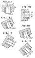
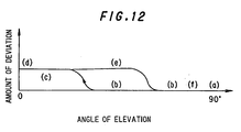
- Fig. 12 (a) to (f) respectively show a status corresponding to the status shown in Figs. 11A to 11F.
Landscapes
- Physics & Mathematics (AREA)
- General Physics & Mathematics (AREA)
- Optics & Photonics (AREA)
- Life Sciences & Earth Sciences (AREA)
- Astronomy & Astrophysics (AREA)
- Sustainable Development (AREA)
- Aerials With Secondary Devices (AREA)
- Telescopes (AREA)
Claims (5)
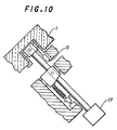
- Reflektorhaltevorrichtung zum Halten eines Reflektors mit einem Gewicht W1, die folgendes umfaßt:wobei ein Bereich einer inneren Seitenfläche der Büchse (2; 2A; 2B; 2C) und ein Bereich einer äußeren Seitenfläche der Hülse (3A; 3; 3B; 3C), der dem Bereich der inneren Seitenfläche gegenüberliegt, als ein konvexes Profil entlang einer Achsenrichtung ausgebildet ist und der andere dieser Seitenflächenbereiche als eine gerade Linie entlang der Achsenrichtung ausgebildet ist, wodurch der Bereich der inneren Seitenfläche der Büchse (2; 2A; 2B; 2C) und der Bereich der äußeren Seitenfläche der Hülse (3A; 3; 3B; 3C) in einem Punktkontakt (3a) zusammenkommen,eine Büchse (2; 2A; 2B; 2C), die in einem auf der Rückfläche eines Reflektors (1) ausgebildeten Loch vorgesehen ist;eine Hülse (3A; 3; 3B; 3C), die entfernbar in die Büchse (2; 2A; 2B; 2C) eingefügt ist;ein Universalgelenk (5), das an der Hülse (3A; 3; 3B; 3C) vorgesehen ist; undeinen Stützhebel (4), der drehbar mit dem Universalgelenk (5) verbunden ist,
dadurch gekennzeichnet, daß
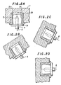
die Position des Bereiches der inneren Seitenfläche der Büchse (2; 2A; 2B; 2C) und des Bereiches der äußeren Seitenfläche der Hülse (3A; 3; 3B; 3C), die in einem Punktkontakt (3a) zusammenkommen, derart bestimmt sind, daß gilt - Reflektorhaltevorrichtung nach Anspruch 1, wobei der Bereich der inneren Seitenfläche der Büchse (2A) derart ausgebildet ist, daß sie im zentralen Bereich konvex ist, und der Bereich der äußeren Seitenfläche der Hülse (3) als eine zylindrische äußere Umfangsfläche ausgebildet ist.
- Reflektorhaltevorrichtung nach Anspruch 1, wobei der Bereich der inneren Seitenfläche der Büchse (2) als eine zylindrische äußere Umfangsfläche ausgebildet ist und der Bereich der Seitenfläche der Hülse (3A) trommelförmmig ist, so daß ihr zentraler Bereich entlang der Achsenrichtung konvex ist.
- Reflektorhaltevorrichtung nach Anspruch 1, wobei der Bereich der inneren Seitenfläche der Büchse (2B) als ein zylindrischer Außenumfang ausgebildet ist, der sich derart verjüngt, daß ein Außendurchmesser eines Endes einer Vorderfläche des Reflektors (1) kleiner als der Außendurchmesser des anderen Endes ist und der Bereich der äußeren Seitenfläche der Hülse (3B) als ein konvexes Profil mit einem Außendurchmesser ausgebildet ist, der von einem Ende der Vorderfläche des Reflektors (1) zu dem anderen Ende entlang einer axialen Richtung größer wird.
- Reflektorhaltevorrichtung nach Anspruch 1, wobei der Bereich der inneren Seitenfläche der Büchse (2C) als ein konvexes Profil mit einem Außendurchmesser ausgebildet ist, der von einem Ende der Vorderfläche des Reflektors (1) zu dem anderen Ende entlang der Achsenrichtung größer wird, und der Bereich der äußeren Seitenfläche der Hülse (3C) als ein zylindrischer Außenumfang ausgebildet ist, der sich verjüngt, so daß ein Außendurchmesser eines Endes der Vorderfläche des Reflektors (1) kleiner als der Außendurchmesser des anderen Endes ist.
Applications Claiming Priority (3)
| Application Number | Priority Date | Filing Date | Title |
|---|---|---|---|
| JP6316681A JP3039607B2 (ja) | 1994-12-20 | 1994-12-20 | 反射鏡支持機構 |
| JP316681/94 | 1994-12-20 | ||
| JP31668194 | 1994-12-20 |
Publications (3)
| Publication Number | Publication Date |
|---|---|
| EP0718655A2 EP0718655A2 (de) | 1996-06-26 |
| EP0718655A3 EP0718655A3 (de) | 1996-12-18 |
| EP0718655B1 true EP0718655B1 (de) | 2002-04-17 |
Family
ID=18079729
Family Applications (1)
| Application Number | Title | Priority Date | Filing Date |
|---|---|---|---|
| EP95116125A Expired - Lifetime EP0718655B1 (de) | 1994-12-20 | 1995-10-12 | Unterstützungsmechanismus für einen Spiegel |
Country Status (4)
| Country | Link |
|---|---|
| US (1) | US5592336A (de) |
| EP (1) | EP0718655B1 (de) |
| JP (1) | JP3039607B2 (de) |
| DE (1) | DE69526416T2 (de) |
Families Citing this family (4)
| Publication number | Priority date | Publication date | Assignee | Title |
|---|---|---|---|---|
| US5831780A (en) * | 1996-01-31 | 1998-11-03 | Raytheon Company | Continually supported thin mirror with force-type actuators |
| WO2006006240A1 (ja) * | 2004-07-14 | 2006-01-19 | Mitsubishi Denki Kabushiki Kaisha | 反射鏡装置 |
| US8860627B2 (en) * | 2007-09-24 | 2014-10-14 | Agence Spatiale Europeenne | Reconfigurable reflector for electromagnetic waves |
| US10727605B2 (en) | 2018-09-05 | 2020-07-28 | Eagle Technology, Llc | High operational frequency fixed mesh antenna reflector |
Family Cites Families (7)
| Publication number | Priority date | Publication date | Assignee | Title |
|---|---|---|---|---|
| US4500170A (en) * | 1982-06-14 | 1985-02-19 | Ford Aerospace & Communications Corporation | Gravity and temperature compensating reflector support actuator |
| US4601723A (en) * | 1985-01-29 | 1986-07-22 | Mcgrew Robert N | Telescoping self-adjusting ossicular prostheses |
| DE3603217A1 (de) * | 1986-01-31 | 1986-09-18 | Christoph Dipl.-Phys. 7928 Giengen Kühne | Halb-monolithisches spiegelteleskop |
| US4845510A (en) * | 1987-08-10 | 1989-07-04 | Hughes Aircraft Company | Reflector surface adjustment structure |
| DE3908430A1 (de) * | 1988-03-18 | 1989-09-28 | Mitsubishi Electric Corp | Spiegelstuetzvorrichtung und spiegelstuetzsystem |
| JP2625547B2 (ja) * | 1989-06-26 | 1997-07-02 | 三菱電機株式会社 | ミラー支持装置 |
| JP2962070B2 (ja) * | 1992-10-02 | 1999-10-12 | 三菱電機株式会社 | 反射鏡支持機構 |
-
1994
- 1994-12-20 JP JP6316681A patent/JP3039607B2/ja not_active Expired - Fee Related
-
1995
- 1995-07-19 US US08/504,137 patent/US5592336A/en not_active Expired - Fee Related
- 1995-10-12 DE DE69526416T patent/DE69526416T2/de not_active Expired - Fee Related
- 1995-10-12 EP EP95116125A patent/EP0718655B1/de not_active Expired - Lifetime
Also Published As
| Publication number | Publication date |
|---|---|
| JP3039607B2 (ja) | 2000-05-08 |
| JPH08171045A (ja) | 1996-07-02 |
| DE69526416T2 (de) | 2002-11-07 |
| DE69526416D1 (de) | 2002-05-23 |
| EP0718655A2 (de) | 1996-06-26 |
| EP0718655A3 (de) | 1996-12-18 |
| US5592336A (en) | 1997-01-07 |
Similar Documents
| Publication | Publication Date | Title |
|---|---|---|
| US6198580B1 (en) | Gimballed optical mount | |
| US20020085291A1 (en) | Mounting device for an optical element | |
| US4763991A (en) | Adjustable six degree of freedom mount for optical components | |
| EP3221733B1 (de) | Sekundärspiegelpositionierungsmechanismus | |
| US5837894A (en) | Wide field of view sensor with diffractive optic corrector | |
| EP0718655B1 (de) | Unterstützungsmechanismus für einen Spiegel | |
| WO2002019007A1 (fr) | Ensemble miroir reflechissant | |
| US7390101B2 (en) | Off-axis two-mirror re-imaging infrared telescope | |
| FR2761286A1 (fr) | Positionneur multiaxe | |
| US5828447A (en) | Orientation location system of an observation instrument | |
| FR2760102A1 (fr) | Autodirecteur orientable | |
| JPH1130709A (ja) | 反射望遠鏡 | |
| EP1767972B1 (de) | Reflexionsspiegelvorrichtung | |
| US8455804B2 (en) | Apparatus for adjusting optical mirrors | |
| CN116841102A (zh) | 一种同质材料大视场相机 | |
| JP3619160B2 (ja) | 反射鏡アンテナ受信位相較正装置 | |
| US5223909A (en) | High frequency reflector alignment method | |
| US20070103771A1 (en) | Two-mirror telescope with central spider support for the secondary mirror | |
| US20260110894A1 (en) | Double lens-barrel device | |
| EP3904000B1 (de) | Blocker mit lichtübertragungs- und -reflexionsvorrichtung | |
| FR3157565A1 (fr) | Télescope Cassegrain à actionneurs piézo-électriques pour viseur gyrostabilisé haute performance | |
| JP7291943B2 (ja) | 経緯台及び望遠鏡システム | |
| CA3113499C (fr) | Procede de mise en poussee sans glissement d'un outil a l'extremite d'un bras articule contre une surface et dispositif pour sa mise en oeuvre | |
| FR2530831A1 (fr) | Dispositif de deviateur optique variable, application a une optique d'autodirecteur | |
| JPH1039233A (ja) | カセグレイン、ニュートン兼用望遠鏡 |
Legal Events
| Date | Code | Title | Description |
|---|---|---|---|
| PUAI | Public reference made under article 153(3) epc to a published international application that has entered the european phase |
Free format text: ORIGINAL CODE: 0009012 |
|
| AK | Designated contracting states |
Kind code of ref document: A2 Designated state(s): DE FR GB |
|
| PUAL | Search report despatched |
Free format text: ORIGINAL CODE: 0009013 |
|
| AK | Designated contracting states |
Kind code of ref document: A3 Designated state(s): DE FR GB |
|
| 17P | Request for examination filed |
Effective date: 19961204 |
|
| 17Q | First examination report despatched |
Effective date: 20001102 |
|
| GRAG | Despatch of communication of intention to grant |
Free format text: ORIGINAL CODE: EPIDOS AGRA |
|
| GRAG | Despatch of communication of intention to grant |
Free format text: ORIGINAL CODE: EPIDOS AGRA |
|
| GRAH | Despatch of communication of intention to grant a patent |
Free format text: ORIGINAL CODE: EPIDOS IGRA |
|
| REG | Reference to a national code |
Ref country code: GB Ref legal event code: IF02 |
|
| GRAH | Despatch of communication of intention to grant a patent |
Free format text: ORIGINAL CODE: EPIDOS IGRA |
|
| GRAH | Despatch of communication of intention to grant a patent |
Free format text: ORIGINAL CODE: EPIDOS IGRA |
|
| GRAA | (expected) grant |
Free format text: ORIGINAL CODE: 0009210 |
|
| AK | Designated contracting states |
Kind code of ref document: B1 Designated state(s): DE FR GB |
|
| REF | Corresponds to: |
Ref document number: 69526416 Country of ref document: DE Date of ref document: 20020523 |
|
| ET | Fr: translation filed | ||
| ET | Fr: translation filed | ||
| PLBE | No opposition filed within time limit |
Free format text: ORIGINAL CODE: 0009261 |
|
| STAA | Information on the status of an ep patent application or granted ep patent |
Free format text: STATUS: NO OPPOSITION FILED WITHIN TIME LIMIT |
|
| 26N | No opposition filed |
Effective date: 20030120 |
|
| PGFP | Annual fee paid to national office [announced via postgrant information from national office to epo] |
Ref country code: DE Payment date: 20061005 Year of fee payment: 12 |
|
| PGFP | Annual fee paid to national office [announced via postgrant information from national office to epo] |
Ref country code: GB Payment date: 20061011 Year of fee payment: 12 |
|
| GBPC | Gb: european patent ceased through non-payment of renewal fee |
Effective date: 20071012 |
|
| PG25 | Lapsed in a contracting state [announced via postgrant information from national office to epo] |
Ref country code: DE Free format text: LAPSE BECAUSE OF NON-PAYMENT OF DUE FEES Effective date: 20080501 |
|
| REG | Reference to a national code |
Ref country code: FR Ref legal event code: ST Effective date: 20080630 |
|
| PGFP | Annual fee paid to national office [announced via postgrant information from national office to epo] |
Ref country code: FR Payment date: 20061010 Year of fee payment: 12 |
|
| PG25 | Lapsed in a contracting state [announced via postgrant information from national office to epo] |
Ref country code: GB Free format text: LAPSE BECAUSE OF NON-PAYMENT OF DUE FEES Effective date: 20071012 |
|
| PG25 | Lapsed in a contracting state [announced via postgrant information from national office to epo] |
Ref country code: FR Free format text: LAPSE BECAUSE OF NON-PAYMENT OF DUE FEES Effective date: 20071031 |