EP0718582B1 - Wärmeaustauscher - Google Patents
Wärmeaustauscher Download PDFInfo
- Publication number
- EP0718582B1 EP0718582B1 EP95402780A EP95402780A EP0718582B1 EP 0718582 B1 EP0718582 B1 EP 0718582B1 EP 95402780 A EP95402780 A EP 95402780A EP 95402780 A EP95402780 A EP 95402780A EP 0718582 B1 EP0718582 B1 EP 0718582B1
- Authority
- EP
- European Patent Office
- Prior art keywords
- face
- heat exchanger
- body portion
- dihedron
- flask
- Prior art date
- Legal status (The legal status is an assumption and is not a legal conclusion. Google has not performed a legal analysis and makes no representation as to the accuracy of the status listed.)
- Expired - Lifetime
Links
Images


Classifications
-
- F—MECHANICAL ENGINEERING; LIGHTING; HEATING; WEAPONS; BLASTING
- F25—REFRIGERATION OR COOLING; COMBINED HEATING AND REFRIGERATION SYSTEMS; HEAT PUMP SYSTEMS; MANUFACTURE OR STORAGE OF ICE; LIQUEFACTION SOLIDIFICATION OF GASES
- F25J—LIQUEFACTION, SOLIDIFICATION OR SEPARATION OF GASES OR GASEOUS OR LIQUEFIED GASEOUS MIXTURES BY PRESSURE AND COLD TREATMENT OR BY BRINGING THEM INTO THE SUPERCRITICAL STATE
- F25J3/00—Processes or apparatus for separating the constituents of gaseous or liquefied gaseous mixtures involving the use of liquefaction or solidification
- F25J3/02—Processes or apparatus for separating the constituents of gaseous or liquefied gaseous mixtures involving the use of liquefaction or solidification by rectification, i.e. by continuous interchange of heat and material between a vapour stream and a liquid stream
- F25J3/04—Processes or apparatus for separating the constituents of gaseous or liquefied gaseous mixtures involving the use of liquefaction or solidification by rectification, i.e. by continuous interchange of heat and material between a vapour stream and a liquid stream for air
- F25J3/04763—Start-up or control of the process; Details of the apparatus used
- F25J3/04866—Construction and layout of air fractionation equipments, e.g. valves, machines
- F25J3/04872—Vertical layout of cold equipments within in the cold box, e.g. columns, heat exchangers etc.
- F25J3/04884—Arrangement of reboiler-condensers
-
- B—PERFORMING OPERATIONS; TRANSPORTING
- B01—PHYSICAL OR CHEMICAL PROCESSES OR APPARATUS IN GENERAL
- B01D—SEPARATION
- B01D1/00—Evaporating
- B01D1/06—Evaporators with vertical tubes
- B01D1/065—Evaporators with vertical tubes by film evaporating
-
- B—PERFORMING OPERATIONS; TRANSPORTING
- B01—PHYSICAL OR CHEMICAL PROCESSES OR APPARATUS IN GENERAL
- B01D—SEPARATION
- B01D1/00—Evaporating
- B01D1/22—Evaporating by bringing a thin layer of the liquid into contact with a heated surface
-
- B—PERFORMING OPERATIONS; TRANSPORTING
- B01—PHYSICAL OR CHEMICAL PROCESSES OR APPARATUS IN GENERAL
- B01D—SEPARATION
- B01D3/00—Distillation or related exchange processes in which liquids are contacted with gaseous media, e.g. stripping
- B01D3/14—Fractional distillation or use of a fractionation or rectification column
- B01D3/32—Other features of fractionating columns ; Constructional details of fractionating columns not provided for in groups B01D3/16 - B01D3/30
- B01D3/322—Reboiler specifications
-
- F—MECHANICAL ENGINEERING; LIGHTING; HEATING; WEAPONS; BLASTING
- F25—REFRIGERATION OR COOLING; COMBINED HEATING AND REFRIGERATION SYSTEMS; HEAT PUMP SYSTEMS; MANUFACTURE OR STORAGE OF ICE; LIQUEFACTION SOLIDIFICATION OF GASES
- F25J—LIQUEFACTION, SOLIDIFICATION OR SEPARATION OF GASES OR GASEOUS OR LIQUEFIED GASEOUS MIXTURES BY PRESSURE AND COLD TREATMENT OR BY BRINGING THEM INTO THE SUPERCRITICAL STATE
- F25J3/00—Processes or apparatus for separating the constituents of gaseous or liquefied gaseous mixtures involving the use of liquefaction or solidification
- F25J3/02—Processes or apparatus for separating the constituents of gaseous or liquefied gaseous mixtures involving the use of liquefaction or solidification by rectification, i.e. by continuous interchange of heat and material between a vapour stream and a liquid stream
- F25J3/04—Processes or apparatus for separating the constituents of gaseous or liquefied gaseous mixtures involving the use of liquefaction or solidification by rectification, i.e. by continuous interchange of heat and material between a vapour stream and a liquid stream for air
- F25J3/04406—Processes or apparatus for separating the constituents of gaseous or liquefied gaseous mixtures involving the use of liquefaction or solidification by rectification, i.e. by continuous interchange of heat and material between a vapour stream and a liquid stream for air using a dual pressure main column system
- F25J3/04412—Processes or apparatus for separating the constituents of gaseous or liquefied gaseous mixtures involving the use of liquefaction or solidification by rectification, i.e. by continuous interchange of heat and material between a vapour stream and a liquid stream for air using a dual pressure main column system in a classical double column flowsheet, i.e. with thermal coupling by a main reboiler-condenser in the bottom of low pressure respectively top of high pressure column
-
- F—MECHANICAL ENGINEERING; LIGHTING; HEATING; WEAPONS; BLASTING
- F25—REFRIGERATION OR COOLING; COMBINED HEATING AND REFRIGERATION SYSTEMS; HEAT PUMP SYSTEMS; MANUFACTURE OR STORAGE OF ICE; LIQUEFACTION SOLIDIFICATION OF GASES
- F25J—LIQUEFACTION, SOLIDIFICATION OR SEPARATION OF GASES OR GASEOUS OR LIQUEFIED GASEOUS MIXTURES BY PRESSURE AND COLD TREATMENT OR BY BRINGING THEM INTO THE SUPERCRITICAL STATE
- F25J5/00—Arrangements of cold exchangers or cold accumulators in separation or liquefaction plants
- F25J5/002—Arrangements of cold exchangers or cold accumulators in separation or liquefaction plants for continuously recuperating cold, i.e. in a so-called recuperative heat exchanger
- F25J5/005—Arrangements of cold exchangers or cold accumulators in separation or liquefaction plants for continuously recuperating cold, i.e. in a so-called recuperative heat exchanger in a reboiler-condenser, e.g. within a column
-
- F—MECHANICAL ENGINEERING; LIGHTING; HEATING; WEAPONS; BLASTING
- F28—HEAT EXCHANGE IN GENERAL
- F28D—HEAT-EXCHANGE APPARATUS, NOT PROVIDED FOR IN ANOTHER SUBCLASS, IN WHICH THE HEAT-EXCHANGE MEDIA DO NOT COME INTO DIRECT CONTACT
- F28D9/00—Heat-exchange apparatus having stationary plate-like or laminated conduit assemblies for both heat-exchange media, the media being in contact with different sides of a conduit wall
- F28D9/0062—Heat-exchange apparatus having stationary plate-like or laminated conduit assemblies for both heat-exchange media, the media being in contact with different sides of a conduit wall the conduits for one heat-exchange medium being formed by spaced plates with inserted elements
- F28D9/0068—Heat-exchange apparatus having stationary plate-like or laminated conduit assemblies for both heat-exchange media, the media being in contact with different sides of a conduit wall the conduits for one heat-exchange medium being formed by spaced plates with inserted elements with means for changing flow direction of one heat exchange medium, e.g. using deflecting zones
-
- F—MECHANICAL ENGINEERING; LIGHTING; HEATING; WEAPONS; BLASTING
- F28—HEAT EXCHANGE IN GENERAL
- F28F—DETAILS OF HEAT-EXCHANGE AND HEAT-TRANSFER APPARATUS, OF GENERAL APPLICATION
- F28F9/00—Casings; Header boxes; Auxiliary supports for elements; Auxiliary members within casings
- F28F9/02—Header boxes; End plates
-
- F—MECHANICAL ENGINEERING; LIGHTING; HEATING; WEAPONS; BLASTING
- F25—REFRIGERATION OR COOLING; COMBINED HEATING AND REFRIGERATION SYSTEMS; HEAT PUMP SYSTEMS; MANUFACTURE OR STORAGE OF ICE; LIQUEFACTION SOLIDIFICATION OF GASES
- F25J—LIQUEFACTION, SOLIDIFICATION OR SEPARATION OF GASES OR GASEOUS OR LIQUEFIED GASEOUS MIXTURES BY PRESSURE AND COLD TREATMENT OR BY BRINGING THEM INTO THE SUPERCRITICAL STATE
- F25J2205/00—Processes or apparatus using other separation and/or other processing means
- F25J2205/02—Processes or apparatus using other separation and/or other processing means using simple phase separation in a vessel or drum
-
- F—MECHANICAL ENGINEERING; LIGHTING; HEATING; WEAPONS; BLASTING
- F25—REFRIGERATION OR COOLING; COMBINED HEATING AND REFRIGERATION SYSTEMS; HEAT PUMP SYSTEMS; MANUFACTURE OR STORAGE OF ICE; LIQUEFACTION SOLIDIFICATION OF GASES
- F25J—LIQUEFACTION, SOLIDIFICATION OR SEPARATION OF GASES OR GASEOUS OR LIQUEFIED GASEOUS MIXTURES BY PRESSURE AND COLD TREATMENT OR BY BRINGING THEM INTO THE SUPERCRITICAL STATE
- F25J2235/00—Processes or apparatus involving steps for increasing the pressure or for conveying of liquid process streams
- F25J2235/50—Processes or apparatus involving steps for increasing the pressure or for conveying of liquid process streams the fluid being oxygen
-
- F—MECHANICAL ENGINEERING; LIGHTING; HEATING; WEAPONS; BLASTING
- F25—REFRIGERATION OR COOLING; COMBINED HEATING AND REFRIGERATION SYSTEMS; HEAT PUMP SYSTEMS; MANUFACTURE OR STORAGE OF ICE; LIQUEFACTION SOLIDIFICATION OF GASES
- F25J—LIQUEFACTION, SOLIDIFICATION OR SEPARATION OF GASES OR GASEOUS OR LIQUEFIED GASEOUS MIXTURES BY PRESSURE AND COLD TREATMENT OR BY BRINGING THEM INTO THE SUPERCRITICAL STATE
- F25J2245/00—Processes or apparatus involving steps for recycling of process streams
- F25J2245/50—Processes or apparatus involving steps for recycling of process streams the recycled stream being oxygen
-
- F—MECHANICAL ENGINEERING; LIGHTING; HEATING; WEAPONS; BLASTING
- F25—REFRIGERATION OR COOLING; COMBINED HEATING AND REFRIGERATION SYSTEMS; HEAT PUMP SYSTEMS; MANUFACTURE OR STORAGE OF ICE; LIQUEFACTION SOLIDIFICATION OF GASES
- F25J—LIQUEFACTION, SOLIDIFICATION OR SEPARATION OF GASES OR GASEOUS OR LIQUEFIED GASEOUS MIXTURES BY PRESSURE AND COLD TREATMENT OR BY BRINGING THEM INTO THE SUPERCRITICAL STATE
- F25J2250/00—Details related to the use of reboiler-condensers
- F25J2250/02—Bath type boiler-condenser using thermo-siphon effect, e.g. with natural or forced circulation or pool boiling, i.e. core-in-kettle heat exchanger
-
- F—MECHANICAL ENGINEERING; LIGHTING; HEATING; WEAPONS; BLASTING
- F25—REFRIGERATION OR COOLING; COMBINED HEATING AND REFRIGERATION SYSTEMS; HEAT PUMP SYSTEMS; MANUFACTURE OR STORAGE OF ICE; LIQUEFACTION SOLIDIFICATION OF GASES
- F25J—LIQUEFACTION, SOLIDIFICATION OR SEPARATION OF GASES OR GASEOUS OR LIQUEFIED GASEOUS MIXTURES BY PRESSURE AND COLD TREATMENT OR BY BRINGING THEM INTO THE SUPERCRITICAL STATE
- F25J2250/00—Details related to the use of reboiler-condensers
- F25J2250/04—Down-flowing type boiler-condenser, i.e. with evaporation of a falling liquid film
-
- F—MECHANICAL ENGINEERING; LIGHTING; HEATING; WEAPONS; BLASTING
- F25—REFRIGERATION OR COOLING; COMBINED HEATING AND REFRIGERATION SYSTEMS; HEAT PUMP SYSTEMS; MANUFACTURE OR STORAGE OF ICE; LIQUEFACTION SOLIDIFICATION OF GASES
- F25J—LIQUEFACTION, SOLIDIFICATION OR SEPARATION OF GASES OR GASEOUS OR LIQUEFIED GASEOUS MIXTURES BY PRESSURE AND COLD TREATMENT OR BY BRINGING THEM INTO THE SUPERCRITICAL STATE
- F25J2250/00—Details related to the use of reboiler-condensers
- F25J2250/30—External or auxiliary boiler-condenser in general, e.g. without a specified fluid or one fluid is not a primary air component or an intermediate fluid
- F25J2250/42—One fluid being nitrogen
-
- F—MECHANICAL ENGINEERING; LIGHTING; HEATING; WEAPONS; BLASTING
- F25—REFRIGERATION OR COOLING; COMBINED HEATING AND REFRIGERATION SYSTEMS; HEAT PUMP SYSTEMS; MANUFACTURE OR STORAGE OF ICE; LIQUEFACTION SOLIDIFICATION OF GASES
- F25J—LIQUEFACTION, SOLIDIFICATION OR SEPARATION OF GASES OR GASEOUS OR LIQUEFIED GASEOUS MIXTURES BY PRESSURE AND COLD TREATMENT OR BY BRINGING THEM INTO THE SUPERCRITICAL STATE
- F25J2250/00—Details related to the use of reboiler-condensers
- F25J2250/30—External or auxiliary boiler-condenser in general, e.g. without a specified fluid or one fluid is not a primary air component or an intermediate fluid
- F25J2250/50—One fluid being oxygen
-
- F—MECHANICAL ENGINEERING; LIGHTING; HEATING; WEAPONS; BLASTING
- F25—REFRIGERATION OR COOLING; COMBINED HEATING AND REFRIGERATION SYSTEMS; HEAT PUMP SYSTEMS; MANUFACTURE OR STORAGE OF ICE; LIQUEFACTION SOLIDIFICATION OF GASES
- F25J—LIQUEFACTION, SOLIDIFICATION OR SEPARATION OF GASES OR GASEOUS OR LIQUEFIED GASEOUS MIXTURES BY PRESSURE AND COLD TREATMENT OR BY BRINGING THEM INTO THE SUPERCRITICAL STATE
- F25J2290/00—Other details not covered by groups F25J2200/00 - F25J2280/00
- F25J2290/32—Details on header or distribution passages of heat exchangers, e.g. of reboiler-condenser or plate heat exchangers
-
- F—MECHANICAL ENGINEERING; LIGHTING; HEATING; WEAPONS; BLASTING
- F28—HEAT EXCHANGE IN GENERAL
- F28D—HEAT-EXCHANGE APPARATUS, NOT PROVIDED FOR IN ANOTHER SUBCLASS, IN WHICH THE HEAT-EXCHANGE MEDIA DO NOT COME INTO DIRECT CONTACT
- F28D21/00—Heat-exchange apparatus not covered by any of the groups F28D1/00 - F28D20/00
- F28D2021/0019—Other heat exchangers for particular applications; Heat exchange systems not otherwise provided for
- F28D2021/0033—Other heat exchangers for particular applications; Heat exchange systems not otherwise provided for for cryogenic applications
-
- Y—GENERAL TAGGING OF NEW TECHNOLOGICAL DEVELOPMENTS; GENERAL TAGGING OF CROSS-SECTIONAL TECHNOLOGIES SPANNING OVER SEVERAL SECTIONS OF THE IPC; TECHNICAL SUBJECTS COVERED BY FORMER USPC CROSS-REFERENCE ART COLLECTIONS [XRACs] AND DIGESTS
- Y10—TECHNICAL SUBJECTS COVERED BY FORMER USPC
- Y10S—TECHNICAL SUBJECTS COVERED BY FORMER USPC CROSS-REFERENCE ART COLLECTIONS [XRACs] AND DIGESTS
- Y10S165/00—Heat exchange
- Y10S165/183—Indirect-contact evaporator
-
- Y—GENERAL TAGGING OF NEW TECHNOLOGICAL DEVELOPMENTS; GENERAL TAGGING OF CROSS-SECTIONAL TECHNOLOGIES SPANNING OVER SEVERAL SECTIONS OF THE IPC; TECHNICAL SUBJECTS COVERED BY FORMER USPC CROSS-REFERENCE ART COLLECTIONS [XRACs] AND DIGESTS
- Y10—TECHNICAL SUBJECTS COVERED BY FORMER USPC
- Y10S—TECHNICAL SUBJECTS COVERED BY FORMER USPC CROSS-REFERENCE ART COLLECTIONS [XRACs] AND DIGESTS
- Y10S165/00—Heat exchange
- Y10S165/911—Vaporization
Definitions
- the present invention relates to a heat exchanger of the type described in the preamble of claim 1.
- Such a heat exchanger is known from DE-A-1 901 475.
- the invention applies in particular to heat exchangers, of the thermosiphon type or of the type with a streaming film, treating at least one two-phase fluid, such as vaporizers-condensers of installations distillation units, group evaporators refrigerators, reboilers of distillation columns, or to certain exchangers arranged in spaces reduced, such as the inter-stage exchangers of some compressors.
- the vaporizers-condensers in question often have to for safety reasons, avoid dry spraying.
- the vaporized product for example oxygen of low pressure column tank of a double column of air distillation, leaves the exchanger in the state two-phase, and must therefore go through a separator of phases which removes droplets from the gas phase and allows the liquid to be recycled.
- the exchanger body generally includes semi-cylindrical fluid inlet / outlet boxes at its two ends, making connection complicated from these boxes to the other components of the compressor and makes the whole device bulky.
- DE-A-1 901 475 describes a heat exchanger of the aforementioned type, which is not suitable for the treatment of fluids under pressure.
- EP-A-0 566 435 very schematically shows a heat exchanger of a neighboring type.
- the object of the invention is to provide a simple construction of heat exchangers of the aforementioned type, capable to effectively withstand fluids under pressure.
- it relates to a heat exchanger of this type, characterized by the characterizing part of claim 1.
- the heat exchanger according to the invention may have one or more of the characteristics described in claims 2 to 7.
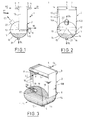
- the heat exchanger 1 shown diagrammatically in Figures 1 to 3 is for example the vaporizer-condenser main of a double distillation column air, of the dripping film type, intended to vaporize partially liquid oxygen under pressure atmospheric by condensing nitrogen under pressure of the order of 5 to 6 bars absolute.
- An example of such vaporizer-condenser is described in EP-A-0 130 122.
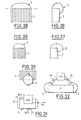
- the exchanger 1 comprises an exchanger body 2 of parallelepiped shape, elongated in the direction vertical, equipped with various accessories.
- treated fluid circulating in the exchanger and undergoing in the body 2 partial condensation or vaporization, that is, in the example considered, liquid oxygen partially vaporized
- these accessories are made by an inlet box 3, connected to a pipe 4 supply of monophasic treated fluid, and a separation flask 5 in its liquid and vapor phases outgoing two-phase fluid.
- a box 6 and a box 7 serving respectively at the inlet and outlet of an auxiliary fluid (in this example nitrogen) and connected respectively to pipes 8 and 9.
- the body 2 is consisting of a stack of rectangular plates 10, vertical and parallel, between which are interposed spacer waves also forming fins thermal.
- Each pair of plates 10 delimits one passage of generally flat shape.
- the passages are closed by bars 11.
- the bars corresponding to the fluid treated however leave free, on one side and above body 2, a row of inlet windows for this fluid, capped by the box 3.
- the bars 11 corresponding at the same fluid are removed on the entire face lower body 2.
- the bars 11 leave a row of entry windows free on the same side as the box 3 but at the bottom of the body 2, these windows being capped by box 6. They leave also free, on the other side and at the top of the body 2, a row of exit windows topped by the box 7.
- the body 2 is produced by stacking plates, spacers and bars, and oven brazing in one single step.
- the input-output boxes 3, 6, 7 have a general semi-cylindrical shape. They are reported on the body 2 by welding, as well as the balloon 5, which will now be described.
- the balloon 5 is produced by welded assembly three cylindrical sheets with a circular base: a part, a central plate 12 whose axis coincides with the horizontal intersection 13 of the underside of the body 2 with the vertical face of this body opposite to boxes 3 and 6, the radius of this sheet being equal to the width L of the plates 10 ( Figure 1).
- each sheet 14 extends, at each level, between its two points of intersection with the central plate 12, which starts from the edge horizontal 15 of body 2 opposite edge 13 and is ends on the opposite vertical face of this body.
- a balloon 5 which has a wide opening in one piece with defined edge as follows: a U-shaped outline that follows three sides consecutive from the base of the body 2, namely the edges bottom of the two end plates 10A, 10B and the edge 15, which consists of edges of the plates and bars 11, and a curvilinear contour which connects to the ends of the U and which consists ( Figure 3) of two arcs 18 connected by a line segment 19.
- the U-shaped contour is welded along the three corresponding edges of body 2, and the curvilinear outline is welded on the adjacent vertical face 20, which consists slices of plates 10 and bars 11.
- the face 20 will be designated by "front face" for simplify the description.
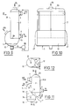
- Figures 11 to 16 show other possible configurations for tank 5, usable with a two-phase fluid at atmospheric pressure or under pressure. All these variants have in common a part 29 in the shape of a half-dome located under the part rear of the body 2, over the entire thickness thereof.
- the sheets side 14 of the half-dome are extended forward, and the balloon comprises a cylinder 30 with vertical axis which intersects the previous one along a curve 31, which is found in a plane P which passes through edge 13 and is tilted down and back at 45 °.
- half of the cylinder 30 is truncated by the body 2.
- the variant of Figure 14 further includes an appendix 14A which goes down from the point bottom of the sheet 14 and which increases the capacity liquid storage tank.
- the sheet metal cylinder 14 is extended into a complete cylinder 36 with horizontal axis beyond face 20, and is closed at the front by a bottom with semi-elliptical section 37.
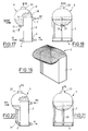
- Figures 17 to 27 show various modes of realization of the invention applied to the case where the two-phase fluid leaves the upper face 38 of the body 2, for example for a main vaporizer-condenser a double air distillation column of the type thermosyphon.
- the balloon covers the all of this face 38 and protrudes on the front face 20 of body 2, so as to present a high point and a low point located respectively above and below of face 38.
- the edge of the balloon is not welded to the end plates 10A, 10B, for the reasons explained above.
- Figures 17 to 19 is obtained by simply reversing that of the Figures 1 to 3. However, it should be noted that in the vaporizers-condensers in question, nitrogen condenses against the flow of oxygen, and therefore in the direction coming down from the exchanger. Figure 19 has been simplified to show only the configuration of the body 2 and ball 5.
- Figure 22 is obtained essentially by reversing that of Figures 11 and 12, the liquid oxygen collected in the lower part of the balloon being returned to a dome lower 40 of the exchanger, welded on the periphery of the lower face of the body 2, via a pipe 41.
- the half-cylinder 30 of the balloon is extended down to cut the extension forward, semi-cylindrical, side plates 41 of the dome 40.
- the intersection 42 found in a plane P tilted forward and down from edge 13. So a single volume of large section completely covers the upper faces, front and lower body 2.
- the transition from the half-cylinder 30 to the half-cylinder 41 can be progressive, for example rounded.
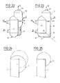
- Figures 24 to 31 illustrate ways whose forms described above can be modified: from the form of Figures 17 to 19, recalled in phantom in Figure 24, you can shift the center of cylinder, side view, down and toward rear (Figure 24), or horizontally and toward the back (Figure 25). These changes allow change the liquid storage capacity and the total size, in each particular application.
- the width of the balloon 5 can be less than the thickness of the body 2 (Figure 30), and / or the ball 5 can protrude both forwards and towards the rear of this body (Figure 31).
- Figure 32 shows how the invention can be used advantageously in contexts other than the treatment of two-phase fluids: a body heat exchanger 2, again of the plate type brazed, is intended to heat or cool a fluid monophasic coming from a device 43, for example from a compressor stage, via line 44 and returning to this device (or another device) via a pipe 45. Thanks to the laterally projecting shape of the balloon 5 provided at each end of the body 2, the connection lines 44 and 45 is greatly facilitated, and the whole has a reduced bulk. This applies well heard in case only one end of body 2 is equipped with a balloon 5.
Landscapes
- Engineering & Computer Science (AREA)
- Physics & Mathematics (AREA)
- Mechanical Engineering (AREA)
- Thermal Sciences (AREA)
- General Engineering & Computer Science (AREA)
- Chemical & Material Sciences (AREA)
- Chemical Kinetics & Catalysis (AREA)
- Separation By Low-Temperature Treatments (AREA)
- Heat-Exchange Devices With Radiators And Conduit Assemblies (AREA)
- Details Of Heat-Exchange And Heat-Transfer (AREA)
- Treating Waste Gases (AREA)
Claims (7)
- Wärmetauscher des Typs, der einerseits versehen ist mit einem Körperteil (2) in Form eines Zweiflachs, der auf einer ersten Fläche des Zweiflachs wenigstens eine Fluideingangs-/Fluidausgangsöffnung aufweist, wobei der Körperteil (2) gebildet ist aus einem Stapel paralleler Platten (10), die zwischen sich flache Durchlässe definieren, aus Wellen-Abstandshaltern, die zwischen diesen Platten angeordnet sind, sowie aus Stäben (11) zum Verschließen der Durchlässe, wobei die Stäbe, die dem Fluid entsprechen, die Öffnung freilassen, und andererseits versehen ist mit einem Eingangs-/Ausgangsbehälter (5) für dieses Fluid, der die Öffnung dicht abdeckt, eine der Kanten des Zweiflachs überspannt und über eine Dichtung mit jeder der Flächen des Zweiflachs, die sich beiderseits der Kante befinden, verbunden ist, dadurch gekennzeichnet, daß der Behälter aus einer Kombination von Blechen (12, 14; 12, 14, 24; 12, 14, 25; 12, 14, 30, 32, 33; 12, 14, 36, 37) in zylindrischer, sphärischer und/oder ellispoidförmiger Form, die miteinander verschweißt sind, verwirklicht ist und mit dem Körperteil (2) nur an denjenigen seiner Flächen verbunden ist, die durch Platten-Stirnscheiben (10) und durch die Stäbe (11) gebildet sind.
- Wärmetauscher nach Anspruch 1, in dem der Körperteil (2) zwischen der ersten Fläche und einer dritten benachbarten Fläche ein zweites Zweiflach bildet dadurch gekennzeichnet, daß der Behälter (5) außerdem in bezug auf den Körperteil über die von ihm überspannte Kante (15) des zweiten Zweiflachs vorsteht.
- Wärmetauscher nach Anspruch 1, dadurch gekennzeichnet, daß der Behälter (5) mit der ersten Fläche längs zweier Linien verbunden ist, die zu der Kante (13, 15) des oder jedes Zweiflachs senkrecht sind, insbesondere längs zweier Ränder dieser Fläche, die zur Kante senkrecht sind.
- Wärmetauscher nach irgendeinem der vorangehenden Ausprüche 1 bis 3, dadurch gekennzeichnet, daß der Behälter aus drei zylindrischen Blechen (12, 14) gebildet ist, wobei die beiden äußeren Bleche (14) Achsen besitzen, die die Achse des mittleren Blechs (12) senkrecht schneiden.
- Wärmetauscher nach irgendeinem der Ansprüche 1 bis 4, der einen Wärmetauscher bildet, dessen Körperteil (2) parallelepipedisch ist, wobei sich die erste Fläche an seinem oberen oder unteren Ende befindet, wobei das Fluid ein zweiphasiges Fluid ist, das diesen Körperteil durch die Öffnung verläßt, dadurch gekennzeichnet, daß der Bebälter (5) einen Flüssigkeitsausgang (21) in der Umgebung seines unteren Punkts und einen Gasausgang (22) in der Umgebung seines oberen Punkts enthält.
- Wärmetauscher nach Anspruch 5, in dem die erste Fläche die obere Fläche des Körperteils ist, dadurch gekennzeichnet, daß der Flüssigkeitsausgang (21) mit einem Flüssigkeitseingang (3) verbunden ist, der sich auf dem untersten Niveau des Körpers (2) befindet.
- Wärmetauscher nach Anspruch 6, dadurch gekennzeichnet, daß der Behälter (5) außerdem die untere Fläche des Körpers (2) abdeckt, die mit dem Flüssigkeitseingang versehen ist.
Applications Claiming Priority (2)
| Application Number | Priority Date | Filing Date | Title |
|---|---|---|---|
| FR9415423 | 1994-12-21 | ||
| FR9415423A FR2728669B1 (fr) | 1994-12-21 | 1994-12-21 | Appareil a circulation de fluide |
Publications (2)
| Publication Number | Publication Date |
|---|---|
| EP0718582A1 EP0718582A1 (de) | 1996-06-26 |
| EP0718582B1 true EP0718582B1 (de) | 1999-10-20 |
Family
ID=9470072
Family Applications (1)
| Application Number | Title | Priority Date | Filing Date |
|---|---|---|---|
| EP95402780A Expired - Lifetime EP0718582B1 (de) | 1994-12-21 | 1995-12-11 | Wärmeaustauscher |
Country Status (9)
| Country | Link |
|---|---|
| US (1) | US5765631A (de) |
| EP (1) | EP0718582B1 (de) |
| JP (2) | JPH08291980A (de) |
| CN (1) | CN1133429A (de) |
| AU (1) | AU703255B2 (de) |
| CA (1) | CA2165719A1 (de) |
| DE (1) | DE69512876T2 (de) |
| FR (1) | FR2728669B1 (de) |
| ZA (1) | ZA9510613B (de) |
Cited By (1)
| Publication number | Priority date | Publication date | Assignee | Title |
|---|---|---|---|---|
| DE102012003417A1 (de) | 2012-02-17 | 2013-08-22 | Uhde Inventa-Fischer Gmbh | Verfahren zur Herstellung eines hochmolekularen, heteroaromatischen Polyesters oder Copolyesters |
Families Citing this family (15)
| Publication number | Priority date | Publication date | Assignee | Title |
|---|---|---|---|---|
| FR2774755B1 (fr) * | 1998-02-09 | 2000-04-28 | Air Liquide | Condenseur a plaques brasees perfectionne et son application aux doubles colonnes de distillation d'air |
| FR2786859B1 (fr) | 1998-12-07 | 2001-01-19 | Air Liquide | Echangeur de chaleur a plaques pour un appareil de separation d'air |
| FR2789165B1 (fr) * | 1999-02-01 | 2001-03-09 | Air Liquide | Echangeur de chaleur, notamment echangeur de chaleur a plaques d'un appareil de separation d'air |
| DE50003157D1 (de) | 1999-03-17 | 2003-09-11 | Linde Ag | Vorrichtung und Verfahren zur Zerlegung eines Gasgemischs bei niedriger Temperatur |
| EP1037004B1 (de) * | 1999-03-17 | 2003-08-06 | Linde Aktiengesellschaft | Vorrichtung und Verfahren zur Zerlegung eines Gasgemischs bei niedriger Temperatur |
| FR2797943A1 (fr) * | 1999-08-24 | 2001-03-02 | Air Liquide | Appareil a circulation de fluide |
| US6349566B1 (en) | 2000-09-15 | 2002-02-26 | Air Products And Chemicals, Inc. | Dephlegmator system and process |
| US6832647B2 (en) * | 2002-04-02 | 2004-12-21 | Modine Manufacturing Company | Integrated condenser/separator for fuel cell exhaust gases |
| US7237406B2 (en) * | 2004-09-07 | 2007-07-03 | Modine Manufacturing Company | Condenser/separator and method |
| CA2623390C (en) * | 2005-09-23 | 2011-08-23 | Heatric | Multiple reactor chemical production system |
| FR2891901B1 (fr) * | 2005-10-06 | 2014-03-14 | Air Liquide | Procede de vaporisation et/ou de condensation dans un echangeur de chaleur |
| US9476609B2 (en) * | 2009-05-06 | 2016-10-25 | Api Heat Transfer Inc. | Water separator and system |
| US8561420B2 (en) * | 2009-05-08 | 2013-10-22 | Honda Motor Co., Ltd. | Evaporator assembly for an HVAC system |
| WO2016146238A1 (de) * | 2015-03-13 | 2016-09-22 | Linde Aktiengesellschaft | Destillationssäulen-system, anlage und verfahren zur erzeugung von sauerstoff durch tieftemperaturzerlegung von luft |
| FR3060553B1 (fr) * | 2016-12-15 | 2021-02-19 | Air Liquide | Echangeur-reacteur comprenant des connecteurs avec supports |
Family Cites Families (9)
| Publication number | Priority date | Publication date | Assignee | Title |
|---|---|---|---|---|
| FR1524343A (fr) * | 1967-03-31 | 1968-05-10 | Air Liquide | Ensemble d'échange indirect de chaleur |
| US3568462A (en) * | 1967-11-22 | 1971-03-09 | Mc Donnell Douglas Corp | Fractionating device |
| US3490522A (en) * | 1968-02-20 | 1970-01-20 | United Aircraft Corp | Heat exchanger pass separator construction |
| DE1901475A1 (de) * | 1969-01-14 | 1970-08-27 | Messer Griesheim Gmbh | Vorrichtung zum Verteilen einer Zweiphasenstroemung auf Plattenwaermeaustauscher |
| JP2531398B2 (ja) * | 1986-10-28 | 1996-09-04 | 石川島播磨重工業株式会社 | プレ−トフィン型熱交換器及びその製造方法 |
| US4773474A (en) * | 1987-08-12 | 1988-09-27 | Modine Manufacturing Company | Snap on fillerneck assembly for radiators |
| FR2665757B1 (fr) * | 1990-08-08 | 1997-01-17 | Valeo Thermique Moteur Sa | Condenseur de fluide refrigerant a circulation verticale, et procede de fabrication. |
| FR2690231B1 (fr) * | 1992-04-17 | 1994-06-03 | Air Liquide | Echangeur de chaleur a ruissellement et installation de distillation d'air comportant un tel echangeur. |
| TW216453B (en) * | 1992-07-08 | 1993-11-21 | Air Prod & Chem | Integrated plate-fin heat exchange reformation |
-
1994
- 1994-12-21 FR FR9415423A patent/FR2728669B1/fr not_active Expired - Fee Related
-
1995
- 1995-12-11 DE DE69512876T patent/DE69512876T2/de not_active Expired - Lifetime
- 1995-12-11 EP EP95402780A patent/EP0718582B1/de not_active Expired - Lifetime
- 1995-12-13 AU AU40403/95A patent/AU703255B2/en not_active Ceased
- 1995-12-13 ZA ZA9510613A patent/ZA9510613B/xx unknown
- 1995-12-20 CA CA002165719A patent/CA2165719A1/en not_active Abandoned
- 1995-12-20 CN CN95120870A patent/CN1133429A/zh active Pending
- 1995-12-20 US US08/575,476 patent/US5765631A/en not_active Expired - Lifetime
- 1995-12-21 JP JP7333470A patent/JPH08291980A/ja active Pending
-
2002
- 2002-12-04 JP JP2002352110A patent/JP3746760B2/ja not_active Expired - Fee Related
Non-Patent Citations (1)
| Title |
|---|
| H. Titze, "Elemente des Apparatebaues", Springer-Verlag, 1963, pages 127 à 129 * |
Cited By (1)
| Publication number | Priority date | Publication date | Assignee | Title |
|---|---|---|---|---|
| DE102012003417A1 (de) | 2012-02-17 | 2013-08-22 | Uhde Inventa-Fischer Gmbh | Verfahren zur Herstellung eines hochmolekularen, heteroaromatischen Polyesters oder Copolyesters |
Also Published As
| Publication number | Publication date |
|---|---|
| JP2003227693A (ja) | 2003-08-15 |
| DE69512876D1 (de) | 1999-11-25 |
| DE69512876T2 (de) | 2000-06-15 |
| CN1133429A (zh) | 1996-10-16 |
| AU703255B2 (en) | 1999-03-25 |
| AU4040395A (en) | 1996-06-27 |
| JPH08291980A (ja) | 1996-11-05 |
| ZA9510613B (en) | 1997-09-15 |
| CA2165719A1 (en) | 1996-06-22 |
| FR2728669A1 (fr) | 1996-06-28 |
| JP3746760B2 (ja) | 2006-02-15 |
| FR2728669B1 (fr) | 1997-04-11 |
| US5765631A (en) | 1998-06-16 |
| EP0718582A1 (de) | 1996-06-26 |
Similar Documents
| Publication | Publication Date | Title |
|---|---|---|
| EP0718582B1 (de) | Wärmeaustauscher | |
| EP0546947B1 (de) | Indirekter Plattenwärmetauscher | |
| WO2007042698A1 (fr) | Procede de vaporisation et/ou de condensation dans un echangeur de chaleur | |
| EP0774102B1 (de) | Verflüssiger mit einbezogenem behälter für klimaanlage eines kraftfahrzeuges | |
| FR2665755A1 (fr) | Appareil de production d'azote. | |
| EP1008826A1 (de) | Fallstrom-Verdampfer und Luftzerlegungsvorrichtung | |
| EP0019508B1 (de) | Thermische Austauschvorrichtung nach Art eines Plattenwärmeaustauschers | |
| FR2718836A1 (fr) | Echangeur de chaleur perfectionné à plaques brasées. | |
| FR3065795B1 (fr) | Echangeur de chaleur a jonction d'ondes amelioree, installation de separation d'air associee et procede de fabrication d'un tel echangeur | |
| EP1179724B1 (de) | Wärmetauscher mit mehrfachen Wärmeaustauschblöcken mit Flüssigkeitsendkammer mit gleichmässiger Verteilung und Verdampfer-Kondensator mit demselben | |
| EP1088578A1 (de) | Verdampfer/Kondensator mit Thermosiphon und entsprechende Luftdestillationsanlage | |
| EP3491326A1 (de) | Vertikaler rohrwärmetauscher und verfahren zum austausch von wärme | |
| EP0738862B1 (de) | Wärmetauscher mit gelöteten Platten | |
| EP0718583B1 (de) | Vorrichtung zur Zirkulation eines Fluids | |
| FR2774755A1 (fr) | Condenseur a plaques brasees perfectionne et son application aux doubles colonnes de distillation d'air | |
| FR2845152A1 (fr) | Echangeur de chaleur a plaques comportant une ailette epaisse, et utilisation d'un tel echangeur de chaleur. | |
| FR2515804A1 (fr) | Echangeur de chaleur, comportant un faisceau de tubes orientes parallelement, pouvant etre sollicite par de l'air | |
| EP1230522B1 (de) | Verdampfer-kondensator und luftzerlegungsanlage | |
| FR2793548A1 (fr) | Vaporiseur-condenseur a plaques fonctionnant en thermosiphon, et double colonne de distillation d'air comportant un tel vaporiseur-condenseur | |
| FR3060729A1 (fr) | Echangeur de chaleur avec dispositif melangeur liquide/gaz a canal isolant thermique | |
| WO2020174173A1 (fr) | Matrice intégrant au moins une fonction d'échange thermique et une fonction de distillation | |
| FR2755220A1 (fr) | Boite collectrice a reservoir integre pour echangeur de chaleur, notamment de vehicule automobile | |
| FR3093170A1 (fr) | Matrice intégrant au moins une fonction d’échange thermique et une fonction de distillation | |
| FR3130952A3 (fr) | Echangeur de chaleur à connectique fluidique améliorée | |
| BE493258A (de) |
Legal Events
| Date | Code | Title | Description |
|---|---|---|---|
| PUAI | Public reference made under article 153(3) epc to a published international application that has entered the european phase |
Free format text: ORIGINAL CODE: 0009012 |
|
| AK | Designated contracting states |
Kind code of ref document: A1 Designated state(s): BE DE ES GB IT NL SE |
|
| 17P | Request for examination filed |
Effective date: 19960507 |
|
| RIN1 | Information on inventor provided before grant (corrected) |
Inventor name: LEHMAN, JEAN-YVES Inventor name: GERARD, CLAUDE |
|
| 17Q | First examination report despatched |
Effective date: 19980206 |
|
| GRAG | Despatch of communication of intention to grant |
Free format text: ORIGINAL CODE: EPIDOS AGRA |
|
| GRAG | Despatch of communication of intention to grant |
Free format text: ORIGINAL CODE: EPIDOS AGRA |
|
| GRAH | Despatch of communication of intention to grant a patent |
Free format text: ORIGINAL CODE: EPIDOS IGRA |
|
| GRAH | Despatch of communication of intention to grant a patent |
Free format text: ORIGINAL CODE: EPIDOS IGRA |
|
| GRAA | (expected) grant |
Free format text: ORIGINAL CODE: 0009210 |
|
| AK | Designated contracting states |
Kind code of ref document: B1 Designated state(s): BE DE ES GB IT NL SE |
|
| PG25 | Lapsed in a contracting state [announced via postgrant information from national office to epo] |
Ref country code: SE Free format text: THE PATENT HAS BEEN ANNULLED BY A DECISION OF A NATIONAL AUTHORITY Effective date: 19991020 Ref country code: IT Free format text: LAPSE BECAUSE OF FAILURE TO SUBMIT A TRANSLATION OF THE DESCRIPTION OR TO PAY THE FEE WITHIN THE PRESCRIBED TIME-LIMIT;WARNING: LAPSES OF ITALIAN PATENTS WITH EFFECTIVE DATE BEFORE 2007 MAY HAVE OCCURRED AT ANY TIME BEFORE 2007. THE CORRECT EFFECTIVE DATE MAY BE DIFFERENT FROM THE ONE RECORDED. Effective date: 19991020 Ref country code: ES Free format text: THE PATENT HAS BEEN ANNULLED BY A DECISION OF A NATIONAL AUTHORITY Effective date: 19991020 |
|
| GBT | Gb: translation of ep patent filed (gb section 77(6)(a)/1977) |
Effective date: 19991028 |
|
| REF | Corresponds to: |
Ref document number: 69512876 Country of ref document: DE Date of ref document: 19991125 |
|
| PG25 | Lapsed in a contracting state [announced via postgrant information from national office to epo] |
Ref country code: BE Free format text: LAPSE BECAUSE OF NON-PAYMENT OF DUE FEES Effective date: 19991231 |
|
| BERE | Be: lapsed |
Owner name: NORDON CRYOGENIE SNC Effective date: 19991231 Owner name: S.A. L' AIR LIQUIDE POUR L'ETUDE ET L'EXPLOITATION Effective date: 19991231 |
|
| PG25 | Lapsed in a contracting state [announced via postgrant information from national office to epo] |
Ref country code: NL Free format text: LAPSE BECAUSE OF NON-PAYMENT OF DUE FEES Effective date: 20000701 |
|
| PLBE | No opposition filed within time limit |
Free format text: ORIGINAL CODE: 0009261 |
|
| STAA | Information on the status of an ep patent application or granted ep patent |
Free format text: STATUS: NO OPPOSITION FILED WITHIN TIME LIMIT |
|
| NLV4 | Nl: lapsed or anulled due to non-payment of the annual fee |
Effective date: 20000701 |
|
| 26N | No opposition filed | ||
| REG | Reference to a national code |
Ref country code: GB Ref legal event code: IF02 |
|
| PGFP | Annual fee paid to national office [announced via postgrant information from national office to epo] |
Ref country code: DE Payment date: 20121207 Year of fee payment: 18 |
|
| PGFP | Annual fee paid to national office [announced via postgrant information from national office to epo] |
Ref country code: GB Payment date: 20121219 Year of fee payment: 18 |
|
| REG | Reference to a national code |
Ref country code: DE Ref legal event code: R119 Ref document number: 69512876 Country of ref document: DE |
|
| GBPC | Gb: european patent ceased through non-payment of renewal fee |
Effective date: 20131211 |
|
| REG | Reference to a national code |
Ref country code: DE Ref legal event code: R119 Ref document number: 69512876 Country of ref document: DE Effective date: 20140701 |
|
| PG25 | Lapsed in a contracting state [announced via postgrant information from national office to epo] |
Ref country code: DE Free format text: LAPSE BECAUSE OF NON-PAYMENT OF DUE FEES Effective date: 20140701 |
|
| PG25 | Lapsed in a contracting state [announced via postgrant information from national office to epo] |
Ref country code: GB Free format text: LAPSE BECAUSE OF NON-PAYMENT OF DUE FEES Effective date: 20131211 |