EP1088578A1 - Verdampfer/Kondensator mit Thermosiphon und entsprechende Luftdestillationsanlage - Google Patents
Verdampfer/Kondensator mit Thermosiphon und entsprechende Luftdestillationsanlage Download PDFInfo
- Publication number
- EP1088578A1 EP1088578A1 EP00402314A EP00402314A EP1088578A1 EP 1088578 A1 EP1088578 A1 EP 1088578A1 EP 00402314 A EP00402314 A EP 00402314A EP 00402314 A EP00402314 A EP 00402314A EP 1088578 A1 EP1088578 A1 EP 1088578A1
- Authority
- EP
- European Patent Office
- Prior art keywords
- section
- fluid
- vaporizer
- passage
- passages
- Prior art date
- Legal status (The legal status is an assumption and is not a legal conclusion. Google has not performed a legal analysis and makes no representation as to the accuracy of the status listed.)
- Withdrawn
Links
Images

Classifications
-
- F—MECHANICAL ENGINEERING; LIGHTING; HEATING; WEAPONS; BLASTING
- F25—REFRIGERATION OR COOLING; COMBINED HEATING AND REFRIGERATION SYSTEMS; HEAT PUMP SYSTEMS; MANUFACTURE OR STORAGE OF ICE; LIQUEFACTION SOLIDIFICATION OF GASES
- F25J—LIQUEFACTION, SOLIDIFICATION OR SEPARATION OF GASES OR GASEOUS OR LIQUEFIED GASEOUS MIXTURES BY PRESSURE AND COLD TREATMENT OR BY BRINGING THEM INTO THE SUPERCRITICAL STATE
- F25J5/00—Arrangements of cold exchangers or cold accumulators in separation or liquefaction plants
- F25J5/002—Arrangements of cold exchangers or cold accumulators in separation or liquefaction plants for continuously recuperating cold, i.e. in a so-called recuperative heat exchanger
- F25J5/007—Arrangements of cold exchangers or cold accumulators in separation or liquefaction plants for continuously recuperating cold, i.e. in a so-called recuperative heat exchanger combined with mass exchange, i.e. in a so-called dephlegmator
-
- B—PERFORMING OPERATIONS; TRANSPORTING
- B01—PHYSICAL OR CHEMICAL PROCESSES OR APPARATUS IN GENERAL
- B01D—SEPARATION
- B01D3/00—Distillation or related exchange processes in which liquids are contacted with gaseous media, e.g. stripping
- B01D3/14—Fractional distillation or use of a fractionation or rectification column
- B01D3/32—Other features of fractionating columns ; Constructional details of fractionating columns not provided for in groups B01D3/16 - B01D3/30
- B01D3/322—Reboiler specifications
-
- F—MECHANICAL ENGINEERING; LIGHTING; HEATING; WEAPONS; BLASTING
- F25—REFRIGERATION OR COOLING; COMBINED HEATING AND REFRIGERATION SYSTEMS; HEAT PUMP SYSTEMS; MANUFACTURE OR STORAGE OF ICE; LIQUEFACTION SOLIDIFICATION OF GASES
- F25J—LIQUEFACTION, SOLIDIFICATION OR SEPARATION OF GASES OR GASEOUS OR LIQUEFIED GASEOUS MIXTURES BY PRESSURE AND COLD TREATMENT OR BY BRINGING THEM INTO THE SUPERCRITICAL STATE
- F25J5/00—Arrangements of cold exchangers or cold accumulators in separation or liquefaction plants
- F25J5/002—Arrangements of cold exchangers or cold accumulators in separation or liquefaction plants for continuously recuperating cold, i.e. in a so-called recuperative heat exchanger
- F25J5/005—Arrangements of cold exchangers or cold accumulators in separation or liquefaction plants for continuously recuperating cold, i.e. in a so-called recuperative heat exchanger in a reboiler-condenser, e.g. within a column
-
- F—MECHANICAL ENGINEERING; LIGHTING; HEATING; WEAPONS; BLASTING
- F28—HEAT EXCHANGE IN GENERAL
- F28D—HEAT-EXCHANGE APPARATUS, NOT PROVIDED FOR IN ANOTHER SUBCLASS, IN WHICH THE HEAT-EXCHANGE MEDIA DO NOT COME INTO DIRECT CONTACT
- F28D9/00—Heat-exchange apparatus having stationary plate-like or laminated conduit assemblies for both heat-exchange media, the media being in contact with different sides of a conduit wall
- F28D9/0062—Heat-exchange apparatus having stationary plate-like or laminated conduit assemblies for both heat-exchange media, the media being in contact with different sides of a conduit wall the conduits for one heat-exchange medium being formed by spaced plates with inserted elements
- F28D9/0068—Heat-exchange apparatus having stationary plate-like or laminated conduit assemblies for both heat-exchange media, the media being in contact with different sides of a conduit wall the conduits for one heat-exchange medium being formed by spaced plates with inserted elements with means for changing flow direction of one heat exchange medium, e.g. using deflecting zones
-
- F—MECHANICAL ENGINEERING; LIGHTING; HEATING; WEAPONS; BLASTING
- F28—HEAT EXCHANGE IN GENERAL
- F28F—DETAILS OF HEAT-EXCHANGE AND HEAT-TRANSFER APPARATUS, OF GENERAL APPLICATION
- F28F3/00—Plate-like or laminated elements; Assemblies of plate-like or laminated elements
- F28F3/02—Elements or assemblies thereof with means for increasing heat-transfer area, e.g. with fins, with recesses, with corrugations
- F28F3/025—Elements or assemblies thereof with means for increasing heat-transfer area, e.g. with fins, with recesses, with corrugations the means being corrugated, plate-like elements
-
- F—MECHANICAL ENGINEERING; LIGHTING; HEATING; WEAPONS; BLASTING
- F25—REFRIGERATION OR COOLING; COMBINED HEATING AND REFRIGERATION SYSTEMS; HEAT PUMP SYSTEMS; MANUFACTURE OR STORAGE OF ICE; LIQUEFACTION SOLIDIFICATION OF GASES
- F25J—LIQUEFACTION, SOLIDIFICATION OR SEPARATION OF GASES OR GASEOUS OR LIQUEFIED GASEOUS MIXTURES BY PRESSURE AND COLD TREATMENT OR BY BRINGING THEM INTO THE SUPERCRITICAL STATE
- F25J2250/00—Details related to the use of reboiler-condensers
- F25J2250/02—Bath type boiler-condenser using thermo-siphon effect, e.g. with natural or forced circulation or pool boiling, i.e. core-in-kettle heat exchanger
-
- F—MECHANICAL ENGINEERING; LIGHTING; HEATING; WEAPONS; BLASTING
- F25—REFRIGERATION OR COOLING; COMBINED HEATING AND REFRIGERATION SYSTEMS; HEAT PUMP SYSTEMS; MANUFACTURE OR STORAGE OF ICE; LIQUEFACTION SOLIDIFICATION OF GASES
- F25J—LIQUEFACTION, SOLIDIFICATION OR SEPARATION OF GASES OR GASEOUS OR LIQUEFIED GASEOUS MIXTURES BY PRESSURE AND COLD TREATMENT OR BY BRINGING THEM INTO THE SUPERCRITICAL STATE
- F25J2290/00—Other details not covered by groups F25J2200/00 - F25J2280/00
- F25J2290/32—Details on header or distribution passages of heat exchangers, e.g. of reboiler-condenser or plate heat exchangers
-
- F—MECHANICAL ENGINEERING; LIGHTING; HEATING; WEAPONS; BLASTING
- F28—HEAT EXCHANGE IN GENERAL
- F28F—DETAILS OF HEAT-EXCHANGE AND HEAT-TRANSFER APPARATUS, OF GENERAL APPLICATION
- F28F2250/00—Arrangements for modifying the flow of the heat exchange media, e.g. flow guiding means; Particular flow patterns
- F28F2250/10—Particular pattern of flow of the heat exchange media
- F28F2250/102—Particular pattern of flow of the heat exchange media with change of flow direction
Definitions
- the present invention relates to a vaporizer-condenser with thermosyphon, of the type comprising a stack parallel plates, closing bars and spacer waves, which define a first series of passages for a source-supplied spray fluid, and a second series of passages for at least one fluid heater.
- the invention applies in particular to main vaporizers-condensers of air distillation, which vaporizes liquid oxygen under low pressure (typically slightly higher than the atmospheric pressure) by medium nitrogen condensation pressure (typically 5 to 6 bar absolute), and it will be explained below in this app.
- the invention aims to obtain an exchange significant thermal between the two fluids thanks to a rate high liquid recirculation, i.e. with a relatively low liquid flow resistance.
- the invention relates to a vaporizer-condenser of the aforementioned type, characterized in that the passages of the first series of passage have a section variable and have a section over their length passage which increases from bottom to top.
- the invention also relates to an installation air distillation apparatus comprising a distillation apparatus of air fitted with a vaporizer-condenser to vaporize liquid oxygen under low pressure by condensation of nitrogen under medium pressure, this vaporizer-condenser being as defined above.
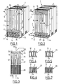
- FIGS. 1 and 2 show a vaporizer-condenser 1 of a double air distillation column not shown, intended to vaporize liquid oxygen in the tank of the low pressure column by condensation of nitrogen gas head of the medium pressure column. It is a vaporizer-condenser of the “bath” or “to” type thermosiphon ".
- the vaporizer-condenser 1 comprises a body single exchanger 2 of generally parallelepiped shape.
- This body consists of a stack of plates vertical rectangles 3, all identical, of bars of peripheral closure 4 and of wave-spacers, by example in perforated corrugated iron, described below. The whole is brazed in the oven in a single operation.
- So body 2 are welded two boxes of generally semi-cylindrical shape, namely an upper side box 5 nitrogen gas inlet and a lower side box 6 liquid nitrogen outlet.
- Each pair of adjacent plates 3 delimits a passage of generally flat shape. These passages are alternately oxygen passages 7 (Figure 1) and nitrogen passages 8 ( Figure 2). Bars 4 close the around these passages, with the exception of openings inlet / outlet for fluids.
- the passages 7 are closed laterally on their full height, except for a side window lower 9 opposite the box 6. They are totally open up and completely closed down.
- the passages 8 are closed over their entire periphery except for an upper side window 10 nitrogen gas inlet, which leads to the box 5, and a lower side window 11 for nitrogen outlet liquid, on which the box opens 6.
- each passage 7 contains a spacer wave 12 with vertical generators.
- it contains a succession of waves which form, possibly with two transverse separating bars partial as illustrated, a zigzag path from window 9: an input wave 13 with generators horizontal, a first triangular return wave 14 to vertical generators, and a return wave 15 to horizontal generators.
- the latter leads to a second triangular return wave 16 with generators vertical, which itself leads to an oblique wave 17 which redistributes the fluid over the entire width of the wave 12.
- Each passage 8 ( Figure 2) contains at its top an oblique wave 18 adapted to distribute the nitrogen gas which enters through the box 5 over the entire width of a wave main 19 with vertical generators. Below this this is an oblique collector wave 20 which collects essentially liquid nitrogen on a wave triangular 21 of return to vertical generators. This in turn leads to an evacuation wave 22 liquid nitrogen with horizontal generators, which ends on window 11. Again, as illustrated, a partial crossbar can be provided between the waves 20 and 22.
- the vaporizer-condenser In operation, the vaporizer-condenser is almost completely submerged in the collected liquid oxygen at the bottom of the low pressure column. Liquid oxygen is simultaneously introduced into all passages 7 via the windows 9, i.e. it supplies these passages with source. Due to the hydrostatic height of the bath, the liquid oxygen is then sub-cooled. He travels horizontally wave 13 then wave 15, following two paths of small flow section forming a zigzag. he begins to vaporize in wave 15, so that its density decreases. It is then distributed by wave 17 in wave 12, which gives the ascending two-phase fluid a significantly larger flow section.
- the passage section increases when the mass volume of the fluid increases. This leads to a easier flow, and therefore better recirculation oxygen.
- the heat exchange coefficient on the side oxygen which depends on the speed of circulation, is thus improved.
- the two-phase oxygen comes out at the top of the passages 7.
- the gaseous oxygen rises in the low pressure column, while excess liquid oxygen falls back into the bath liquid oxygen by overflow, as indicated by arrows in Figure 1.
- wave 18 first flows along wave 19, with a section significant flow. Then, when a fraction substantial nitrogen is condensed, nitrogen is gathered by wave 20 in wave 22, which gives it a significantly reduced flow section. Wave 22 gives the nitrogen path a configuration adapted to that of the path of oxygen in the area, opposite, of wave 13.
- the "incondensables” (hydrogen, helium and neon) are evacuated from the double column via a pipe 23 stitched at the top of the box 6.
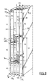
- each oxygen passage 7 contains a full wave 12 generators vertical.
- wave 12 has a variable pitch, moreover wider from bottom to top, and / or consists of a increasingly thin sheet from bottom to top, this so gradually increase the cross section of oxygen.
- the spaces 24 delimited by the undulations are free in the upper section 25 of the passage, while in sections 26 to 28 located below, they are progressively more and more obstructed by inserts.
- the inserts are thin-walled U-shaped sheets 29.
- these are thick-walled U-shaped sheets 30.
- these are solid bars 31 connected to a support rod 32 in the manner of a comb, each rod 32 applying to the lower end edge of the corresponding wave 12, leaving a fraction free important of the entry section of passage 7 as we see in Figure 7A.
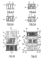
- the vaporizer-condenser of Figure 8 works with an upward circulation of nitrogen gas and descending from liquid nitrogen, i.e. dephlegmator.
- the oxygen passages are fully open down.
- the nitrogen gas enters the nitrogen passages through a lower side entry box 105, which also serves evacuation of liquid nitrogen, and the incondensables are evacuated via an upper outlet box 106.
- the oxygen flow section is doubled on the height of the intermediate sections, then increased by 50% on the height of the upper sections.
- the nitrogen passage section is reduced by a third over the height of the intermediate sections, then divided by two on that of the upper sections.
- the 4BC and 4 CD bars have advantageously oblique upper and lower edges, which give them a parallelogram section. Moreover, we can provide very perforated spacers in the spaces 33 and 34.
- the 4BC and 4 CD bars in Figure 8 are replaced by pairs of spaced bars, with between they a free space 35 connected to a setting device depression (not shown).
- Figures 10 to 12 works on the same principle as that of Figure 9, except know with a passing section gradually increasing from bottom to top for oxygen and a section of progressively decreasing passage from bottom to top for nitrogen.
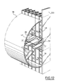
- Figures 10 and 11 the diagram is similar to that in Figure 3. The difference is the fact that the three heat exchange sections are produced respectively in three exchanger bodies different 2A, 2B and 2C, with connections between respective passages of these exchanger bodies.
- end plates 103 are common to three exchanger bodies, and vertical plates transverse 36 provide a tight connection between these two plates, the upper edge of the lower heat exchanger body and the lower edge of the upper body (only the contours such a plate have been shown in Figure 12, to clarify more).
- These plates 36 can be flat as shown in Figure 12, or possibly curved outward as shown in Figures 10 and 11 for better resist the pressure of nitrogen.
- each space 37 four side boxes 38 are provided which overlap both the top 39 nitrogen outlet windows gaseous from the lower body and the lower windows 40 nitrogen gas inlet and liquid nitrogen outlet from upper body.
- each box 38 are provided on the one hand an upper deflector 41 which descends from the edge lower of the upper body, and on the other hand a deflector lower 42 which rises from the wall of the box 38 and is staggered under the deflector 41.
- This baffle arrangement ensures evacuation partial liquid nitrogen at two intermediate levels vaporizer-condenser, as well as an unhindered rise nitrogen gas from one body to another.
Landscapes
- Engineering & Computer Science (AREA)
- Physics & Mathematics (AREA)
- Mechanical Engineering (AREA)
- Thermal Sciences (AREA)
- General Engineering & Computer Science (AREA)
- Chemical & Material Sciences (AREA)
- Chemical Kinetics & Catalysis (AREA)
- Separation By Low-Temperature Treatments (AREA)
- Heat-Exchange Devices With Radiators And Conduit Assemblies (AREA)
Applications Claiming Priority (2)
| Application Number | Priority Date | Filing Date | Title |
|---|---|---|---|
| FR9911778 | 1999-09-21 | ||
| FR9911778A FR2798599B1 (fr) | 1999-09-21 | 1999-09-21 | Vaporiseur-condenseur a thermosiphon et installation de distillation d'air correspondante |
Publications (1)
| Publication Number | Publication Date |
|---|---|
| EP1088578A1 true EP1088578A1 (de) | 2001-04-04 |
Family
ID=9550072
Family Applications (1)
| Application Number | Title | Priority Date | Filing Date |
|---|---|---|---|
| EP00402314A Withdrawn EP1088578A1 (de) | 1999-09-21 | 2000-08-18 | Verdampfer/Kondensator mit Thermosiphon und entsprechende Luftdestillationsanlage |
Country Status (3)
| Country | Link |
|---|---|
| EP (1) | EP1088578A1 (de) |
| JP (1) | JP2001133173A (de) |
| FR (1) | FR2798599B1 (de) |
Cited By (10)
| Publication number | Priority date | Publication date | Assignee | Title |
|---|---|---|---|---|
| FR2865027A1 (fr) * | 2004-01-12 | 2005-07-15 | Air Liquide | Ailette pour echangeur de chaleur et echangeur de chaleur muni de telles ailettes |
| FR2967762A1 (fr) * | 2010-11-24 | 2012-05-25 | Air Liquide | Procede de circulation d'un fluide de conditionnement dans un echangeur de chaleur, d'analyse d'un tel fluide et echangeur de chaleur |
| CN102654375A (zh) * | 2012-04-20 | 2012-09-05 | 苏州制氧机有限责任公司 | 一种主换热器中板翅式热交换器空气抽口装置 |
| US20150361922A1 (en) * | 2014-06-13 | 2015-12-17 | Honeywell International Inc. | Heat exchanger designs using variable geometries and configurations |
| CN105758236A (zh) * | 2016-03-03 | 2016-07-13 | 中持水务股份有限公司 | 一种污泥换热器 |
| WO2021019160A1 (fr) * | 2019-08-01 | 2021-02-04 | L'air Liquide Societe Anonyme Pour L'etude Et L'exploitation Des Procedes Georges Claude | Échangeur de chaleur avec configuration de passages et structures d'échange thermique ameliorées et procédé de refroidissement en utilisant au moins un tel échangeur |
| WO2021019153A1 (fr) * | 2019-08-01 | 2021-02-04 | L'air Liquide Societe Anonyme Pour L'etude Et L'exploitation Des Procedes Georges Claude | Procédé de liquéfaction de gaz naturel avec circulation améliorée d'un courant réfrigérant mixte |
| EP3524913B1 (de) | 2016-10-07 | 2022-04-06 | Sumitomo Precision Products Co., Ltd. | Wärmetauscher |
| US12085334B2 (en) | 2019-08-01 | 2024-09-10 | L'air Liquide, Societe Anonyme Pour L'etude Et L'exploitation Des Procedes Georges Claude | Method for liquefying natural gas with improved injection of a mixed refrigerant stream |
| WO2024183948A1 (de) * | 2023-03-08 | 2024-09-12 | Linde Gmbh | Wärmetauscher sowie zugehörige anlagen und verfahren |
Families Citing this family (6)
| Publication number | Priority date | Publication date | Assignee | Title |
|---|---|---|---|---|
| PL1890100T3 (pl) * | 2006-08-08 | 2018-11-30 | Linde Ag | Skraplacz zwrotny |
| EP1890099A1 (de) * | 2006-08-08 | 2008-02-20 | Linde Aktiengesellschaft | Rücklaufkondensator |
| DE102009050482B4 (de) * | 2009-10-23 | 2011-09-01 | Voith Patent Gmbh | Wärmeübertragerplatte und Verdampfer mit einer solchen |
| KR101534497B1 (ko) * | 2013-10-17 | 2015-07-09 | 한국원자력연구원 | 증기발생기용 열교환기 및 이를 구비하는 증기발생기 |
| KR101565436B1 (ko) | 2014-09-22 | 2015-11-03 | 한국원자력연구원 | 열교환기 및 이를 구비하는 원전 |
| KR102586353B1 (ko) * | 2021-04-08 | 2023-10-19 | 고려대학교 산학협력단 | 배플형 판형 열교환기 및 이를 포함하는 유기랭킨사이클 증발기 |
Citations (6)
| Publication number | Priority date | Publication date | Assignee | Title |
|---|---|---|---|---|
| US4599097A (en) * | 1983-06-24 | 1986-07-08 | L'air Liquide, Societe Anonyme Pour L'etude Et L'exploitation Des Procedes George Claude | Process and device for vaporizing a liquid by heat exchange with a second fluid and their application in an air distillation installation |
| US4715433A (en) * | 1986-06-09 | 1987-12-29 | Air Products And Chemicals, Inc. | Reboiler-condenser with doubly-enhanced plates |
| EP0501471A2 (de) * | 1991-03-01 | 1992-09-02 | Air Products And Chemicals, Inc. | Siedeverfahren und Wärmetauscher zur Verwendung in diesem Verfahren |
| US5333683A (en) * | 1991-12-11 | 1994-08-02 | L'air Liquide, Societe Anonyme Pour L'etude Et L'exploitation Des Procedes Georges Claude | Indirect heat exchanger |
| EP0740119A2 (de) * | 1995-04-28 | 1996-10-30 | Air Products And Chemicals, Inc. | Vorrichtungen zum Abtauen und Verteilen von Flüssigkeiten in Wärmetaucher mit von Rippen versehenen Platten |
| US5724834A (en) * | 1994-08-05 | 1998-03-10 | Praxair Technology, Inc. | Downflow plate and fin heat exchanger for cryogenic rectification |
-
1999
- 1999-09-21 FR FR9911778A patent/FR2798599B1/fr not_active Expired - Fee Related
-
2000
- 2000-08-18 EP EP00402314A patent/EP1088578A1/de not_active Withdrawn
- 2000-09-20 JP JP2000284456A patent/JP2001133173A/ja active Pending
Patent Citations (6)
| Publication number | Priority date | Publication date | Assignee | Title |
|---|---|---|---|---|
| US4599097A (en) * | 1983-06-24 | 1986-07-08 | L'air Liquide, Societe Anonyme Pour L'etude Et L'exploitation Des Procedes George Claude | Process and device for vaporizing a liquid by heat exchange with a second fluid and their application in an air distillation installation |
| US4715433A (en) * | 1986-06-09 | 1987-12-29 | Air Products And Chemicals, Inc. | Reboiler-condenser with doubly-enhanced plates |
| EP0501471A2 (de) * | 1991-03-01 | 1992-09-02 | Air Products And Chemicals, Inc. | Siedeverfahren und Wärmetauscher zur Verwendung in diesem Verfahren |
| US5333683A (en) * | 1991-12-11 | 1994-08-02 | L'air Liquide, Societe Anonyme Pour L'etude Et L'exploitation Des Procedes Georges Claude | Indirect heat exchanger |
| US5724834A (en) * | 1994-08-05 | 1998-03-10 | Praxair Technology, Inc. | Downflow plate and fin heat exchanger for cryogenic rectification |
| EP0740119A2 (de) * | 1995-04-28 | 1996-10-30 | Air Products And Chemicals, Inc. | Vorrichtungen zum Abtauen und Verteilen von Flüssigkeiten in Wärmetaucher mit von Rippen versehenen Platten |
Cited By (16)
| Publication number | Priority date | Publication date | Assignee | Title |
|---|---|---|---|---|
| FR2865027A1 (fr) * | 2004-01-12 | 2005-07-15 | Air Liquide | Ailette pour echangeur de chaleur et echangeur de chaleur muni de telles ailettes |
| WO2005075920A2 (fr) * | 2004-01-12 | 2005-08-18 | L'air Liquide Societe Anonyme A Directoire Et Conseil De Surveillance Pour L'etude Et L'exploitation Des Procedes Georges Claude | Ailette pour échangeur de chaleur et échangeur de chaleur muni de telles ailettes |
| WO2005075920A3 (fr) * | 2004-01-12 | 2005-10-13 | Air Liquide | Ailette pour échangeur de chaleur et échangeur de chaleur muni de telles ailettes |
| JP2007520682A (ja) * | 2004-01-12 | 2007-07-26 | レール・リキード−ソシエテ・アノニム・ア・ディレクトワール・エ・コンセイユ・ドゥ・スールベイランス・プール・レテュード・エ・レクスプロワタシオン・デ・プロセデ・ジョルジュ・クロード | 熱交換器のためのフィンと複数のこのようなフィンを備えた熱交換器 |
| FR2967762A1 (fr) * | 2010-11-24 | 2012-05-25 | Air Liquide | Procede de circulation d'un fluide de conditionnement dans un echangeur de chaleur, d'analyse d'un tel fluide et echangeur de chaleur |
| CN102654375A (zh) * | 2012-04-20 | 2012-09-05 | 苏州制氧机有限责任公司 | 一种主换热器中板翅式热交换器空气抽口装置 |
| US10222142B2 (en) | 2014-06-13 | 2019-03-05 | Honeywell International Inc. | Heat exchanger designs using variable geometries and configurations |
| US20150361922A1 (en) * | 2014-06-13 | 2015-12-17 | Honeywell International Inc. | Heat exchanger designs using variable geometries and configurations |
| CN105758236A (zh) * | 2016-03-03 | 2016-07-13 | 中持水务股份有限公司 | 一种污泥换热器 |
| EP3524913B1 (de) | 2016-10-07 | 2022-04-06 | Sumitomo Precision Products Co., Ltd. | Wärmetauscher |
| WO2021019160A1 (fr) * | 2019-08-01 | 2021-02-04 | L'air Liquide Societe Anonyme Pour L'etude Et L'exploitation Des Procedes Georges Claude | Échangeur de chaleur avec configuration de passages et structures d'échange thermique ameliorées et procédé de refroidissement en utilisant au moins un tel échangeur |
| WO2021019153A1 (fr) * | 2019-08-01 | 2021-02-04 | L'air Liquide Societe Anonyme Pour L'etude Et L'exploitation Des Procedes Georges Claude | Procédé de liquéfaction de gaz naturel avec circulation améliorée d'un courant réfrigérant mixte |
| FR3099557A1 (fr) * | 2019-08-01 | 2021-02-05 | L'air Liquide, Societe Anonyme Pour L'etude Et L'exploitation Des Procedes Georges Claude | Procédé de liquéfaction de gaz naturel avec circulation améliorée d’un courant réfrigérant mixte |
| FR3099563A1 (fr) * | 2019-08-01 | 2021-02-05 | L'air Liquide, Societe Anonyme Pour L'etude Et L'exploitation Des Procedes Georges Claude | Echangeur de chaleur avec configuration de passages et structures d’échange thermique améliorées |
| US12085334B2 (en) | 2019-08-01 | 2024-09-10 | L'air Liquide, Societe Anonyme Pour L'etude Et L'exploitation Des Procedes Georges Claude | Method for liquefying natural gas with improved injection of a mixed refrigerant stream |
| WO2024183948A1 (de) * | 2023-03-08 | 2024-09-12 | Linde Gmbh | Wärmetauscher sowie zugehörige anlagen und verfahren |
Also Published As
| Publication number | Publication date |
|---|---|
| JP2001133173A (ja) | 2001-05-18 |
| FR2798599A1 (fr) | 2001-03-23 |
| FR2798599B1 (fr) | 2001-11-09 |
Similar Documents
| Publication | Publication Date | Title |
|---|---|---|
| EP1088578A1 (de) | Verdampfer/Kondensator mit Thermosiphon und entsprechende Luftdestillationsanlage | |
| EP0546947B1 (de) | Indirekter Plattenwärmetauscher | |
| EP0130122B1 (de) | Apparat zum Verdampfen einer Flüssigkeit durch Wärmeaustausch mit einem zweiten Fluid und Luftdestillationsanlage mit einem solchen Apparat | |
| EP0566435B1 (de) | Rieselwärmetauscher und Lufttrennungseinrichtung mit einem solchen Wärmetauscher | |
| CA2048432A1 (fr) | Appareil de production d'azote | |
| EP1709380A1 (de) | Wärmetauscher und entsprechendes austauschmodul | |
| FR2718836A1 (fr) | Echangeur de chaleur perfectionné à plaques brasées. | |
| EP3479044A1 (de) | Wärmetauscher mit einer vorrichtung zur verteilung eines flüssigkeits-gas-gemisches | |
| FR2571837A1 (fr) | Appareil de rechauffage de fluide | |
| EP1179724B1 (de) | Wärmetauscher mit mehrfachen Wärmeaustauschblöcken mit Flüssigkeitsendkammer mit gleichmässiger Verteilung und Verdampfer-Kondensator mit demselben | |
| EP1730461A2 (de) | Rippe für wärmetauscher und mit solchen rippen ausgestatteter wärmetauscher | |
| EP0738862A1 (de) | Wärmetauscher mit gelöteten Platten und entsprechendes Verfahren zur Behandlung einer zweiphasigen Flüssigkeit | |
| FR2774755A1 (fr) | Condenseur a plaques brasees perfectionne et son application aux doubles colonnes de distillation d'air | |
| FR2798598A1 (fr) | Vaporiseur-condenseur a bain et appareil de distillation d'air correspondant | |
| EP1067344B1 (de) | Verdampferkondensor mit hartgelöteten Platten und deren Verwendung in einer Luftdestillationsvorrichtung | |
| FR2674947A1 (fr) | Procede de vaporisation d'un liquide, echangeur de chaleur pour sa mise en óoeuvre, et application a une installation de distillation d'air a double colonne. | |
| FR2793548A1 (fr) | Vaporiseur-condenseur a plaques fonctionnant en thermosiphon, et double colonne de distillation d'air comportant un tel vaporiseur-condenseur | |
| WO2001014808A1 (fr) | Vaporiseur-condenseur et installation de distillation d'air correspondante | |
| EP0553340B1 (de) | Plattenwärmetauscher | |
| FR2797943A1 (fr) | Appareil a circulation de fluide | |
| EP0864834B1 (de) | Wärmetauscher mit dichter Wirbelschicht kombiniert mit einem Reaktor mit zirkulierender Wirbelschicht | |
| LU81954A1 (fr) | Appareil pour le dessalement de l'eau de mer | |
| FR2761147A1 (fr) | Echangeur de chaleur a encombrement reduit | |
| FR2738499A1 (fr) | Appareil de cristallisation | |
| FR3132851A3 (fr) | Appareil de distillation |
Legal Events
| Date | Code | Title | Description |
|---|---|---|---|
| PUAI | Public reference made under article 153(3) epc to a published international application that has entered the european phase |
Free format text: ORIGINAL CODE: 0009012 |
|
| AK | Designated contracting states |
Kind code of ref document: A1 Designated state(s): DE FR GB |
|
| AX | Request for extension of the european patent |
Free format text: AL;LT;LV;MK;RO;SI |
|
| 17P | Request for examination filed |
Effective date: 20011004 |
|
| AKX | Designation fees paid |
Free format text: DE FR GB |
|
| RAP1 | Party data changed (applicant data changed or rights of an application transferred) |
Owner name: L'AIR LIQUIDE, S.A. A DIRECTOIRE ET CONSEIL DE SUR |
|
| STAA | Information on the status of an ep patent application or granted ep patent |
Free format text: STATUS: THE APPLICATION IS DEEMED TO BE WITHDRAWN |
|
| 18D | Application deemed to be withdrawn |
Effective date: 20050301 |