EP0718582B1 - Heatexchanger - Google Patents
Heatexchanger Download PDFInfo
- Publication number
- EP0718582B1 EP0718582B1 EP95402780A EP95402780A EP0718582B1 EP 0718582 B1 EP0718582 B1 EP 0718582B1 EP 95402780 A EP95402780 A EP 95402780A EP 95402780 A EP95402780 A EP 95402780A EP 0718582 B1 EP0718582 B1 EP 0718582B1
- Authority
- EP
- European Patent Office
- Prior art keywords
- face
- heat exchanger
- body portion
- dihedron
- flask
- Prior art date
- Legal status (The legal status is an assumption and is not a legal conclusion. Google has not performed a legal analysis and makes no representation as to the accuracy of the status listed.)
- Expired - Lifetime
Links
Images


Classifications
-
- F—MECHANICAL ENGINEERING; LIGHTING; HEATING; WEAPONS; BLASTING
- F25—REFRIGERATION OR COOLING; COMBINED HEATING AND REFRIGERATION SYSTEMS; HEAT PUMP SYSTEMS; MANUFACTURE OR STORAGE OF ICE; LIQUEFACTION SOLIDIFICATION OF GASES
- F25J—LIQUEFACTION, SOLIDIFICATION OR SEPARATION OF GASES OR GASEOUS OR LIQUEFIED GASEOUS MIXTURES BY PRESSURE AND COLD TREATMENT OR BY BRINGING THEM INTO THE SUPERCRITICAL STATE
- F25J3/00—Processes or apparatus for separating the constituents of gaseous or liquefied gaseous mixtures involving the use of liquefaction or solidification
- F25J3/02—Processes or apparatus for separating the constituents of gaseous or liquefied gaseous mixtures involving the use of liquefaction or solidification by rectification, i.e. by continuous interchange of heat and material between a vapour stream and a liquid stream
- F25J3/04—Processes or apparatus for separating the constituents of gaseous or liquefied gaseous mixtures involving the use of liquefaction or solidification by rectification, i.e. by continuous interchange of heat and material between a vapour stream and a liquid stream for air
- F25J3/04763—Start-up or control of the process; Details of the apparatus used
- F25J3/04866—Construction and layout of air fractionation equipments, e.g. valves, machines
- F25J3/04872—Vertical layout of cold equipments within in the cold box, e.g. columns, heat exchangers etc.
- F25J3/04884—Arrangement of reboiler-condensers
-
- B—PERFORMING OPERATIONS; TRANSPORTING
- B01—PHYSICAL OR CHEMICAL PROCESSES OR APPARATUS IN GENERAL
- B01D—SEPARATION
- B01D1/00—Evaporating
- B01D1/06—Evaporators with vertical tubes
- B01D1/065—Evaporators with vertical tubes by film evaporating
-
- B—PERFORMING OPERATIONS; TRANSPORTING
- B01—PHYSICAL OR CHEMICAL PROCESSES OR APPARATUS IN GENERAL
- B01D—SEPARATION
- B01D1/00—Evaporating
- B01D1/22—Evaporating by bringing a thin layer of the liquid into contact with a heated surface
-
- B—PERFORMING OPERATIONS; TRANSPORTING
- B01—PHYSICAL OR CHEMICAL PROCESSES OR APPARATUS IN GENERAL
- B01D—SEPARATION
- B01D3/00—Distillation or related exchange processes in which liquids are contacted with gaseous media, e.g. stripping
- B01D3/14—Fractional distillation or use of a fractionation or rectification column
- B01D3/32—Other features of fractionating columns ; Constructional details of fractionating columns not provided for in groups B01D3/16 - B01D3/30
- B01D3/322—Reboiler specifications
-
- F—MECHANICAL ENGINEERING; LIGHTING; HEATING; WEAPONS; BLASTING
- F25—REFRIGERATION OR COOLING; COMBINED HEATING AND REFRIGERATION SYSTEMS; HEAT PUMP SYSTEMS; MANUFACTURE OR STORAGE OF ICE; LIQUEFACTION SOLIDIFICATION OF GASES
- F25J—LIQUEFACTION, SOLIDIFICATION OR SEPARATION OF GASES OR GASEOUS OR LIQUEFIED GASEOUS MIXTURES BY PRESSURE AND COLD TREATMENT OR BY BRINGING THEM INTO THE SUPERCRITICAL STATE
- F25J3/00—Processes or apparatus for separating the constituents of gaseous or liquefied gaseous mixtures involving the use of liquefaction or solidification
- F25J3/02—Processes or apparatus for separating the constituents of gaseous or liquefied gaseous mixtures involving the use of liquefaction or solidification by rectification, i.e. by continuous interchange of heat and material between a vapour stream and a liquid stream
- F25J3/04—Processes or apparatus for separating the constituents of gaseous or liquefied gaseous mixtures involving the use of liquefaction or solidification by rectification, i.e. by continuous interchange of heat and material between a vapour stream and a liquid stream for air
- F25J3/04406—Processes or apparatus for separating the constituents of gaseous or liquefied gaseous mixtures involving the use of liquefaction or solidification by rectification, i.e. by continuous interchange of heat and material between a vapour stream and a liquid stream for air using a dual pressure main column system
- F25J3/04412—Processes or apparatus for separating the constituents of gaseous or liquefied gaseous mixtures involving the use of liquefaction or solidification by rectification, i.e. by continuous interchange of heat and material between a vapour stream and a liquid stream for air using a dual pressure main column system in a classical double column flowsheet, i.e. with thermal coupling by a main reboiler-condenser in the bottom of low pressure respectively top of high pressure column
-
- F—MECHANICAL ENGINEERING; LIGHTING; HEATING; WEAPONS; BLASTING
- F25—REFRIGERATION OR COOLING; COMBINED HEATING AND REFRIGERATION SYSTEMS; HEAT PUMP SYSTEMS; MANUFACTURE OR STORAGE OF ICE; LIQUEFACTION SOLIDIFICATION OF GASES
- F25J—LIQUEFACTION, SOLIDIFICATION OR SEPARATION OF GASES OR GASEOUS OR LIQUEFIED GASEOUS MIXTURES BY PRESSURE AND COLD TREATMENT OR BY BRINGING THEM INTO THE SUPERCRITICAL STATE
- F25J5/00—Arrangements of cold exchangers or cold accumulators in separation or liquefaction plants
- F25J5/002—Arrangements of cold exchangers or cold accumulators in separation or liquefaction plants for continuously recuperating cold, i.e. in a so-called recuperative heat exchanger
- F25J5/005—Arrangements of cold exchangers or cold accumulators in separation or liquefaction plants for continuously recuperating cold, i.e. in a so-called recuperative heat exchanger in a reboiler-condenser, e.g. within a column
-
- F—MECHANICAL ENGINEERING; LIGHTING; HEATING; WEAPONS; BLASTING
- F28—HEAT EXCHANGE IN GENERAL
- F28D—HEAT-EXCHANGE APPARATUS, NOT PROVIDED FOR IN ANOTHER SUBCLASS, IN WHICH THE HEAT-EXCHANGE MEDIA DO NOT COME INTO DIRECT CONTACT
- F28D9/00—Heat-exchange apparatus having stationary plate-like or laminated conduit assemblies for both heat-exchange media, the media being in contact with different sides of a conduit wall
- F28D9/0062—Heat-exchange apparatus having stationary plate-like or laminated conduit assemblies for both heat-exchange media, the media being in contact with different sides of a conduit wall the conduits for one heat-exchange medium being formed by spaced plates with inserted elements
- F28D9/0068—Heat-exchange apparatus having stationary plate-like or laminated conduit assemblies for both heat-exchange media, the media being in contact with different sides of a conduit wall the conduits for one heat-exchange medium being formed by spaced plates with inserted elements with means for changing flow direction of one heat exchange medium, e.g. using deflecting zones
-
- F—MECHANICAL ENGINEERING; LIGHTING; HEATING; WEAPONS; BLASTING
- F28—HEAT EXCHANGE IN GENERAL
- F28F—DETAILS OF HEAT-EXCHANGE AND HEAT-TRANSFER APPARATUS, OF GENERAL APPLICATION
- F28F9/00—Casings; Header boxes; Auxiliary supports for elements; Auxiliary members within casings
- F28F9/02—Header boxes; End plates
-
- F—MECHANICAL ENGINEERING; LIGHTING; HEATING; WEAPONS; BLASTING
- F25—REFRIGERATION OR COOLING; COMBINED HEATING AND REFRIGERATION SYSTEMS; HEAT PUMP SYSTEMS; MANUFACTURE OR STORAGE OF ICE; LIQUEFACTION SOLIDIFICATION OF GASES
- F25J—LIQUEFACTION, SOLIDIFICATION OR SEPARATION OF GASES OR GASEOUS OR LIQUEFIED GASEOUS MIXTURES BY PRESSURE AND COLD TREATMENT OR BY BRINGING THEM INTO THE SUPERCRITICAL STATE
- F25J2205/00—Processes or apparatus using other separation and/or other processing means
- F25J2205/02—Processes or apparatus using other separation and/or other processing means using simple phase separation in a vessel or drum
-
- F—MECHANICAL ENGINEERING; LIGHTING; HEATING; WEAPONS; BLASTING
- F25—REFRIGERATION OR COOLING; COMBINED HEATING AND REFRIGERATION SYSTEMS; HEAT PUMP SYSTEMS; MANUFACTURE OR STORAGE OF ICE; LIQUEFACTION SOLIDIFICATION OF GASES
- F25J—LIQUEFACTION, SOLIDIFICATION OR SEPARATION OF GASES OR GASEOUS OR LIQUEFIED GASEOUS MIXTURES BY PRESSURE AND COLD TREATMENT OR BY BRINGING THEM INTO THE SUPERCRITICAL STATE
- F25J2235/00—Processes or apparatus involving steps for increasing the pressure or for conveying of liquid process streams
- F25J2235/50—Processes or apparatus involving steps for increasing the pressure or for conveying of liquid process streams the fluid being oxygen
-
- F—MECHANICAL ENGINEERING; LIGHTING; HEATING; WEAPONS; BLASTING
- F25—REFRIGERATION OR COOLING; COMBINED HEATING AND REFRIGERATION SYSTEMS; HEAT PUMP SYSTEMS; MANUFACTURE OR STORAGE OF ICE; LIQUEFACTION SOLIDIFICATION OF GASES
- F25J—LIQUEFACTION, SOLIDIFICATION OR SEPARATION OF GASES OR GASEOUS OR LIQUEFIED GASEOUS MIXTURES BY PRESSURE AND COLD TREATMENT OR BY BRINGING THEM INTO THE SUPERCRITICAL STATE
- F25J2245/00—Processes or apparatus involving steps for recycling of process streams
- F25J2245/50—Processes or apparatus involving steps for recycling of process streams the recycled stream being oxygen
-
- F—MECHANICAL ENGINEERING; LIGHTING; HEATING; WEAPONS; BLASTING
- F25—REFRIGERATION OR COOLING; COMBINED HEATING AND REFRIGERATION SYSTEMS; HEAT PUMP SYSTEMS; MANUFACTURE OR STORAGE OF ICE; LIQUEFACTION SOLIDIFICATION OF GASES
- F25J—LIQUEFACTION, SOLIDIFICATION OR SEPARATION OF GASES OR GASEOUS OR LIQUEFIED GASEOUS MIXTURES BY PRESSURE AND COLD TREATMENT OR BY BRINGING THEM INTO THE SUPERCRITICAL STATE
- F25J2250/00—Details related to the use of reboiler-condensers
- F25J2250/02—Bath type boiler-condenser using thermo-siphon effect, e.g. with natural or forced circulation or pool boiling, i.e. core-in-kettle heat exchanger
-
- F—MECHANICAL ENGINEERING; LIGHTING; HEATING; WEAPONS; BLASTING
- F25—REFRIGERATION OR COOLING; COMBINED HEATING AND REFRIGERATION SYSTEMS; HEAT PUMP SYSTEMS; MANUFACTURE OR STORAGE OF ICE; LIQUEFACTION SOLIDIFICATION OF GASES
- F25J—LIQUEFACTION, SOLIDIFICATION OR SEPARATION OF GASES OR GASEOUS OR LIQUEFIED GASEOUS MIXTURES BY PRESSURE AND COLD TREATMENT OR BY BRINGING THEM INTO THE SUPERCRITICAL STATE
- F25J2250/00—Details related to the use of reboiler-condensers
- F25J2250/04—Down-flowing type boiler-condenser, i.e. with evaporation of a falling liquid film
-
- F—MECHANICAL ENGINEERING; LIGHTING; HEATING; WEAPONS; BLASTING
- F25—REFRIGERATION OR COOLING; COMBINED HEATING AND REFRIGERATION SYSTEMS; HEAT PUMP SYSTEMS; MANUFACTURE OR STORAGE OF ICE; LIQUEFACTION SOLIDIFICATION OF GASES
- F25J—LIQUEFACTION, SOLIDIFICATION OR SEPARATION OF GASES OR GASEOUS OR LIQUEFIED GASEOUS MIXTURES BY PRESSURE AND COLD TREATMENT OR BY BRINGING THEM INTO THE SUPERCRITICAL STATE
- F25J2250/00—Details related to the use of reboiler-condensers
- F25J2250/30—External or auxiliary boiler-condenser in general, e.g. without a specified fluid or one fluid is not a primary air component or an intermediate fluid
- F25J2250/42—One fluid being nitrogen
-
- F—MECHANICAL ENGINEERING; LIGHTING; HEATING; WEAPONS; BLASTING
- F25—REFRIGERATION OR COOLING; COMBINED HEATING AND REFRIGERATION SYSTEMS; HEAT PUMP SYSTEMS; MANUFACTURE OR STORAGE OF ICE; LIQUEFACTION SOLIDIFICATION OF GASES
- F25J—LIQUEFACTION, SOLIDIFICATION OR SEPARATION OF GASES OR GASEOUS OR LIQUEFIED GASEOUS MIXTURES BY PRESSURE AND COLD TREATMENT OR BY BRINGING THEM INTO THE SUPERCRITICAL STATE
- F25J2250/00—Details related to the use of reboiler-condensers
- F25J2250/30—External or auxiliary boiler-condenser in general, e.g. without a specified fluid or one fluid is not a primary air component or an intermediate fluid
- F25J2250/50—One fluid being oxygen
-
- F—MECHANICAL ENGINEERING; LIGHTING; HEATING; WEAPONS; BLASTING
- F25—REFRIGERATION OR COOLING; COMBINED HEATING AND REFRIGERATION SYSTEMS; HEAT PUMP SYSTEMS; MANUFACTURE OR STORAGE OF ICE; LIQUEFACTION SOLIDIFICATION OF GASES
- F25J—LIQUEFACTION, SOLIDIFICATION OR SEPARATION OF GASES OR GASEOUS OR LIQUEFIED GASEOUS MIXTURES BY PRESSURE AND COLD TREATMENT OR BY BRINGING THEM INTO THE SUPERCRITICAL STATE
- F25J2290/00—Other details not covered by groups F25J2200/00 - F25J2280/00
- F25J2290/32—Details on header or distribution passages of heat exchangers, e.g. of reboiler-condenser or plate heat exchangers
-
- F—MECHANICAL ENGINEERING; LIGHTING; HEATING; WEAPONS; BLASTING
- F28—HEAT EXCHANGE IN GENERAL
- F28D—HEAT-EXCHANGE APPARATUS, NOT PROVIDED FOR IN ANOTHER SUBCLASS, IN WHICH THE HEAT-EXCHANGE MEDIA DO NOT COME INTO DIRECT CONTACT
- F28D21/00—Heat-exchange apparatus not covered by any of the groups F28D1/00 - F28D20/00
- F28D2021/0019—Other heat exchangers for particular applications; Heat exchange systems not otherwise provided for
- F28D2021/0033—Other heat exchangers for particular applications; Heat exchange systems not otherwise provided for for cryogenic applications
-
- Y—GENERAL TAGGING OF NEW TECHNOLOGICAL DEVELOPMENTS; GENERAL TAGGING OF CROSS-SECTIONAL TECHNOLOGIES SPANNING OVER SEVERAL SECTIONS OF THE IPC; TECHNICAL SUBJECTS COVERED BY FORMER USPC CROSS-REFERENCE ART COLLECTIONS [XRACs] AND DIGESTS
- Y10—TECHNICAL SUBJECTS COVERED BY FORMER USPC
- Y10S—TECHNICAL SUBJECTS COVERED BY FORMER USPC CROSS-REFERENCE ART COLLECTIONS [XRACs] AND DIGESTS
- Y10S165/00—Heat exchange
- Y10S165/183—Indirect-contact evaporator
-
- Y—GENERAL TAGGING OF NEW TECHNOLOGICAL DEVELOPMENTS; GENERAL TAGGING OF CROSS-SECTIONAL TECHNOLOGIES SPANNING OVER SEVERAL SECTIONS OF THE IPC; TECHNICAL SUBJECTS COVERED BY FORMER USPC CROSS-REFERENCE ART COLLECTIONS [XRACs] AND DIGESTS
- Y10—TECHNICAL SUBJECTS COVERED BY FORMER USPC
- Y10S—TECHNICAL SUBJECTS COVERED BY FORMER USPC CROSS-REFERENCE ART COLLECTIONS [XRACs] AND DIGESTS
- Y10S165/00—Heat exchange
- Y10S165/911—Vaporization
Definitions
- the present invention relates to a heat exchanger of the type described in the preamble of claim 1.
- Such a heat exchanger is known from DE-A-1 901 475.
- the invention applies in particular to heat exchangers, of the thermosiphon type or of the type with a streaming film, treating at least one two-phase fluid, such as vaporizers-condensers of installations distillation units, group evaporators refrigerators, reboilers of distillation columns, or to certain exchangers arranged in spaces reduced, such as the inter-stage exchangers of some compressors.
- the vaporizers-condensers in question often have to for safety reasons, avoid dry spraying.
- the vaporized product for example oxygen of low pressure column tank of a double column of air distillation, leaves the exchanger in the state two-phase, and must therefore go through a separator of phases which removes droplets from the gas phase and allows the liquid to be recycled.
- the exchanger body generally includes semi-cylindrical fluid inlet / outlet boxes at its two ends, making connection complicated from these boxes to the other components of the compressor and makes the whole device bulky.
- DE-A-1 901 475 describes a heat exchanger of the aforementioned type, which is not suitable for the treatment of fluids under pressure.
- EP-A-0 566 435 very schematically shows a heat exchanger of a neighboring type.
- the object of the invention is to provide a simple construction of heat exchangers of the aforementioned type, capable to effectively withstand fluids under pressure.
- it relates to a heat exchanger of this type, characterized by the characterizing part of claim 1.
- the heat exchanger according to the invention may have one or more of the characteristics described in claims 2 to 7.
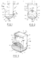
- the heat exchanger 1 shown diagrammatically in Figures 1 to 3 is for example the vaporizer-condenser main of a double distillation column air, of the dripping film type, intended to vaporize partially liquid oxygen under pressure atmospheric by condensing nitrogen under pressure of the order of 5 to 6 bars absolute.
- An example of such vaporizer-condenser is described in EP-A-0 130 122.
- the exchanger 1 comprises an exchanger body 2 of parallelepiped shape, elongated in the direction vertical, equipped with various accessories.
- treated fluid circulating in the exchanger and undergoing in the body 2 partial condensation or vaporization, that is, in the example considered, liquid oxygen partially vaporized
- these accessories are made by an inlet box 3, connected to a pipe 4 supply of monophasic treated fluid, and a separation flask 5 in its liquid and vapor phases outgoing two-phase fluid.
- a box 6 and a box 7 serving respectively at the inlet and outlet of an auxiliary fluid (in this example nitrogen) and connected respectively to pipes 8 and 9.
- the body 2 is consisting of a stack of rectangular plates 10, vertical and parallel, between which are interposed spacer waves also forming fins thermal.
- Each pair of plates 10 delimits one passage of generally flat shape.
- the passages are closed by bars 11.
- the bars corresponding to the fluid treated however leave free, on one side and above body 2, a row of inlet windows for this fluid, capped by the box 3.
- the bars 11 corresponding at the same fluid are removed on the entire face lower body 2.
- the bars 11 leave a row of entry windows free on the same side as the box 3 but at the bottom of the body 2, these windows being capped by box 6. They leave also free, on the other side and at the top of the body 2, a row of exit windows topped by the box 7.
- the body 2 is produced by stacking plates, spacers and bars, and oven brazing in one single step.
- the input-output boxes 3, 6, 7 have a general semi-cylindrical shape. They are reported on the body 2 by welding, as well as the balloon 5, which will now be described.
- the balloon 5 is produced by welded assembly three cylindrical sheets with a circular base: a part, a central plate 12 whose axis coincides with the horizontal intersection 13 of the underside of the body 2 with the vertical face of this body opposite to boxes 3 and 6, the radius of this sheet being equal to the width L of the plates 10 ( Figure 1).
- each sheet 14 extends, at each level, between its two points of intersection with the central plate 12, which starts from the edge horizontal 15 of body 2 opposite edge 13 and is ends on the opposite vertical face of this body.
- a balloon 5 which has a wide opening in one piece with defined edge as follows: a U-shaped outline that follows three sides consecutive from the base of the body 2, namely the edges bottom of the two end plates 10A, 10B and the edge 15, which consists of edges of the plates and bars 11, and a curvilinear contour which connects to the ends of the U and which consists ( Figure 3) of two arcs 18 connected by a line segment 19.
- the U-shaped contour is welded along the three corresponding edges of body 2, and the curvilinear outline is welded on the adjacent vertical face 20, which consists slices of plates 10 and bars 11.
- the face 20 will be designated by "front face" for simplify the description.
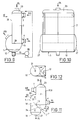
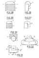
- Figures 11 to 16 show other possible configurations for tank 5, usable with a two-phase fluid at atmospheric pressure or under pressure. All these variants have in common a part 29 in the shape of a half-dome located under the part rear of the body 2, over the entire thickness thereof.
- the sheets side 14 of the half-dome are extended forward, and the balloon comprises a cylinder 30 with vertical axis which intersects the previous one along a curve 31, which is found in a plane P which passes through edge 13 and is tilted down and back at 45 °.
- half of the cylinder 30 is truncated by the body 2.
- the variant of Figure 14 further includes an appendix 14A which goes down from the point bottom of the sheet 14 and which increases the capacity liquid storage tank.
- the sheet metal cylinder 14 is extended into a complete cylinder 36 with horizontal axis beyond face 20, and is closed at the front by a bottom with semi-elliptical section 37.
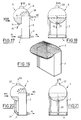
- Figures 17 to 27 show various modes of realization of the invention applied to the case where the two-phase fluid leaves the upper face 38 of the body 2, for example for a main vaporizer-condenser a double air distillation column of the type thermosyphon.
- the balloon covers the all of this face 38 and protrudes on the front face 20 of body 2, so as to present a high point and a low point located respectively above and below of face 38.
- the edge of the balloon is not welded to the end plates 10A, 10B, for the reasons explained above.
- Figures 17 to 19 is obtained by simply reversing that of the Figures 1 to 3. However, it should be noted that in the vaporizers-condensers in question, nitrogen condenses against the flow of oxygen, and therefore in the direction coming down from the exchanger. Figure 19 has been simplified to show only the configuration of the body 2 and ball 5.
- Figure 22 is obtained essentially by reversing that of Figures 11 and 12, the liquid oxygen collected in the lower part of the balloon being returned to a dome lower 40 of the exchanger, welded on the periphery of the lower face of the body 2, via a pipe 41.
- the half-cylinder 30 of the balloon is extended down to cut the extension forward, semi-cylindrical, side plates 41 of the dome 40.
- the intersection 42 found in a plane P tilted forward and down from edge 13. So a single volume of large section completely covers the upper faces, front and lower body 2.
- the transition from the half-cylinder 30 to the half-cylinder 41 can be progressive, for example rounded.
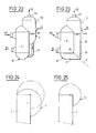
- Figures 24 to 31 illustrate ways whose forms described above can be modified: from the form of Figures 17 to 19, recalled in phantom in Figure 24, you can shift the center of cylinder, side view, down and toward rear (Figure 24), or horizontally and toward the back (Figure 25). These changes allow change the liquid storage capacity and the total size, in each particular application.
- the width of the balloon 5 can be less than the thickness of the body 2 (Figure 30), and / or the ball 5 can protrude both forwards and towards the rear of this body (Figure 31).
- Figure 32 shows how the invention can be used advantageously in contexts other than the treatment of two-phase fluids: a body heat exchanger 2, again of the plate type brazed, is intended to heat or cool a fluid monophasic coming from a device 43, for example from a compressor stage, via line 44 and returning to this device (or another device) via a pipe 45. Thanks to the laterally projecting shape of the balloon 5 provided at each end of the body 2, the connection lines 44 and 45 is greatly facilitated, and the whole has a reduced bulk. This applies well heard in case only one end of body 2 is equipped with a balloon 5.
Description
La présente invention est relative à un échangeur de chaleur du type
décrit dans le préambule de la revendication 1.The present invention relates to a heat exchanger of the type
described in the preamble of
Un tel échangeur de chaleur est connu par le DE-A-1 901 475.Such a heat exchanger is known from DE-A-1 901 475.
L'invention s'applique en particulier aux échangeurs de chaleur, du type thermosiphon ou du type à film ruisselant, traitant au moins un fluide diphasique, tels que les vaporiseurs-condenseurs des installations de distillation d'air, les évaporateurs des groupes frigorifiques, les rebouilleurs des colonnes à distiller, ou encore à certains échangeurs disposés dans des espaces réduits, tels que les échangeurs inter-étages de certains compresseurs.The invention applies in particular to heat exchangers, of the thermosiphon type or of the type with a streaming film, treating at least one two-phase fluid, such as vaporizers-condensers of installations distillation units, group evaporators refrigerators, reboilers of distillation columns, or to certain exchangers arranged in spaces reduced, such as the inter-stage exchangers of some compressors.
Dans la première application ci-dessus, les vaporiseurs-condenseurs en question doivent souvent, pour des raisons de sécurité, éviter la vaporisation à sec. De ce fait, le produit vaporisé, par exemple l'oxygène de cuve de la colonne basse pression d'une double colonne de distillation d'air, sort de l'échangeur à l'état diphasique, et doit donc passer par un séparateur de phases qui élimine les gouttelettes de la phase gazeuse et permet de recycler le liquide.In the first application above, the vaporizers-condensers in question often have to for safety reasons, avoid dry spraying. As a result, the vaporized product, for example oxygen of low pressure column tank of a double column of air distillation, leaves the exchanger in the state two-phase, and must therefore go through a separator of phases which removes droplets from the gas phase and allows the liquid to be recycled.
Dans la technique classique de ces échangeurs de chaleur, pour séparer le fluide diphasique en ses deux phases, on le collecte au moyen d'une boíte de sortie de forme générale semi-cylindrique, et on l'envoie via une tuyauterie à un ballon distinct de l'échangeur. Cette solution implique, pour la fabrication de l'échangeur, plusieurs opérations de soudage relativement délicates et conduit à une structure relativement complexe, encombrante et coûteuse.In the classic technique of these exchangers of heat, to separate the two-phase fluid into its two phases, we collect it by means of an outlet box general semi-cylindrical shape, and we send it via a piping to a tank separate from the exchanger. This solution implies, for the manufacture of the exchanger, several relatively delicate welding operations and leads to a relatively complex structure, bulky and expensive.
De même, dans la seconde application ci-dessus, le corps d'échangeur comporte généralement des boítes semi-cylindriques d'entrée/sortie de fluides à ses deux extrémités, ce qui rend compliqué le raccordement de ces boítes aux autres constituants du compresseur et rend l'ensemble de l'appareil encombrant.Likewise, in the second application above, the exchanger body generally includes semi-cylindrical fluid inlet / outlet boxes at its two ends, making connection complicated from these boxes to the other components of the compressor and makes the whole device bulky.
Le DE-A-1 901 475 décrit un échangeur de chaleur du type précité, qui n'est pas adapté au traitement de fluides sous pression.DE-A-1 901 475 describes a heat exchanger of the aforementioned type, which is not suitable for the treatment of fluids under pressure.
Le EP-A-0 566 435 montre très shématiquement un échangeur de chaleur d'un type voisin.EP-A-0 566 435 very schematically shows a heat exchanger of a neighboring type.
L'invention a pour but de fournir une
construction simple d'échangeurs de chaleur du type précité, capable
de supporter efficacement les fluides sous pression.
A cet effet, elle a pour objet un échangeur de chaleur
de ce type, caractérisé
par la partie caractérisante de la revendication 1.The object of the invention is to provide a
simple construction of heat exchangers of the aforementioned type, capable
to effectively withstand fluids under pressure.
For this purpose, it relates to a heat exchanger
of this type, characterized
by the characterizing part of
L'échangeur de chaleur suivant l'invention
peut comporter une ou plusieurs des caractéristiques
décrites dans les revendications 2 à 7. The heat exchanger according to the invention
may have one or more of the characteristics
described in
Des exemples de réalisation de l'invention vont maintenant être décrits en regard des dessins annexés, sur lesquels :
- La Figure 1 est une vue schématique de côté d'un échangeur de chaleur conforme à l'invention, suivant une première forme de réalisation;
- la Figure 2 est une vue du même échangeur prise en regardant suivant la flèche II de la Figure 1;
- la Figure 3 représente en perspective le même échangeur;
- la Figure 4 est une vue analogue à la Figure 2 d'une variante du même échangeur;
- la Figure 5 est une vue prise suivant la flèche V de la Figure 4;
- la Figure 6 est une vue de dessus de l'échangeur de la Figure 4;
- la Figure 7 est une vue partielle, analogue à la Figure 1, d'une autre variante du même échangeur;
- la Figure 8 est une vue de dessous de l'échangeur de la Figure 7;
- la Figure 9 est une vue analogue à la Figure 1 d'une autre variante du même échangeur, qui ne fait pas partie de l'invention;
- la Figure 10 est une vue prise suivant la flèche X de la Figure 9;
- la Figure 11 est une vue analogue à la Figure 1 d'un autre variante du même échangeur;
- la Figure 12 est une vue de dessous de l'échangeur de la Figure 11;
- la Figure 13 est une vue analogue à la Figure 1 d'une autre variante du même échangeur;
- la Figure 14 est une vue analogue à la Figure 13 d'une variante;
- la Figure 15 est une vue analogue à la Figure 13 d'une autre variante;
- la Figure 16 est une vue de dessous de l'échangeur de la Figure 15;
- les Figures 17 à 19 sont des vues respectivement analogues aux Figures 2 à 4, la Figure 18 étant prise suivant la flèche XVIII de la Figure 17, ces vues correspondant à une autre forme de réalisation de l'échangeur de chaleur suivant l'invention;
- la Figure 20 est une vue analogue à la Figure 17, montrant l'application de l'invention à un vaporiseur-condenseur du type thermosiphon;
- la Figure 21 est une vue prise suivant la flèche XXI de la Figure 20;
- la Figure 22 est une vue analogue à la Figure 20 d'une variante;
- la Figure 23 est une vue analogue d'une autre variante;
- les Figures 24 à 27 sont des vues schématiques partielles, de côté, illustrant des modifications possibles des échangeurs de chaleur suivant l'invention;
- les Figures 28 et 29 sont des vues de face correspondant respectivement aux Figures 26 et 27;
- la Figure 30 est une vue partielle analogue à la Figure 2 illustrant une variante de cette Figure 2;
- la Figure 31 est une vue partielle analogue à la Figure 15, illustrant une variante de cette Figure 15; et
- la Figure 32 illustre schématiquement une autre application de l'invention.
- Figure 1 is a schematic side view of a heat exchanger according to the invention, according to a first embodiment;
- Figure 2 is a view of the same exchanger taken looking at arrow II of Figure 1;
- Figure 3 shows in perspective the same exchanger;
- Figure 4 is a view similar to Figure 2 of a variant of the same exchanger;
- Figure 5 is a view taken along arrow V of Figure 4;
- Figure 6 is a top view of the exchanger of Figure 4;
- Figure 7 is a partial view, similar to Figure 1, of another variant of the same exchanger;
- Figure 8 is a bottom view of the exchanger of Figure 7;
- Figure 9 is a view similar to Figure 1 of another variant of the same exchanger, which is not part of the invention;
- Figure 10 is a view taken along arrow X in Figure 9;
- Figure 11 is a view similar to Figure 1 of another variant of the same exchanger;
- Figure 12 is a bottom view of the exchanger of Figure 11;
- Figure 13 is a view similar to Figure 1 of another variant of the same exchanger;
- Figure 14 is a view similar to Figure 13 of a variant;
- Figure 15 is a view similar to Figure 13 of another variant;
- Figure 16 is a bottom view of the exchanger of Figure 15;
- Figures 17 to 19 are views respectively similar to Figures 2 to 4, Figure 18 being taken along arrow XVIII of Figure 17, these views corresponding to another embodiment of the heat exchanger according to the invention;
- Figure 20 is a view similar to Figure 17, showing the application of the invention to a thermosyphon vaporizer-condenser;
- Figure 21 is a view taken along arrow XXI of Figure 20;
- Figure 22 is a view similar to Figure 20 of a variant;
- Figure 23 is a similar view of another variant;
- Figures 24 to 27 are partial schematic side views illustrating possible modifications of the heat exchangers according to the invention;
- Figures 28 and 29 are front views corresponding to Figures 26 and 27 respectively;
- Figure 30 is a partial view similar to Figure 2 illustrating a variant of this Figure 2;
- Figure 31 is a partial view similar to Figure 15, illustrating a variant of this Figure 15; and
- Figure 32 schematically illustrates another application of the invention.
L'échangeur de chaleur 1 représenté schématiquement
aux Figures 1 à 3 est par exemple le vaporiseur-condenseur
principal d'une double colonne de distillation
d'air, du type à film ruisselant, destiné à vaporiser
partiellement de l'oxygène liquide sous la pression
atmosphérique par condensation d'azote sous une pression
de l'ordre de 5 à 6 bars absolus. Un exemple d'un tel
vaporiseur-condenseur est décrit dans le EP-A-0 130 122.The
L'échangeur 1 comprend un corps d'échangeur
2 de forme parallélépipédique, allongé dans le sens
vertical, équipé de divers accessoires. En ce qui
concerne un fluide particulier, dit "fluide traité",
circulant dans l'échangeur et subissant dans le corps 2
une condensation ou une vaporisation partielle, c'est-à-dire,
dans l'exemple considéré, l'oxygène liquide
partiellement vaporisé, ces accessoires sont constitués
par une boíte d'entrée 3, reliée à une tuyauterie 4
d'alimentation en fluide traité monophasique, et un
ballon 5 de séparation en ses phases liquide et vapeur
du fluide diphasique sortant. Il est prévu également sur
le corps 2 une boíte 6 et une boíte 7 servant respectivement
à l'entrée et à la sortie d'un fluide auxiliaire
(dans cet exemple l'azote) et reliées respectivement à
des tuyaux 8 et 9.The
Plus particulièrement, le corps 2 est
constitué d'un empilement de plaques rectangulaires 10,
verticales et parallèles, entre lesquelles sont interposées
des ondes-entretoises formant également ailettes
thermiques. Chaque paire de plaques 10 délimite un
passage de forme générale plate. Il existe au moins deux
séries de passages, dont l'une est réservé à la circulation
du fluide traité tandis que l'autre sert à faire
circuler le fluide auxiliaire.More particularly, the
Sur leur périphérie, les passages sont fermés
par des barres 11. Les barres correspondant au fluide
traité laissent toutefois libres, sur un côté et en haut
du corps 2, une rangée de fenêtres d'entrée de ce fluide,
coiffées par la boíte 3. De plus, les barres 11 correspondant
au même fluide sont supprimées sur toute la face
inférieure du corps 2.On their periphery, the passages are closed
by
En ce qui concerne le fluide auxiliaire, les
barres 11 laissent libres une rangée de fenêtres d'entrée
du même côté que la boíte 3 mais en bas du corps 2, ces
fenêtres étant coiffées par la boíte 6. Elles laissent
également libres, de l'autre côté et en haut du corps 2,
une rangée de fenêtres de sortie coiffées par la boíte
7.With regard to the auxiliary fluid, the
Le corps 2 est réalisé par empilement des
plaques, entretoises et barres, et brasage au four en une
seule étape. Les boítes d'entrée-sortie 3, 6, 7 ont une
forme générale semi-cylindrique. Elles sont rapportées
sur le corps 2 par soudage, de même que le ballon 5, qui
va maintenant être décrit.The
Le ballon 5 est réalisé par assemblage soudé
de trois tôles cylindriques à base circulaire : d'une
part, une tôle médiane 12 dont l'axe est confondu avec
l'intersection horizontale 13 de la face inférieure du
corps 2 avec la face verticale de ce corps opposée aux
boítes 3 et 6, le rayon de cette tôle étant égale à la
largeur L des plaques 10 (Figure 1). D'autre part, deux
tôles latérales 14, également de rayon L, d'axes 15, 16
coupant perpendiculairement l'intersection 13 et tangentes,
dans leur plan diamétral, à l'extrémité inférieure
des deux plaques 10A, 10B extrêmes (Figure 2). Comme on
le voit sur les Figures 1 et 3, chaque tôle 14 s'étend,
à chaque niveau, entre ses deux points d'intersection
avec la tôle médiane 12, laquelle part de l'arête
horizontale 15 du corps 2 opposée à l'arête 13 et se
termine sur la face verticale opposée de ce corps.The
On obtient ainsi un ballon 5 qui présente une
large ouverture d'un seul tenant dont le bord est défini
comme suit : un contour en U qui suit trois côtés
consécutifs de la base du corps 2, à savoir les bords
inférieurs des deux plaques extrêmes 10A, 10B et l'arête
15, laquelle est constituée de bords des plaques et de
barres 11, et un contour curviligne qui se raccorde aux
extrémités du U et qui est constitué (Figure 3) de deux
arcs de cercle 18 reliés par un segment de droite 19. Le
contour en U est soudé le long des trois arêtes correspondantes
du corps 2, et le contour curviligne est soudé
sur la face verticale adjacente 20, laquelle est constituée
de tranches des plaques 10 et de barres 11. Dans
la suite, on désignera la face 20 par "face avant" pour
simplifier la description.A
On comprend que les passages débouchent
librement, à leur base, dans le ballon 5, lequel sert de
séparateur de phases et dépasse du corps 2 vers le bas
et vers l'avant. L'oxygène liquide recueilli est évacué
via un orifice de sortie 21 situé au point bas du ballon,
et l'oxygène gazeux est évacué via un orifice de sortie
22 prévu au voisinage de son point haut.We understand that the passages lead
freely, at their base, in the
La variante des Figures 4 à 6 ne diffère de la précédente que sous deux aspects :
- d'une part, l'oxygène liquide est introduit au sommet du corps 2 par une boíte d'entrée 23 qui coiffe toute la face supérieure de ce corps;
- d'autre part, le passage des tôles latérales 14 à la tôle médiane 12 s'effectue en plusieurs étapes, au moyen de plusieurs tôles intermédiaires 24 en secteurs cylindriques décalées angulairement, en tranches d'agrumes, les unes par rapport aux autres, à la manière d'un coude de tuyauterie. Dans l'exemple représenté, il y a de chaque côté deux tôles intermédiaires 24, avec un angle de 30° entre les tôles consécutives.
- on the one hand, liquid oxygen is introduced to the top of the
body 2 by aninlet box 23 which covers the entire upper face of this body; - on the other hand, the passage of the
side plates 14 to themiddle plate 12 is carried out in several stages, by means of severalintermediate plates 24 in cylindrical sectors offset angularly, in citrus fruit slices, with respect to each other, to the way of a pipe bend. In the example shown, there are on each side twointermediate sheets 24, with an angle of 30 ° between the consecutive sheets.
En augmentant à l'infini le nombre de tôles
intermédiaires, on aboutit à l'agencement des Figures 7
et 8, où de chaque côté l'ensemble des tôles 14 et 24 est
remplacé par un quart de sphère. De plus, sur les Figures
7 et 8, on a confondu les centres des deux quarts de
sphère, en supprimant par conséquent un côté de la tôle
cylindrique médiane 12, de sorte que la partie en saillie
latérale du ballon est une demi-sphère 25.By infinitely increasing the number of sheets
intermediate, we arrive at the arrangement of Figures 7
and 8, where on each side the set of
Cette variante convient particulièrement bien
au cas d'un simple corps d'échangeur, d'épaisseur
relativement faible, alors que la présence de la tôle 12
permet de s'adapter à volonté aux corps d'échangeur
multiples soudés les uns aux autres côte-à-côte, comme
on l'a schématisé sur la Figure 4 par la soudure verticale
26, ce qui correspond à un échangeur de chaleur à
double corps.This variant is particularly suitable
in the case of a simple exchanger body, thick
relatively weak, while the presence of
Dans les exemples des Figures 4 à 8, comme
aux Figures 1 à 3, la partie du ballon située sous le
corps 2 est constituée par trois tôles cylindriques 12,
14 à axes perpendiculaires les uns aux autres, soudées
entre elles le long des intersections des cylindres, qui
forment un V en vue en plan (Figure 8). Dans la suite,
on désignera une telle configuration par une forme "en
demi-dôme".In the examples of Figures 4 to 8, as
in Figures 1 to 3, the part of the balloon located under the
Tous les modes de réalisation décrits
jusqu'ici sont adaptés pour être utilisés non seulement,
comme c'est le cas pour les vaporiseurs-condenseurs à
film ruisselant, lorsque le fluide diphasique est
sensiblement à la pression atmosphérique, mais également
lorsque ce fluide est sous pression. En effet, la forme,
bombée dans toutes les directions, du ballon le rend apte
à supporter une pression interne, et de plus sa liaison
avec le corps d'échangeur est entièrement réalisée sur
des tranches d'extrémité de plaques 10 et sur des barres
11, de sorte que la traction exercée sur le corps du fait
de la pression interne du ballon ne s'exerce jamais sur
les plaques extrêmes 10A, 10B.All the embodiments described
so far are suitable to be used not only,
as is the case for vaporizers-condensers with
dripping film, when the two-phase fluid is
substantially at atmospheric pressure but also
when this fluid is under pressure. Indeed, the shape,
curved in all directions, the ball makes it suitable
to withstand internal pressure, and moreover its bond
with the exchanger body is entirely carried out on
plate end slices 10 and on
En revanche, pour les applications où le
fluide diphasique est à la pression atmosphérique, on
peut fixer le ballon sur les plaques 10A, 10B et adopter
une structure plus simple pour celui-ci. Ainsi, dans
l'exemple des Figures9 et 10, on utilise une simple tôle
cylindrique 12 à axe horizontal 26, le cylindre étant
tronqué jusqu'à son plan diamétral horizontal par le
corps 2 et s'étendant de la plaque 10A à la plaque 10B.
Cette tôle est soudée le long du bord inférieur arrière
15 du corps 2 et sur la face avant 20 de ce dernier. A
chaque extrémité de la tôle 12, le ballon est fermé par
un fond 27 à section axiale en demi-ellipse, soudé sur
la tranche d'extrémité de la tôle 12 et sur la plaque 10A
ou 10B correspondante. On a aussi indiqué sur la Figure
9 la pompe 28 de remontée de l'oxygène liquide recueilli
dans le ballon 5, cette pompe pouvant également être
utilisée dans chacun des modes de réalisation décrits
plus haut.However, for applications where the
two-phase fluid is at atmospheric pressure, we
can fix the balloon on the
Les Figures 11 à 16 représentent d'autres
configurations possibles pour le ballon 5, utilisables
avec un fluide diphasique à la pression atmosphérique ou
sous pression. Toutes ces variantes ont en commun une
partie 29 en forme de demi-dôme situé sous la partie
arrière du corps 2, sur toute l'épaisseur de celui-ci.Figures 11 to 16 show other
possible configurations for
Dans le cas des Figures 11 et 12, les tôles
latérales 14 du demi-dôme sont prolongées vers l'avant,
et le ballon comporte un cylindre 30 à axe vertical qui
coupe le précédent suivant une courbe 31, laquelle se
trouve dans un plan P qui passe par l'arête 13 et est
incliné vers le bas et vers l'arrière à 45°. Au-dessus de
l'arête 13, la moitié du cylindre 30 est tronquée par le
corps 2. Sur l'extrémité inférieure du cylindre 30,
située à un niveau plus bas que la tôle 14, est soudé un
fond à section semi-elliptique 32, tandis que l'extrémité
supérieure du cylindre 30 est également tronquée par une
autre tôle cylindrique 33 à axe horizontal contenu dans
la face 20 pour former un demi-dôme supérieur. Ainsi,
l'ensemble 29-30-32-33 constituant le ballon 5 est de
nouveau relié au corps 2 uniquement le long des tranches
d'extrémité inférieures des plaques 10 et sur la face
avant 20.In the case of Figures 11 and 12, the
On a également représenté sur la Figure 11,
en traits mixtes, une variante dans laquelle la partie
en saillie avant du ballon 5 ne s'élève que jusqu'au
niveau de l'arête 13. De plus, une plaque de renforcement
34 contenu dans le plan P peut être rapportée dans le
ballon, à partir de cette arête.Also shown in Figure 11,
in dashed lines, a variant in which the part
protruding before
La variante de la Figure 13 ne diffère de la
précédente que par le fait que les tôles 14 de la partie
29 sont prolongées en un demi-cylindre unique vers
l'avant, de sorte que le plan P est incliné vers le bas
et vers l'avant à partir de l'arête 13. On a aussi
indiqué un dispositif approprié 35 de séparation de
gouttelettes, disposé dans la partie semi-cylindrique du
cylindre 30.The variant of Figure 13 does not differ from the
previous than by the fact that the
La variante de la Figure 14 comprend de plus
un appendice 14A qui part vers le bas à partir du point
bas de la tôle 14 et qui permet d'augmenter la capacité
de stockage de liquide du ballon.The variant of Figure 14 further includes
an appendix 14A which goes down from the point
bottom of the
Dans l'exemple des Figures 15 et 16, le
cylindre des tôles 14 est prolongé en un cylindre complet
36 à axe horizontal au-delà de la face 20, et est fermé
à l'avant par un fond à section semi-elliptique 37.In the example in Figures 15 and 16, the
Les Figures 17 à 27 représentent divers modes
de réalisation de l'invention appliqués au cas où le
fluide diphasique sort de la face supérieure 38 du corps
2, par exemple pour un vaporiseur-condenseur principal
d'une double colonne de distillation d'air du type
thermosiphon. Dans chaque cas, le ballon coiffe la
totalité de cette face 38 et dépasse sur la face avant
20 du corps 2, de façon à présenter un point haut et un
point bas situés respectivement au-dessus et au-dessous
de la face 38. De plus, dans chaque cas, le bord du
ballon n'est pas soudé sur les plaques d'extrémité 10A,
10B, pour les raisons expliquées plus haut.Figures 17 to 27 show various modes
of realization of the invention applied to the case where the
two-phase fluid leaves the
Le mode de réalisation des Figures 17 à 19
est obtenu par simple renversement de celui des Figures
1 à 3. Il est toutefois à noter que, dans les
vaporiseurs-condenseurs en question, l'azote se condense
à contre-courant de l'oxygène, et donc dans le sens
descendant de l'échangeur. La Figure 19 a été simplifiée
pour ne faire apparaitre que la configuration du corps
2 et du ballon 5. The embodiment of Figures 17 to 19
is obtained by simply reversing that of the Figures
1 to 3. However, it should be noted that in the
vaporizers-condensers in question, nitrogen condenses
against the flow of oxygen, and therefore in the direction
coming down from the exchanger. Figure 19 has been simplified
to show only the configuration of the
Dans la variante des Figures 20 et 21, on a
simplement ajouté une conduite 39 qui part de l'orifice
21 et qui sert au renvoi de l'oxygène liquide recueilli
dans le ballon 5 à la boíte 3 d'entrée d'oxygène liquide
dans le corps d'échangeur.In the variant of Figures 20 and 21, we have
simply added a
De même, la variante de la Figure 22 est
obtenue pour l'essentiel par renversement de celle des
Figures 11 et 12, l'oxygène liquide recueilli dans la
partie basse du ballon étant renvoyée dans un dôme
inférieur 40 de l'échangeur, soudé sur le pourtour de la
face inférieur du corps 2, via une conduite 41.Similarly, the variant of Figure 22 is
obtained essentially by reversing that of
Figures 11 and 12, the liquid oxygen collected in the
lower part of the balloon being returned to a dome
lower 40 of the exchanger, welded on the periphery of the
lower face of the
Dans la variante de la Figure 23, le demi-cylindre
30 du ballon est prolongé vers le bas jusqu'à
couper le prolongement vers l'avant, semi-cylindrique,
des tôles latérales 41 du dôme 40. L'intersection 42 se
trouve dans un plan P incliné vers l'avant et vers le bas
à partir de l'arête 13. Ainsi, un volume unique de grande
section coiffe en totalité les faces supérieure, avant
et inférieure du corps 2.In the variant of Figure 23, the half-
Dans les agencements des Figures 22 et 23,
l'oxygène liquide à vaporiser est introduit dans le
ballon 5, via une conduite 4A.In the arrangements of Figures 22 and 23,
the liquid oxygen to be vaporized is introduced into the
Comme indiqué en traits mixtes sur la Figure
23, le passage du demi-cylindre 30 au demi-cylindre 41
peut être progressif, par exemple arrondi.As shown in phantom in Figure
23, the transition from the half-
Les Figures 24 à 31 illustrent des manières dont les formes décrites plus haut peuvent être modifiées: à partir de la forme des Figures 17 à 19, rappelée en traits mixtes sur la Figure 24, on peut décaler le centre du cylindre, en vue latérale, vers le bas et vers l'arrière (Figure 24), ou bien horizontalement et vers l'arrière (Figure 25). Ces modifications permettent de changer la capacité de stockage de liquide et l'encombrement total, dans chaque application particulière.Figures 24 to 31 illustrate ways whose forms described above can be modified: from the form of Figures 17 to 19, recalled in phantom in Figure 24, you can shift the center of cylinder, side view, down and toward rear (Figure 24), or horizontally and toward the back (Figure 25). These changes allow change the liquid storage capacity and the total size, in each particular application.
De plus, comme illustré aux Figures 26 à 29, toutes les formes peuvent être déformées par affinité, horizontale ou verticale, dans un sens ou dans l'autre, ce qui transforme les cylindres circulaires en cylindres elliptiques et les sphères en ellipsoides.In addition, as illustrated in Figures 26 to 29, all shapes can be distorted by affinity, horizontal or vertical, one way or the other, which turns circular cylinders into cylinders ellipticals and ellipsoid spheres.
Par ailleurs, la largeur du ballon 5 peut
être inférieure à l'épaisseur du corps 2 (Figure 30),
et/ou le ballon 5 peut dépasser à la fois vers l'avant et
vers l'arrière de ce corps (Figure 31).Furthermore, the width of the
La Figure 32 montre comment l'invention peut
être utilisée avantageusement dans d'autres contextes que
le traitement de fluides diphasiques : un corps
d'échangeur de chaleur 2, de nouveau du type à plaques
brasées, est destiné à chauffer ou refroidir un fluide
monophasique arrivant d'un appareil 43, par exemple d'un
étage de compresseur, via une conduite 44 et retournant
à cet appareil (ou à un autre appareil) via une conduite
45. Grâce à la forme latéralement débordante du ballon
5 prévu à chaque extrémité du corps 2, le raccordement
des conduites 44 et 45 est grandement facilité, et
l'ensemble a un encombrement réduit. Ceci s'applique bien
entendu au cas où une seule extrémité du corps 2 serait
équipée d'un ballon 5.Figure 32 shows how the invention can
be used advantageously in contexts other than
the treatment of two-phase fluids: a
Claims (7)
- Heat exchanger, of the type comprising on the one hand a body portion (2) in the form of a dihedron with, on a first face of the dihedron, at least one fluid intake/discharge port, said body portion (2) being formed by a stack of parallel plates (10) defining between them flat passages, crosspieces arranged between said plates and bars (11) for closing the passages, the bars corresponding to said fluid leaving free said port, and on the other hand an intake/discharge flask (5) for said fluid tightly covering the port and straddling one of the edges (13, 15) of the dihedron and connected in tightly joining manner to each of the faces of the dihedron, located on other side of said edge, characterized in that the flask is implemented by a combination of sheets (12, 14; 12, 14, 24; 12, 14, 25; 12, 14, 30, 32, 33; 12, 14, 36, 37) having a cylindrical, spherical and/or ellipsoidal shape, which are welded together and is only connected to said body portion (2) on one of the faces thereof formed by end sections of plates (10) and by bars (11).
- Heat exchanger according to claim 1, wherein said body portion (2) forms a second dihedron between said first face and a third, adjacent face, characterized in that the flask (5) also projects, with repsect to said body portion, beyond the edge (15) of the second dihedron, which it straddles.
- Heat exchanger according to claim 1, characterized in that the flask (5) is connected to said first face along two lines perpendicular to the edge (13, 15) of the or each dihedron, particularly along two edges of said face perpendicular to the edge.
- Heat exchanger according to any one of the claims 1 to 3, characterized in that the flask is constituted by three cylindrical sheets (12, 14), the two end sheets (14) having axes perpendicularly intersecting the axis of the median sheet (12).
- Heat exchanger according to any one of the claims 1 to 4, constituting a heat exchanger, whereof the said body portion (2) is parallelepipedic with said first face at its upper or lower end, said fluid being a two-phase fluid passing out of said body portion by said port, characterized in that the flask (5) has a liquid outlet (21) in the vicinity of its bottom point and a gas outlet (22) in the vicinity of its top point.
- Heat exchanger according to claim 5, wherein said first face is the upper face of said body portion, characterized in that the liquid outlet (21) is connected to a liquid inlet (3) located at a lower level of the body (2).
- Heat exchanger according to claim 6, characterized in that the flask (5) also covers the lower face of the body (2), which is provided with said liquid inlet.
Applications Claiming Priority (2)
| Application Number | Priority Date | Filing Date | Title |
|---|---|---|---|
| FR9415423A FR2728669B1 (en) | 1994-12-21 | 1994-12-21 | FLUID CIRCULATION APPARATUS |
| FR9415423 | 1994-12-21 |
Publications (2)
| Publication Number | Publication Date |
|---|---|
| EP0718582A1 EP0718582A1 (en) | 1996-06-26 |
| EP0718582B1 true EP0718582B1 (en) | 1999-10-20 |
Family
ID=9470072
Family Applications (1)
| Application Number | Title | Priority Date | Filing Date |
|---|---|---|---|
| EP95402780A Expired - Lifetime EP0718582B1 (en) | 1994-12-21 | 1995-12-11 | Heatexchanger |
Country Status (9)
| Country | Link |
|---|---|
| US (1) | US5765631A (en) |
| EP (1) | EP0718582B1 (en) |
| JP (2) | JPH08291980A (en) |
| CN (1) | CN1133429A (en) |
| AU (1) | AU703255B2 (en) |
| CA (1) | CA2165719A1 (en) |
| DE (1) | DE69512876T2 (en) |
| FR (1) | FR2728669B1 (en) |
| ZA (1) | ZA9510613B (en) |
Cited By (1)
| Publication number | Priority date | Publication date | Assignee | Title |
|---|---|---|---|---|
| DE102012003417A1 (en) | 2012-02-17 | 2013-08-22 | Uhde Inventa-Fischer Gmbh | Process for the preparation of a high molecular weight, heteroaromatic polyester or copolyester |
Families Citing this family (15)
| Publication number | Priority date | Publication date | Assignee | Title |
|---|---|---|---|---|
| FR2774755B1 (en) * | 1998-02-09 | 2000-04-28 | Air Liquide | PERFECTED BRAZED PLATE CONDENSER AND ITS APPLICATION TO DOUBLE AIR DISTILLATION COLUMNS |
| FR2786859B1 (en) | 1998-12-07 | 2001-01-19 | Air Liquide | PLATE HEAT EXCHANGER FOR AN AIR SEPARATION APPARATUS |
| FR2789165B1 (en) * | 1999-02-01 | 2001-03-09 | Air Liquide | HEAT EXCHANGER, PARTICULARLY PLATE HEAT EXCHANGER OF AN AIR SEPARATION APPARATUS |
| EP1037004B1 (en) * | 1999-03-17 | 2003-08-06 | Linde Aktiengesellschaft | Apparatus and process for gas mixture separation at low temperature |
| DE50003157D1 (en) | 1999-03-17 | 2003-09-11 | Linde Ag | Device and method for decomposing a gas mixture at low temperature |
| FR2797943A1 (en) * | 1999-08-24 | 2001-03-02 | Air Liquide | Evaporator-condenser for air distillation installation comprises dihedral body with fluid passage opening on first face hermetically covered by cylindrical connecting box |
| US6349566B1 (en) | 2000-09-15 | 2002-02-26 | Air Products And Chemicals, Inc. | Dephlegmator system and process |
| US6832647B2 (en) * | 2002-04-02 | 2004-12-21 | Modine Manufacturing Company | Integrated condenser/separator for fuel cell exhaust gases |
| US7237406B2 (en) * | 2004-09-07 | 2007-07-03 | Modine Manufacturing Company | Condenser/separator and method |
| MX2008003973A (en) * | 2005-09-23 | 2008-11-06 | Heatric | Multiple reactor chemical production system. |
| FR2891901B1 (en) * | 2005-10-06 | 2014-03-14 | Air Liquide | METHOD FOR VAPORIZATION AND / OR CONDENSATION IN A HEAT EXCHANGER |
| US9476609B2 (en) * | 2009-05-06 | 2016-10-25 | Api Heat Transfer Inc. | Water separator and system |
| US8561420B2 (en) * | 2009-05-08 | 2013-10-22 | Honda Motor Co., Ltd. | Evaporator assembly for an HVAC system |
| WO2016146238A1 (en) * | 2015-03-13 | 2016-09-22 | Linde Aktiengesellschaft | Distillation column system, equipment and method for generating oxygen by means of low-temperature separation of air |
| FR3060553B1 (en) * | 2016-12-15 | 2021-02-19 | Air Liquide | EXCHANGER-REACTOR INCLUDING CONNECTORS WITH SUPPORTS |
Family Cites Families (9)
| Publication number | Priority date | Publication date | Assignee | Title |
|---|---|---|---|---|
| FR1524343A (en) * | 1967-03-31 | 1968-05-10 | Air Liquide | Indirect heat exchange set |
| US3568462A (en) * | 1967-11-22 | 1971-03-09 | Mc Donnell Douglas Corp | Fractionating device |
| US3490522A (en) * | 1968-02-20 | 1970-01-20 | United Aircraft Corp | Heat exchanger pass separator construction |
| DE1901475A1 (en) * | 1969-01-14 | 1970-08-27 | Messer Griesheim Gmbh | Distributing a two-phase flow to plate heat - exchangers |
| JP2531398B2 (en) * | 1986-10-28 | 1996-09-04 | 石川島播磨重工業株式会社 | Plate fin type heat exchanger and method for manufacturing the same |
| US4773474A (en) * | 1987-08-12 | 1988-09-27 | Modine Manufacturing Company | Snap on fillerneck assembly for radiators |
| FR2665757B1 (en) * | 1990-08-08 | 1997-01-17 | Valeo Thermique Moteur Sa | VERTICAL CIRCULATION REFRIGERANT FLUID CONDENSER AND MANUFACTURING METHOD. |
| FR2690231B1 (en) * | 1992-04-17 | 1994-06-03 | Air Liquide | RUNOFF HEAT EXCHANGER AND AIR DISTILLATION SYSTEM COMPRISING SUCH AN EXCHANGER. |
| TW216453B (en) * | 1992-07-08 | 1993-11-21 | Air Prod & Chem | Integrated plate-fin heat exchange reformation |
-
1994
- 1994-12-21 FR FR9415423A patent/FR2728669B1/en not_active Expired - Fee Related
-
1995
- 1995-12-11 EP EP95402780A patent/EP0718582B1/en not_active Expired - Lifetime
- 1995-12-11 DE DE69512876T patent/DE69512876T2/en not_active Expired - Lifetime
- 1995-12-13 AU AU40403/95A patent/AU703255B2/en not_active Ceased
- 1995-12-13 ZA ZA9510613A patent/ZA9510613B/en unknown
- 1995-12-20 US US08/575,476 patent/US5765631A/en not_active Expired - Lifetime
- 1995-12-20 CA CA002165719A patent/CA2165719A1/en not_active Abandoned
- 1995-12-20 CN CN95120870A patent/CN1133429A/en active Pending
- 1995-12-21 JP JP7333470A patent/JPH08291980A/en active Pending
-
2002
- 2002-12-04 JP JP2002352110A patent/JP3746760B2/en not_active Expired - Fee Related
Non-Patent Citations (1)
| Title |
|---|
| H. Titze, "Elemente des Apparatebaues", Springer-Verlag, 1963, pages 127 à 129 * |
Cited By (1)
| Publication number | Priority date | Publication date | Assignee | Title |
|---|---|---|---|---|
| DE102012003417A1 (en) | 2012-02-17 | 2013-08-22 | Uhde Inventa-Fischer Gmbh | Process for the preparation of a high molecular weight, heteroaromatic polyester or copolyester |
Also Published As
| Publication number | Publication date |
|---|---|
| ZA9510613B (en) | 1997-09-15 |
| EP0718582A1 (en) | 1996-06-26 |
| AU4040395A (en) | 1996-06-27 |
| JP2003227693A (en) | 2003-08-15 |
| FR2728669B1 (en) | 1997-04-11 |
| US5765631A (en) | 1998-06-16 |
| DE69512876D1 (en) | 1999-11-25 |
| JP3746760B2 (en) | 2006-02-15 |
| DE69512876T2 (en) | 2000-06-15 |
| AU703255B2 (en) | 1999-03-25 |
| CA2165719A1 (en) | 1996-06-22 |
| FR2728669A1 (en) | 1996-06-28 |
| JPH08291980A (en) | 1996-11-05 |
| CN1133429A (en) | 1996-10-16 |
Similar Documents
| Publication | Publication Date | Title |
|---|---|---|
| EP0718582B1 (en) | Heatexchanger | |
| EP0546947B1 (en) | Indirect plate-type heat exchanger | |
| WO2007042698A1 (en) | Method for evaporation and/or condensation in a heat exchanger | |
| EP1008826B1 (en) | Falling film vaporizer and air distillation plant | |
| EP0774102B1 (en) | Condenser with a built-in receiver for a motor vehicle air conditioning unit | |
| FR2665755A1 (en) | Apparatus for producing nitrogen | |
| EP0019508B1 (en) | Thermal-exchange assembly of the plate heat exchanger type | |
| FR2664371A1 (en) | Heat exchanger, mounted on a vehicle, of the parallel flow type | |
| FR2718836A1 (en) | Improved heat exchanger with brazed plates. | |
| FR3065795B1 (en) | IMPROVED WAVE JUNCTION HEAT EXCHANGER, AIR SEPARATION INSTALLATION THEREFOR, AND METHOD FOR MANUFACTURING SUCH EXCHANGER | |
| EP1179724B1 (en) | Heat exchanger with multiple heat exchange blocks with fluid inlet manifold providing uniform distribution, and vaporizer-condenser comprising same | |
| EP1406057B1 (en) | Plate heat exchanger having a thick fin | |
| EP1088578A1 (en) | Vaporizer-condenser with thermosiphon and corresponding air distillation plant | |
| EP0738862B1 (en) | Heat exchanger with brazed plates | |
| EP0718583B1 (en) | Apparatus for the circulation of a fluid | |
| FR2774755A1 (en) | PERFECTED BRAZED PLATE CONDENSER AND ITS APPLICATION TO DOUBLE AIR DISTILLATION COLUMNS | |
| FR2803376A1 (en) | STACKED FLAT TUBE EVAPORATOR WITH TWO OPPOSED FLUID BOXES | |
| FR2515804A1 (en) | HEAT EXCHANGER, COMPRISING A BEAM OF TUBES ORIENTED PARALLEMENT, WHICH CAN BE SOLICATED BY AIR | |
| EP1230522B1 (en) | Evaporator-condenser and corresponding air distillation installation | |
| FR2793548A1 (en) | Plate vaporizer-condenser operating as a thermosiphon in which the exchange corrugations of the second passage are vertical and the exchange body has two inlet boxes spaced over its length | |
| WO2009063146A1 (en) | Heat exchanger and cryogenic-distillation-based air separation device including one such exchanger | |
| WO2020174173A1 (en) | Matrix integrating at least one heat exchange function and one distillation function | |
| EP0217777A1 (en) | Heat pipe with a capillary structure | |
| FR3133077A3 (en) | Heat exchanger with improved heat exchange structure | |
| FR3093170A1 (en) | Matrix integrating at least one heat exchange function and one distillation function |
Legal Events
| Date | Code | Title | Description |
|---|---|---|---|
| PUAI | Public reference made under article 153(3) epc to a published international application that has entered the european phase |
Free format text: ORIGINAL CODE: 0009012 |
|
| AK | Designated contracting states |
Kind code of ref document: A1 Designated state(s): BE DE ES GB IT NL SE |
|
| 17P | Request for examination filed |
Effective date: 19960507 |
|
| RIN1 | Information on inventor provided before grant (corrected) |
Inventor name: LEHMAN, JEAN-YVES Inventor name: GERARD, CLAUDE |
|
| 17Q | First examination report despatched |
Effective date: 19980206 |
|
| GRAG | Despatch of communication of intention to grant |
Free format text: ORIGINAL CODE: EPIDOS AGRA |
|
| GRAG | Despatch of communication of intention to grant |
Free format text: ORIGINAL CODE: EPIDOS AGRA |
|
| GRAH | Despatch of communication of intention to grant a patent |
Free format text: ORIGINAL CODE: EPIDOS IGRA |
|
| GRAH | Despatch of communication of intention to grant a patent |
Free format text: ORIGINAL CODE: EPIDOS IGRA |
|
| GRAA | (expected) grant |
Free format text: ORIGINAL CODE: 0009210 |
|
| AK | Designated contracting states |
Kind code of ref document: B1 Designated state(s): BE DE ES GB IT NL SE |
|
| PG25 | Lapsed in a contracting state [announced via postgrant information from national office to epo] |
Ref country code: SE Free format text: THE PATENT HAS BEEN ANNULLED BY A DECISION OF A NATIONAL AUTHORITY Effective date: 19991020 Ref country code: IT Free format text: LAPSE BECAUSE OF FAILURE TO SUBMIT A TRANSLATION OF THE DESCRIPTION OR TO PAY THE FEE WITHIN THE PRESCRIBED TIME-LIMIT;WARNING: LAPSES OF ITALIAN PATENTS WITH EFFECTIVE DATE BEFORE 2007 MAY HAVE OCCURRED AT ANY TIME BEFORE 2007. THE CORRECT EFFECTIVE DATE MAY BE DIFFERENT FROM THE ONE RECORDED. Effective date: 19991020 Ref country code: ES Free format text: THE PATENT HAS BEEN ANNULLED BY A DECISION OF A NATIONAL AUTHORITY Effective date: 19991020 |
|
| GBT | Gb: translation of ep patent filed (gb section 77(6)(a)/1977) |
Effective date: 19991028 |
|
| REF | Corresponds to: |
Ref document number: 69512876 Country of ref document: DE Date of ref document: 19991125 |
|
| PG25 | Lapsed in a contracting state [announced via postgrant information from national office to epo] |
Ref country code: BE Free format text: LAPSE BECAUSE OF NON-PAYMENT OF DUE FEES Effective date: 19991231 |
|
| BERE | Be: lapsed |
Owner name: NORDON CRYOGENIE SNC Effective date: 19991231 Owner name: S.A. L' AIR LIQUIDE POUR L'ETUDE ET L'EXPLOITATION Effective date: 19991231 |
|
| PG25 | Lapsed in a contracting state [announced via postgrant information from national office to epo] |
Ref country code: NL Free format text: LAPSE BECAUSE OF NON-PAYMENT OF DUE FEES Effective date: 20000701 |
|
| PLBE | No opposition filed within time limit |
Free format text: ORIGINAL CODE: 0009261 |
|
| STAA | Information on the status of an ep patent application or granted ep patent |
Free format text: STATUS: NO OPPOSITION FILED WITHIN TIME LIMIT |
|
| NLV4 | Nl: lapsed or anulled due to non-payment of the annual fee |
Effective date: 20000701 |
|
| 26N | No opposition filed | ||
| REG | Reference to a national code |
Ref country code: GB Ref legal event code: IF02 |
|
| PGFP | Annual fee paid to national office [announced via postgrant information from national office to epo] |
Ref country code: DE Payment date: 20121207 Year of fee payment: 18 |
|
| PGFP | Annual fee paid to national office [announced via postgrant information from national office to epo] |
Ref country code: GB Payment date: 20121219 Year of fee payment: 18 |
|
| REG | Reference to a national code |
Ref country code: DE Ref legal event code: R119 Ref document number: 69512876 Country of ref document: DE |
|
| GBPC | Gb: european patent ceased through non-payment of renewal fee |
Effective date: 20131211 |
|
| REG | Reference to a national code |
Ref country code: DE Ref legal event code: R119 Ref document number: 69512876 Country of ref document: DE Effective date: 20140701 |
|
| PG25 | Lapsed in a contracting state [announced via postgrant information from national office to epo] |
Ref country code: DE Free format text: LAPSE BECAUSE OF NON-PAYMENT OF DUE FEES Effective date: 20140701 |
|
| PG25 | Lapsed in a contracting state [announced via postgrant information from national office to epo] |
Ref country code: GB Free format text: LAPSE BECAUSE OF NON-PAYMENT OF DUE FEES Effective date: 20131211 |