EP0718256B1 - Ceramic sliding member and process of fabricating the same - Google Patents
Ceramic sliding member and process of fabricating the same Download PDFInfo
- Publication number
- EP0718256B1 EP0718256B1 EP95309355A EP95309355A EP0718256B1 EP 0718256 B1 EP0718256 B1 EP 0718256B1 EP 95309355 A EP95309355 A EP 95309355A EP 95309355 A EP95309355 A EP 95309355A EP 0718256 B1 EP0718256 B1 EP 0718256B1
- Authority
- EP
- European Patent Office
- Prior art keywords
- ceramic
- film
- pyrolytic carbon
- pyrolysis
- sliding member
- Prior art date
- Legal status (The legal status is an assumption and is not a legal conclusion. Google has not performed a legal analysis and makes no representation as to the accuracy of the status listed.)
- Expired - Lifetime
Links
Images

Classifications
-
- C—CHEMISTRY; METALLURGY
- C04—CEMENTS; CONCRETE; ARTIFICIAL STONE; CERAMICS; REFRACTORIES
- C04B—LIME, MAGNESIA; SLAG; CEMENTS; COMPOSITIONS THEREOF, e.g. MORTARS, CONCRETE OR LIKE BUILDING MATERIALS; ARTIFICIAL STONE; CERAMICS; REFRACTORIES; TREATMENT OF NATURAL STONE
- C04B41/00—After-treatment of mortars, concrete, artificial stone or ceramics; Treatment of natural stone
- C04B41/009—After-treatment of mortars, concrete, artificial stone or ceramics; Treatment of natural stone characterised by the material treated
-
- C—CHEMISTRY; METALLURGY
- C04—CEMENTS; CONCRETE; ARTIFICIAL STONE; CERAMICS; REFRACTORIES
- C04B—LIME, MAGNESIA; SLAG; CEMENTS; COMPOSITIONS THEREOF, e.g. MORTARS, CONCRETE OR LIKE BUILDING MATERIALS; ARTIFICIAL STONE; CERAMICS; REFRACTORIES; TREATMENT OF NATURAL STONE
- C04B41/00—After-treatment of mortars, concrete, artificial stone or ceramics; Treatment of natural stone
- C04B41/45—Coating or impregnating, e.g. injection in masonry, partial coating of green or fired ceramics, organic coating compositions for adhering together two concrete elements
- C04B41/52—Multiple coating or impregnating multiple coating or impregnating with the same composition or with compositions only differing in the concentration of the constituents, is classified as single coating or impregnation
-
- C—CHEMISTRY; METALLURGY
- C04—CEMENTS; CONCRETE; ARTIFICIAL STONE; CERAMICS; REFRACTORIES
- C04B—LIME, MAGNESIA; SLAG; CEMENTS; COMPOSITIONS THEREOF, e.g. MORTARS, CONCRETE OR LIKE BUILDING MATERIALS; ARTIFICIAL STONE; CERAMICS; REFRACTORIES; TREATMENT OF NATURAL STONE
- C04B41/00—After-treatment of mortars, concrete, artificial stone or ceramics; Treatment of natural stone
- C04B41/80—After-treatment of mortars, concrete, artificial stone or ceramics; Treatment of natural stone of only ceramics
- C04B41/81—Coating or impregnation
- C04B41/89—Coating or impregnation for obtaining at least two superposed coatings having different compositions
-
- C—CHEMISTRY; METALLURGY
- C23—COATING METALLIC MATERIAL; COATING MATERIAL WITH METALLIC MATERIAL; CHEMICAL SURFACE TREATMENT; DIFFUSION TREATMENT OF METALLIC MATERIAL; COATING BY VACUUM EVAPORATION, BY SPUTTERING, BY ION IMPLANTATION OR BY CHEMICAL VAPOUR DEPOSITION, IN GENERAL; INHIBITING CORROSION OF METALLIC MATERIAL OR INCRUSTATION IN GENERAL
- C23C—COATING METALLIC MATERIAL; COATING MATERIAL WITH METALLIC MATERIAL; SURFACE TREATMENT OF METALLIC MATERIAL BY DIFFUSION INTO THE SURFACE, BY CHEMICAL CONVERSION OR SUBSTITUTION; COATING BY VACUUM EVAPORATION, BY SPUTTERING, BY ION IMPLANTATION OR BY CHEMICAL VAPOUR DEPOSITION, IN GENERAL
- C23C16/00—Chemical coating by decomposition of gaseous compounds, without leaving reaction products of surface material in the coating, i.e. chemical vapour deposition [CVD] processes
- C23C16/02—Pretreatment of the material to be coated
- C23C16/0272—Deposition of sub-layers, e.g. to promote the adhesion of the main coating
-
- C—CHEMISTRY; METALLURGY
- C23—COATING METALLIC MATERIAL; COATING MATERIAL WITH METALLIC MATERIAL; CHEMICAL SURFACE TREATMENT; DIFFUSION TREATMENT OF METALLIC MATERIAL; COATING BY VACUUM EVAPORATION, BY SPUTTERING, BY ION IMPLANTATION OR BY CHEMICAL VAPOUR DEPOSITION, IN GENERAL; INHIBITING CORROSION OF METALLIC MATERIAL OR INCRUSTATION IN GENERAL
- C23C—COATING METALLIC MATERIAL; COATING MATERIAL WITH METALLIC MATERIAL; SURFACE TREATMENT OF METALLIC MATERIAL BY DIFFUSION INTO THE SURFACE, BY CHEMICAL CONVERSION OR SUBSTITUTION; COATING BY VACUUM EVAPORATION, BY SPUTTERING, BY ION IMPLANTATION OR BY CHEMICAL VAPOUR DEPOSITION, IN GENERAL
- C23C16/00—Chemical coating by decomposition of gaseous compounds, without leaving reaction products of surface material in the coating, i.e. chemical vapour deposition [CVD] processes
- C23C16/22—Chemical coating by decomposition of gaseous compounds, without leaving reaction products of surface material in the coating, i.e. chemical vapour deposition [CVD] processes characterised by the deposition of inorganic material, other than metallic material
- C23C16/26—Deposition of carbon only
-
- C—CHEMISTRY; METALLURGY
- C04—CEMENTS; CONCRETE; ARTIFICIAL STONE; CERAMICS; REFRACTORIES
- C04B—LIME, MAGNESIA; SLAG; CEMENTS; COMPOSITIONS THEREOF, e.g. MORTARS, CONCRETE OR LIKE BUILDING MATERIALS; ARTIFICIAL STONE; CERAMICS; REFRACTORIES; TREATMENT OF NATURAL STONE
- C04B2111/00—Mortars, concrete or artificial stone or mixtures to prepare them, characterised by specific function, property or use
- C04B2111/00241—Physical properties of the materials not provided for elsewhere in C04B2111/00
- C04B2111/00344—Materials with friction-reduced moving parts, e.g. ceramics lubricated by impregnation with carbon
- C04B2111/00353—Sliding parts
-
- Y—GENERAL TAGGING OF NEW TECHNOLOGICAL DEVELOPMENTS; GENERAL TAGGING OF CROSS-SECTIONAL TECHNOLOGIES SPANNING OVER SEVERAL SECTIONS OF THE IPC; TECHNICAL SUBJECTS COVERED BY FORMER USPC CROSS-REFERENCE ART COLLECTIONS [XRACs] AND DIGESTS
- Y10—TECHNICAL SUBJECTS COVERED BY FORMER USPC
- Y10T—TECHNICAL SUBJECTS COVERED BY FORMER US CLASSIFICATION
- Y10T428/00—Stock material or miscellaneous articles
- Y10T428/26—Web or sheet containing structurally defined element or component, the element or component having a specified physical dimension
- Y10T428/263—Coating layer not in excess of 5 mils thick or equivalent
- Y10T428/264—Up to 3 mils
- Y10T428/265—1 mil or less
-
- Y—GENERAL TAGGING OF NEW TECHNOLOGICAL DEVELOPMENTS; GENERAL TAGGING OF CROSS-SECTIONAL TECHNOLOGIES SPANNING OVER SEVERAL SECTIONS OF THE IPC; TECHNICAL SUBJECTS COVERED BY FORMER USPC CROSS-REFERENCE ART COLLECTIONS [XRACs] AND DIGESTS
- Y10—TECHNICAL SUBJECTS COVERED BY FORMER USPC
- Y10T—TECHNICAL SUBJECTS COVERED BY FORMER US CLASSIFICATION
- Y10T428/00—Stock material or miscellaneous articles
- Y10T428/30—Self-sustaining carbon mass or layer with impregnant or other layer
Definitions
- the present invention relates to a highly durable sliding member made of a ceramic material, and a process of fabricating such ceramic sliding member.
- Ceramics which are generally excellent in wear resistance, heat resistance and corrosion resistance, have been widely employed as a material for various members which slidably move on other members.
- a typical application of ceramic materials for such sliding members is found in the manufacture of bibcocks or water faucets.
- a sliding member made of most common oxide ceramics such as alumina, mullite, silica and glass is usually coated at its sliding surface with an oily lubricant such as a grease, for assuring a high degree of slidability with respect to the surface of the other member.
- an oily lubricant such as a grease
- JP-A-63-9781 discloses a sliding member of a porous ceramic structure filled with carbon fluoride, carbon or boron nitride
- JP-U-63-51970, JP-U-63-180776 and JP-U-2-136036 disclose a sliding member having a sliding surface coated with a layer of fluorocarbon resin, molybdenum disulfide, graphite, TiN or SiC.
- JP-A-3-223190 and JP-A-4-165170 show a sliding member having a sliding surface coated with a film of amorphous diamond or diamond-like carbon (DLC).
- DLC diamond-like carbon
- the sliding member having a porous ceramic structure tends to cause leakage of a fluid when used as a water faucet, for example, and is not satisfactory in mechanical strength and wear resistance.
- the sliding member whose sliding surface is partly constituted by a solid material having a lubricating property does not have a sufficiently reduced sliding resistance in the absence of a grease.
- sliding members having a coating layer of a non-oxide hard wear-resistant material such as TiN or SiC or a coating film of a special wear-resistant high-hardness material such as amorphous diamond or DLC exhibit comparatively excellent sliding characteristics
- the manufacture of these sliding members requires sophisticated techniques such as a plasma process (chemical vapor deposition) or an ion beam process (physical vapor deposition), and tends to be complicated and costly, leading to low commercial availability of these sliding members.
- the prior art technologies which have been discussed above may be roughly classified into the following two categories: That is, the first of these categories uses an oxide ceramic material as a hard wear-resistant base member or substrate, and a solid lubricating substance or material which constitutes a part of the surface of the base member or substrate, so as to provide a sliding surface whose sliding resistance is considerably small.
- This type of sliding member according to the technology in this first category is shown in enlargement in an elevational view of Fig. 1, which is taken in cross section in a plane perpendicular to a sliding surface 1 of the sliding member.
- ceramic crystal grains 2 consisting of wear-resistant oxide and/or silicate are exposed on the sliding surface 1, together with a lubricant 4.
- the surface structure of the sliding member also comprises grain boundary bonding portions 3, which may or may not be exposed to the sliding surface 1.
- a thin film consisting of a hard wear-resistant material such as silicon carbide, amorphous diamond or diamond-like carbon (DLC) is formed on the surface of a ceramic substrate, as a sliding surface which exhibits high wear resistance and low sliding resistance.
- Fig. 2 wherein the thin film of hard wear-resistant material is indicated at 5, while the sliding surface provided by this thin film 5 is indicated generally at 1.
- the latter type of sliding member as shown in Fig. 2 is more excellent, but is not practically available due to a considerably high cost of manufacture, as explained above.
- the present invention was developed in the light of the prior art discussed above. An extensive research by the present inventors revealed an appreciable improvement in the wear resistance of the sliding surface provided by an electrically conductive pyrolytic carbon film of a graphite-like layered structure, if this pyrolytic carbon film is formed on an intermediate film formed on a ceramic substrate. It was found that the wear resistance of the pyrolytic carbon film will increase up to a level as high as that of silicon carbide.
- this invention provides a ceramic sliding member comprising: (a) a ceramic substrate consisting of a dense sintered body of a ceramic material consisting essentially of metal oxide and/or silicate, the ceramic substrate having a mechanically ground surface; (b) an intermediate film formed on the mechanically ground surface of the ceramic substrate, the intermediate film being formed from a product produced by pyrolysis of an organosilicon compound, and comprising carbon and silicon; and (c) a pyrolytic carbon film formed on the intermediate film, the pyrolytic carbon film being produced by pyrolysis of hydrocarbon and having a graphite-like layered structure, the pyrolytic carbon film serving as a sliding surface of the ceramic sliding member.
- the intermediate film comprising carbon and silicon is formed from a product produced by pyrolysis of silicone oil.
- the pyrolytic carbon film is formed with a thickness of 0.1-2.0 ⁇ m.
- the dense sintered body of the ceramic substrate consists essentially of alumina or zircon.
- this invention provides a process of fabricating a ceramic sliding member having a sliding surface, comprising the steps of: (i) preparing a ceramic substrate consisting of a dense sintered body of a ceramic material consisting essentially of metal oxide and/or silicate, the ceramic substrate having a mechanically ground surface; (ii) effecting pyrolysis of an organosilicon compound on the mechanically ground surface such that the mechanically ground surface is covered by an intermediate film which is formed from a product produced by the pyrolysis and which comprises carbon and silicon; and (iii) effecting pyrolysis of hydrocarbon on the intermediate film such that the intermediate film is covered by a pyrolytic carbon film which is produced by the pyrolysis of the hydrocarbon and which has a graphite-like layered structure, the pyrolytic carbon film serving as a sliding surface of the ceramic sliding member.
- the pyrolysis of the organosilicon compound is preferably effected at a temperature of 600-1000°C, and the pyrolysis of the hydrocarbon is preferably effected at a temperature of 950-1300°C.
- the mechanically ground surface of the ceramic substrate is chemically etched before the intermediate film is formed, preferably to a depth of 0.1-1 ⁇ m, in particular.
- the pyrolytic carbon film having a graphite-like layered structure is formed on the surface of the ceramic substrate, as a coating of a highly wear-resistant material, that is, as the sliding surface of the ceramic sliding member.
- a highly wear-resistant material that is, as the sliding surface of the ceramic sliding member.
- the ceramic sliding member according to the present invention uses the ceramic substrate which consists of a dense sintered body consisting essentially of metal oxide and/or silicate
- the sliding resistance and wear resistance of the sliding surface of the sliding member depends primarily on the structural characteristics of the graphite-like layered structure of the pyrolytic carbon film and the adherence or bonding between the pyrolytic carbon film and the ceramic substrate.
- the surface of the ceramic substrate is first mechanically ground, and then the mechanically ground surface is subjected to a treatment by pyrolysis or thermal decomposition of an organosilicon compound, so that the mechanically ground surface is covered by the intermediate film which is formed from a product produced by the pyrolysis and which comprises carbon and silicon.
- the mechanical grinding and the pyrolytic treatment using the organosilicon compound of the surface of the ceramic substrate cooperate to provide a synergistic effect on the microstructure and the properties of the graphite-like layered film of pyrolytic carbon, so as to dramatically improve the wear resistance of the pyrolytic carbon film which serves as the sliding surface of the ceramic sliding member.
- the surface of a ceramic substrate or base member which serves as the sliding surface of a ceramic sliding member is ground by suitable mechanical grinding means. If a pyrolytic carbon film was directly formed on the mechanically ground surface, the pyrolytic carbon film would tend to be considerably soft and comparatively easily removed or separated from the ground surface of the ceramic substrate. It was found difficult to form a pyrolytic carbon film tightly adherent to the ground surface of the ceramic substrate, under any pyrolyzing conditions in which hydrocarbons are thermally decomposed or pyrolyzed.
- An experiment conducted by the present inventors revealed an unexpected, substantial improvement in the wear resistance of the pyrolytic carbon film by carrying out a pre-treatment of the mechanically ground surface of the ceramic substrate, more specifically, by heating the ceramic substrate to a temperature of 600-1000°C, and subjecting the surface of the ceramic substrate to a trace amount of the vapor of an organosilicon compound, so as to coat the subject surface with an intermediate film formed from a product produced by pyrolysis or thermal decomposition of the organosilicon compound, before the pyrolytic carbon film is formed on the thus formed intermediate film.
- the intermediate film provided according to the principle of the present invention is effective to enable the pyrolytic carbon film to have a graphite-like layered structure wherein the planes of pyrolytic carbon crystallites are oriented in parallel to each other and to the surface of the ceramic substrate.
- the anchoring effect is generally more or less effective to improve the adherence or bonding between the intermediate film formed by pyrolysis of an organosilicon compound and the surface of the ceramic substrate.
- the anchoring effect is provided by minute holes or pores which remain open on the mechanically ground surface of the ceramic substrate, or minute holes or pores formed by a chemical etching treatment of the mechanically ground surface.
- those holes or pores have a small degree of adverse influence or the orientation of the pyrolytic carbon crystallites formed by pyrolysis of the hydrocarbons.
- various known ceramic materials consisting essentially of metal oxide and/or silicate may be used and selected, depending upon the desired physical properties or characteristics of the ceramic sliding member. Described more specifically, alumina and zirconia may be preferably used as oxide ceramics, while mullite, zircon and silicate glass may be preferably used as silicate ceramics.
- a binder component such as SiO 2 or clay.
- the thus prepared dense sintered body or ceramic substrate is preferably sufficiently dense that it is non-water-absorptive, and desirably has a relative density of at least 90%, preferably at least 95%.
- the dense sintered body includes ceramic crystal grains 2 bonded together by grain boundary bonding portions 3, as indicated in Figs. 1 through 3.
- a surface of the ceramic substrate consisting of a dense sintered body thus prepared is mechanically ground so as to improve the flatness of the surface, for effectively enhancing the parallel orientation of the pyrolytic carbon crystallites constituting a pyrolytic carbon film, which will be formed in a subsequent process step.
- Suitable known mechanical grinding means or methods may be used for grinding the surface of the ceramic substrate.
- the mechanically ground surface of the ceramic substrate is then chemically etched as needed, so as to give minute pin holes or pores open on the ground surface to such an extent that does not adversely affect the parallel orientation of the pyrolytic carbon crystallites.
- the chemical etching treatment may be effected in a known manner, for example, by exposing the ground surface to an aqueous solution of hydrofluoric acid.
- the etching depth is generally held within a range of 0.1-1.0 ⁇ m. That is, the depth of the holes or pores preferably ranges from 0.1 ⁇ m to 1.0 ⁇ m.
- the treated surface of the ceramic substrate is coated with a product which is produced by pyrolysis or thermal decomposition of an organosilicon compound and which forms an intermediate film including carbon and silicon.
- a suitably selected organosilicon compound is introduced onto the subject surface of the ceramic substrate, while the ceramic substrate is held at an elevated pyrolyzing temperature as explained above, so that the organosilicon compound is thermally decomposed to produce the intermediate film including carbon and silicon.
- the intermediate film has a thickness generally not larger than 1 ⁇ m.
- the intermediate film which has Si atoms or Si-O radicals, exhibits a higher degree of affinity to the ceramic composition of the ceramic substrate, than a pyrolytic carbon film consisting of carbon. Accordingly, the intermediate film is effectively prevented from being removed or separated from the surface of the ceramic substrate.
- the organosilicon compound should be vaporized for thermal decomposition of the compound in a gas phase.
- the organosilicon compound which may take the form of a liquid or an oily substance, is selected from a group consisting of: various compounds of polysiloxane (generally called "silicone oil”) such as dimethyl polysiloxane and methylphenyl polysiloxane; vinyl triethoxysilane; vinyl trimethoxysilane; epoxysilane; and aminosilane.
- the ceramic substrate is placed in a suitable furnace such as an electric furnace, and the organosilicon compound in a liquid phase is introduced into the furnace by a suitable injector such as a syringe while the interior of the furnace is held at a reduced pressure and at a temperature between 600°C and 1000°C.
- a suitable injector such as a syringe
- the interior of the furnace is held at a reduced pressure and at a temperature between 600°C and 1000°C.
- a suitable injector such as a syringe
- the minimum amount of the organosilicon compound required for forming the intermediate film over a unit area of the ceramic substrate surface is not clear, it is essential that the intermediate film be uniformly formed over the entire area of the ceramic substrate surface.
- hydrocarbon is introduced onto the intermediate film thus formed on the surface of the ceramic substrate, for thermal decomposition thereof to form a pyrolytic carbon film.
- This thermal decomposition or pyrolysis of the hydrocarbon is also effected in an evacuated electric or other furnace at an elevated pyrolyzing temperature, as in the step of forming the intermediate film described above.
- the hydrocarbon introduced into the furnace may be selected from among benzine, benzene or methane. Each of these hydrocarbon materials provides substantially the same pyrolytic result.
- the pyrolyzing temperature for forming the pyrolytic carbon film ranges from 950°C to 1300°C.
- the pyrolytic carbon film formed is likely to be excessively soft, causing appreciable reduction in the wear resistance of the carbon film as the sliding surface.
- the pyrolyzing temperature higher than 1300°C will cause an excessive growth of the carbon crystallites, which may deteriorate the condition of the ground surface of the ceramic substrate, also leading to the undesirable reduction in the wear resistance of the pyrolytic carbon film.
- the pyrolyzing temperature is held within a range of 1000-1200°C.
- the pyrolytic carbon film formed by pyrolysis at a temperature in the neighborhood of 1000°C is two-dimensionally considered to be graphitic or have a graphite-like layered structure.
- the "pyrolytic carbon film having a graphite-like layered structure” is interpreted to mean a carbon film having a so-called “turbostratic structure” which does not have a three-dimensional crystal lattice as in graphite and in which the hexagonal carbon ring network planes are randomly stacked, unlike graphite.
- the carbon in the pyrolytic carbon film is not purely crystalline, and may even be considered to be amorphous, but may be handled as crystalline in the presence of extremely minute crystallites (having a size of about 50 Angstroms).
- the crystallites are completely aligned with each other along the c-axis, but the hexagonal carbon ring network planes are randomly oriented in the plane of the a- and b-axes.
- the pyrolytic carbon is considered to be two-dimensionally crystalline.
- the pyrolytic carbon film is basically different from a film of not only diamond but also amorphous diamond or diamond-like carbon (DLC), and a film of any other extremely hard carbon of a cubic crystal system that has the sp 3 hybridized orbital.
- the pyrolytic carbon is more or less graphitic and has a hexagonal crystal system having the sp 2 hybridized orbital, having a certain degree of electrical conductivity, and therefore it is usually treated as soft carbon.
- the present inventors conducted an experiment in which a hydrocarbon gas was introduced directly onto the mechanically ground or flat small glassy surface of a dense sintered ceramic body consisting essentially of metal oxide and/or silicate, at a temperature of 950-1300°C, for thermal decomposition of the hydrocarbon to form a pyrolytic carbon film directly on the surface of the dense sintered ceramic body or substrate, as in the case of Fig. 2.
- the experiment showed extremely slow formation of carbon nuclei on the surface of the dense sintered ceramic body, and a local growth of carbon with initially deposited local carbon crystallites as the starting nuclei in concentric part-spherical forms, which gradually grow to expand for eventual contact with each other so as to form a wavy film of carbon crystallites.
- the pyrolytic carbon film formed is not parallel to the surface of the dense ceramic body or substrate.
- the waviness of the pyrolytic carbon film may be reduced to some extent as the thickness of the film increases, the parallelism of the carbon crystallites is deteriorated as the distance of the crystallites away from the ground surface of the ceramic substrate in the c-axis direction increases.
- the experiment also revealed further deterioration of the carbon crystallite parallelism in recessed local regions of the ceramic substrate surface which are created by a chemical etching treatment if performed in an attempt to increase the adherence or strength of bonding between the pyrolytic carbon film and the surface of the ceramic substrate. It was found that while the pyrolytic carbon film fabricated in the known manner had a graphite-like layered structure, the wear resistance of the carbon film could not be sufficiently improved.
- an X-ray diffraction analysis showed highly parallel orientation of almost all planes of the carbon crystallites (which are perpendicular to the c-axis) with respect to the surface of the ceramic substrate, where the pyrolytic carbon film was formed on an intermediate film which was suitably produced by pyrolysis of an organosilicon compound according to the present invention and which included carbon and silicon.
- the intermediate film has a significantly increased strength of bonding or adherence to the dense sintered body of a ceramic material consisting essentially of metal oxide and/or silicate, because the silicon in the intermediate film is easily oxidized.
- the carbon included in the intermediate film contributes to an appreciable increase in the strength of bonding to the pyrolytic carbon film formed on the intermediate film.
- the intermediate film is considered to facilitate formation of nuclei of carbon crystallites during pyrolysis of the hydrocarbons, which permits uniform or even deposition of pyrolytic carbon over the entire area of the surface of the ceramic substrate.
- the intermediate film which is formed by pyrolysis of the organosilicon compound and which is relatively hard may contribute to an increase in the wear resistance of the pyrolytic carbon film
- the wear resistance of the intermediate film per se is not at all sufficient for use as the sliding surface.
- the present invention therefore, requires not only the intermediate film which is formed on the mechanically ground surface of the ceramic substrate and which includes carbon and silicon, but also the pyrolytic carbon film which is formed on the intermediate film and which has a graphite-like layered structure.
- These intermediate film and pyrolytic carbon film may be considered to correspond to the hard wear-resistant thin film 5 provided on the ceramic sliding member of the type shown in Fig. 2.
- the dense sintered body of a ceramic material consisting essentially of metal oxide and/or silicate has minute pores or holes 6 open on the mechanically ground surface, as shown in Fig. 3 in an exaggerated way. These open pores or holes 6 are also present where the ground surface is subsequently chemically etched as explained above. However, it is to be understood that a substantive portion of the ground surface or chemically etched surface of the ceramic substrate used is flat and smooth.
- a thin intermediate film 7 is formed by pyrolysis of an organosilicon compound, and a pyrolytic carbon film 8 is then formed on the intermediate film 7.
- the pyrolytic carbon film 8 includes a plurality of parallel planes of carbon crystallites 12.
- the size of the crystallites as shown in Fig. 3 is purposely made comparatively large, with respect to the ceramic crystal grains 2 and grain boundary bonding portions 3.
- the actual size of the crystallites 12 in the plane parallel to the surface of the ceramic substrate is as small as 50 Angstroms or so, where the pyrolytic carbon film 8 is formed at the pyrolyzing temperature of 1000-1200°C.
- the actual size of the crystallites 12 is less than one tenth of the size as shown in Fig. 3, if the size of the open pores 6 as shown and the thickness of the film 8 as shown represent the actual size and thickness.
- the thickness of the pyrolytic carbon film 8 can be controlled by controlling the amount of the hydrocarbon gas to be introduced into the furnace, or the time duration of the introduction. While it is difficult to accurately measure the thickness of the film 8, the minimum thickness of the film 8 required to provide a sufficiently high degree of wear resistance was experimentally found to be about 0.03 ⁇ m, by calculation on the basis of the electrical resistance measured of the film 8. According to the Bell System Technical Journal, April 1951, p.293, the electrical resistance of a pyrolytic carbon film which has substantially complete parallel crystal orientation is 0.013 ⁇ cm, which corresponds to the minimum thickness required of the film 8.
- the minimum thickness required of the film 8 is considered to about 0.1 ⁇ m.
- the thickness of the film 8 larger than 2.0 ⁇ m will increase a risk of removal or separation of the film 8 due to a difference in the thermal expansion between carbon in the film 8 and the ceramic material of the substrate, and will also deteriorate the parallel orientation of the planes of the carbon crystallites with respect to the ground surface of the ceramic substrate. Accordingly, the pyrolytic carbon film 8 having a thickness larger than 2.0 ⁇ m tends to have a reduced wear resistance. In view of the pyrolyzing efficiency and the life expectancy of the film 8, it is generally preferable that the thickness of the film 8 be held within a range between 0.1 ⁇ m and 2.0 ⁇ m.
- a sintered body of a ceramic material consisting essentially of metal oxide and/or silicate is widely used as the ceramic substrate of a ceramic sliding member adapted to be used for a water faucet or bibcock valve, since this sintered body has excellent formability and sinterability and is comparatively inexpensive.
- the pyrolytic carbon film 8 is formed on the intermediate film 7, the influence of the ceramic composition of the ceramic substrate on the wear resistance of the water faucet valve is not so large and is of an ancillary nature.
- the ceramic composition of the ceramic substrate still has a certain degree of influence of some significance on the structure and properties of the pyrolytic carbon film.
- the mechanically ground surface of the ceramic substrate even if it is chemically etched should assure the intended orientation of the pyrolytic carbon crystallites.
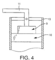
- a water faucet valve which includes a rotary member 9 which is connected to an operating knob 11 and which is slidably rotatably disposed on a stationary distributor member 10.
- the stationary distributor member 10 is fixed in a conduit 13, so as to divide the conduit into two sections.
- the rotary member 9 is disposed in one of the two sections of the conduit 13, and cooperates with the stationary distributor member 10 to selectively permit and inhibit a water flow between the two sections of the conduit 13.
- the rotary member 9 and the distributor member 10 have water communication apertures, so that the water flow through the two members 9, 10 is normally inhibited.
- the ceramic substrate of these sliding members 9, 10 is a dense alumina body which was prepared by firing a formed mass of a mixture consisting of powdered alumina and about 10% by weight of powdered silicate, at about 1600°C in air.
- the thus prepared sintered body includes crystal grains of alumina having a particle size of about 1-5 ⁇ m which are bonded together by silicate glass.
- the surface of the sintered alumina substrate which corresponds to the contacting surfaces of the rotary and stationary members 9, 10 was ground and smoothed by a paste of diamond. Then, the thus ground surface of the alumina substrate was subjected to chemical etching with an aqueous solution of hydrofluoric acid of 1% concentration, so that only the glass phase near the surface of the substrate was removed, and as a result the minute holes or pores 6 defined primarily by the alumina grains 2 were formed as shown in Fig. 3.
- the etching depth or the depth of the pores 6 was suitably adjusted within a range of 0.1-1 ⁇ m. This adjustment can be made by controlling the concentration of the hydrofluoric acid solution and the etching time.
- the alumina substrate whose surface has been mechanically ground and chemically etched was sufficiently washed with water and dried, and was then introduced into an evacuated electric furnace. While the interior of the furnace was held at about 900°C and at a reduced pressure, a predetermined amount of a silicone oil as the organosilicon compound was injected into the furnace, so that the intermediate film 7 including carbon and silicon was formed on the ground and etched surface of the alumina substrate, by pyrolysis of the silicone oil, as indicated in Fig. 3. In practice, a batch of alumina substrates subjected to the preliminary treatment described above was introduced into the furnace.
- the amount of the intermediate film 7 deposited on each alumina substrate is determined by the ratio of the injected amount of the silicone oil to the total mass of the alumina substrates introduced in the furnace. Generally, the amount of the intermediate film 7 is selected to be approximately equal to a half that of the pyrolytic carbon film 8 to be subsequently formed.
- the silicone oil was continuously injected into the furnace for about three minutes and then the interior of the furnace was kept at the predetermined pyrolyzing temperature for 15 minutes, during which the intermediate film 7 including carbon and silicon was formed from the product produced by the pyrolysis of the silicone oil, on the ground and etched surface of the alumina substrate.
- the furnace temperature was then raised up to 1050°C, and benzine was injected as hydrocarbon into the furnace, so as to be directed to the intermediate film 7, so that the pyrolytic carbon film 8 was formed on the intermediate film 7, by pyrolysis of benzine.
- benzine for the pyrolytic carbon film 8 was continuously injected into the furnace for about six minutes, in an amount twice as much as that of silicone oil injected for the intermediate film 7, so that the pyrolytic carbon film 8 formed had a thickness of about 0.3 ⁇ m.
- the pyrolytic carbon film 8 thus formed according to the present invention was electrically conductive.
- the present pyrolytic carbon film 8 had an increased degree of silver glossiness, and exhibited improved parallel orientation of the carbon crystallites 12, which contributes to a considerable increase in the strength and wear resistance.
- an alumina sliding member having the pyrolytic carbon film 8 formed on the intermediate film 7 was fabricated.
- the rotary member 9 was slidably rotated on the stationary distributor member 10, by repeated operation of the knob 11 in a cyclic manner.
- One cycle of sliding operation of the rotary member 9 or knob 11 consists of the following actions in the order of description: movement from hot-water stop position to hot-water delivery position; movement from the hot-water delivery position to cold-water stop position; movement from the cold-water stop position to cold-water delivery position; movement from the cold-water delivery position to the hot-water delivery position; and movement from the hot-water delivery position to the hot-water stop position.
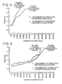
- the sliding resistance of the rotary and stationary members 9, 10 is represented by a torque necessary to rotate the rotary member 9 slidably on the stationary member 10.
- the torque values were measured at selected points of time during the cyclic sliding test, that is, when the number of sliding cycles reached selected values.
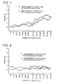
- the graphs of Figs. 5-8 indicate the torque values measured upon movements of the rotary member 9 to the hot-water delivery position and the cold-water delivery position, in relation to the number of the sliding cycles performed. The graphs show that the measured torque values generally increase with an increase in the number of the sliding cycles.
- the graph of Fig. 5 shows the test result of a comparative alumina sliding member (used as the members 9, 10) which is not provided with any wear-resistant film and is not lubricated with a grease.
- the graph of Fig. 6 shows the test result of a comparative alumina sliding member which is not provided with any wear-resistant film and is lubricated with a grease.
- the graph of Fig. 7 shows the test result of a comparative alumina sliding which is coated with a pyrolytic carbon film formed by pyrolysis on a surface of an alumina substrate which has been etched by hydrofluoric acid.
- the graph of Fig. 8 shows the test result of the alumina sliding member according to the present invention, which has the pyrolytic carbon film 8 formed on the intermediate film 7 formed on the alumina substrate surface by pyrolysis of an organosilicon compound as explained above in detail.
- the ceramic sliding member according to the principle of this invention is characterized by a double-layered structure consisting of the intermediate film which is formed by pyrolysis on the mechanically ground surface of the ceramic substrate and which includes carbon and silicon, and the pyrolytic carbon film which is formed on the intermediate film and which has a graphite-like layered structure.
- the pyrolytic carbon film which functions as the sliding surface of the sliding member is tightly secured through the intermediate film to the ceramic substrate which consists essentially of metal oxide and/or silicate.
- the provision of the intermediate film permits a high degree of parallelism of the planes of the pyrolytic carbon crystallites to the surface of the ceramic substrate surface.
- the pyrolytic carbon film which is comparatively economical to fabricate, is given an appreciably increased wear resistance owing to excellent orientation of the pyrolytic carbon crystallites.
- the present ceramic sliding member is capable of maintaining sufficiently low sliding resistance for a comparatively long period of use, without using an exclusive lubricant such as a grease, and without employing a relatively expensive wear-resistant material such as silicon carbide, amorphous diamond or diamond-like carbon (DLC) as used in the prior art.
- the present invention therefore has technical and industrial significance.
Landscapes
- Chemical & Material Sciences (AREA)
- Engineering & Computer Science (AREA)
- Ceramic Engineering (AREA)
- Materials Engineering (AREA)
- Organic Chemistry (AREA)
- Structural Engineering (AREA)
- General Chemical & Material Sciences (AREA)
- Chemical Kinetics & Catalysis (AREA)
- Mechanical Engineering (AREA)
- Metallurgy (AREA)
- Inorganic Chemistry (AREA)
- Sliding-Contact Bearings (AREA)
- Laminated Bodies (AREA)
- Chemical Vapour Deposition (AREA)
Applications Claiming Priority (3)
| Application Number | Priority Date | Filing Date | Title |
|---|---|---|---|
| JP34088094 | 1994-12-23 | ||
| JP34088094 | 1994-12-23 | ||
| JP340880/94 | 1994-12-23 |
Publications (3)
| Publication Number | Publication Date |
|---|---|
| EP0718256A2 EP0718256A2 (en) | 1996-06-26 |
| EP0718256A3 EP0718256A3 (en) | 1997-04-09 |
| EP0718256B1 true EP0718256B1 (en) | 1999-06-30 |
Family
ID=18341167
Family Applications (1)
| Application Number | Title | Priority Date | Filing Date |
|---|---|---|---|
| EP95309355A Expired - Lifetime EP0718256B1 (en) | 1994-12-23 | 1995-12-21 | Ceramic sliding member and process of fabricating the same |
Country Status (4)
| Country | Link |
|---|---|
| US (1) | US5763072A (es) |
| EP (1) | EP0718256B1 (es) |
| DE (1) | DE69510526T2 (es) |
| ES (1) | ES2135666T3 (es) |
Families Citing this family (14)
| Publication number | Priority date | Publication date | Assignee | Title |
|---|---|---|---|---|
| AU1523600A (en) | 1998-11-12 | 2000-05-29 | Nobel Biocare Ab | Diamond-like carbon coated dental instrument |
| ATE363870T1 (de) | 1999-04-15 | 2007-06-15 | Nobel Biocare Ab | Mit diamantähnlichem kohlenstoff überzogene zahnärztliche halterungschraube |
| US6547562B2 (en) | 2000-05-11 | 2003-04-15 | Nobel Biocare Ab | Pseudo-etching of diamond-like carbon coated instruments |
| DE10045339A1 (de) * | 2000-09-14 | 2002-04-04 | Wacker Chemie Gmbh | Mit Grafit beschichteter Formkörper aus gesintertem Siliciumcarbid |
| US8555921B2 (en) | 2002-12-18 | 2013-10-15 | Vapor Technologies Inc. | Faucet component with coating |
| US7866343B2 (en) * | 2002-12-18 | 2011-01-11 | Masco Corporation Of Indiana | Faucet |
| US6904935B2 (en) * | 2002-12-18 | 2005-06-14 | Masco Corporation Of Indiana | Valve component with multiple surface layers |
| US7866342B2 (en) | 2002-12-18 | 2011-01-11 | Vapor Technologies, Inc. | Valve component for faucet |
| US8220489B2 (en) | 2002-12-18 | 2012-07-17 | Vapor Technologies Inc. | Faucet with wear-resistant valve component |
| US20070207321A1 (en) * | 2004-03-30 | 2007-09-06 | Yoshinori Abe | Method For Treating Surface Of Material, Surface-Treated Material, Medical Material, And Medical Instrument |
| US20070026205A1 (en) | 2005-08-01 | 2007-02-01 | Vapor Technologies Inc. | Article having patterned decorative coating |
| DE102006018124A1 (de) * | 2006-04-19 | 2007-10-25 | Schwäbische Hüttenwerke Automotive GmbH & Co. KG | Verstellbare Rotationspumpe mit Verschleißminderung |
| EP2375111B1 (en) * | 2008-12-25 | 2015-10-21 | Kyocera Corporation | Sliding component and mechanical seal, faucet valve, and rolling support device equipped with same |
| DE102016200863B4 (de) | 2016-01-21 | 2021-12-16 | Gestra Ag | Kondensatableiter und Verfahren zum Ableiten von Kondensat |
Family Cites Families (6)
| Publication number | Priority date | Publication date | Assignee | Title |
|---|---|---|---|---|
| IT1182433B (it) * | 1985-02-12 | 1987-10-05 | Gevipi Ag | Organi di tenuta in materiale duro aventi basso coefficiente di attrito |
| US4647494A (en) * | 1985-10-31 | 1987-03-03 | International Business Machines Corporation | Silicon/carbon protection of metallic magnetic structures |
| DE3832692A1 (de) * | 1988-09-27 | 1990-03-29 | Leybold Ag | Dichtungselement mit einem absperrkoerper aus einem metallischen oder nichtmetallischen werkstoff und verfahren zum auftragen von hartstoffschichten auf den absperrkoerper |
| JPH03172683A (ja) * | 1989-11-30 | 1991-07-26 | Toto Ltd | セラミック製摺動部材 |
| JPH0441590A (ja) * | 1990-06-07 | 1992-02-12 | Nippon Cement Co Ltd | 摺動部材の製造方法 |
| JPH04165170A (ja) * | 1990-06-29 | 1992-06-10 | Tokyo Yogyo Co Ltd | 水栓バルブ部材 |
-
1995
- 1995-12-21 EP EP95309355A patent/EP0718256B1/en not_active Expired - Lifetime
- 1995-12-21 US US08/576,135 patent/US5763072A/en not_active Expired - Fee Related
- 1995-12-21 ES ES95309355T patent/ES2135666T3/es not_active Expired - Lifetime
- 1995-12-21 DE DE69510526T patent/DE69510526T2/de not_active Expired - Fee Related
Also Published As
| Publication number | Publication date |
|---|---|
| EP0718256A2 (en) | 1996-06-26 |
| DE69510526T2 (de) | 1999-12-30 |
| DE69510526D1 (de) | 1999-08-05 |
| EP0718256A3 (en) | 1997-04-09 |
| US5763072A (en) | 1998-06-09 |
| ES2135666T3 (es) | 1999-11-01 |
Similar Documents
| Publication | Publication Date | Title |
|---|---|---|
| EP0718256B1 (en) | Ceramic sliding member and process of fabricating the same | |
| US7216661B2 (en) | Method of forming a wear resistant component | |
| CN100526008C (zh) | 金刚石膜的抛光方法 | |
| US4979019A (en) | Printed circuit board with inorganic insulating matrix | |
| MX2008004339A (es) | Componente de valvula para grifo. | |
| AU3799393A (en) | Molybdenum enhanced low-temperature deposition of crystalline silicon nitride | |
| IE71921B1 (en) | Carbon-containing composite material part protected against oxidation and its production process | |
| BRPI1103920A2 (pt) | Torneira com componente de válvula resistente ao desgaste | |
| Fitzer et al. | Carbon, carbide and silicide coatings | |
| CN115259903B (zh) | 一种在基体材料上形成的高精度抗高温烧蚀涂层、其制备方法和包含该涂层的复合材料 | |
| JP2004175605A (ja) | 耐酸化性c/c複合材及びその製造方法 | |
| SE528133C2 (sv) | Underlag med en ciselerad yta för sintring av kroppar av metallpulver, keramik och liknande, användning av detta och förfarande för dess framställning | |
| CN108300967A (zh) | 耐高温低摩擦DLC/AlTiSiN多层复合涂层及其制备方法 | |
| JP3620910B2 (ja) | セラミックス製摺動部材の製造方法 | |
| TW202313523A (zh) | 製備塗覆基板的方法、塗覆基板及其用途 | |
| JP3764742B2 (ja) | 摺動装置及びフォーセットバルブ | |
| JP3431958B2 (ja) | 炭素繊維強化炭素材の耐酸化処理法 | |
| CN116904925B (zh) | 一种高温超润滑硅掺杂类金刚石碳膜及其制备方法与应用 | |
| KR100587584B1 (ko) | 탄화붕소가 코팅된 내마모성 부품 및 스퍼터링에 의한 그제조방법 | |
| JP3677392B2 (ja) | フォーセットバルブ | |
| JP3691090B2 (ja) | セラミック被覆炭素材及びその製造方法 | |
| CN116904925A (zh) | 一种高温超润滑硅掺杂类金刚石碳膜及其制备方法与应用 | |
| USRE34825E (en) | Composite article and method of making same | |
| JP2003171766A (ja) | 炭化珪素コーティング部材 | |
| JPH05306187A (ja) | 耐酸化性に優れた炭素繊維強化炭素材料 |
Legal Events
| Date | Code | Title | Description |
|---|---|---|---|
| PUAI | Public reference made under article 153(3) epc to a published international application that has entered the european phase |
Free format text: ORIGINAL CODE: 0009012 |
|
| 17P | Request for examination filed |
Effective date: 19960110 |
|
| AK | Designated contracting states |
Kind code of ref document: A2 Designated state(s): DE ES FR GB IT NL |
|
| RIN1 | Information on inventor provided before grant (corrected) |
Inventor name: MARUYAMA, KOJI Inventor name: LI, CHUNTING Inventor name: YAMAMOTO, ITSUKI Inventor name: KATO, ETSURO |
|
| PUAL | Search report despatched |
Free format text: ORIGINAL CODE: 0009013 |
|
| AK | Designated contracting states |
Kind code of ref document: A3 Designated state(s): DE ES FR GB IT NL |
|
| GRAG | Despatch of communication of intention to grant |
Free format text: ORIGINAL CODE: EPIDOS AGRA |
|
| 17Q | First examination report despatched |
Effective date: 19980731 |
|
| GRAG | Despatch of communication of intention to grant |
Free format text: ORIGINAL CODE: EPIDOS AGRA |
|
| GRAH | Despatch of communication of intention to grant a patent |
Free format text: ORIGINAL CODE: EPIDOS IGRA |
|
| GRAH | Despatch of communication of intention to grant a patent |
Free format text: ORIGINAL CODE: EPIDOS IGRA |
|
| GRAA | (expected) grant |
Free format text: ORIGINAL CODE: 0009210 |
|
| AK | Designated contracting states |
Kind code of ref document: B1 Designated state(s): DE ES FR GB IT NL |
|
| REF | Corresponds to: |
Ref document number: 69510526 Country of ref document: DE Date of ref document: 19990805 |
|
| ET | Fr: translation filed | ||
| ITF | It: translation for a ep patent filed |
Owner name: MODIANO & ASSOCIATI S.R.L. |
|
| REG | Reference to a national code |
Ref country code: ES Ref legal event code: FG2A Ref document number: 2135666 Country of ref document: ES Kind code of ref document: T3 |
|
| PLBE | No opposition filed within time limit |
Free format text: ORIGINAL CODE: 0009261 |
|
| STAA | Information on the status of an ep patent application or granted ep patent |
Free format text: STATUS: NO OPPOSITION FILED WITHIN TIME LIMIT |
|
| 26N | No opposition filed | ||
| REG | Reference to a national code |
Ref country code: GB Ref legal event code: IF02 |
|
| PGFP | Annual fee paid to national office [announced via postgrant information from national office to epo] |
Ref country code: GB Payment date: 20021211 Year of fee payment: 8 |
|
| PGFP | Annual fee paid to national office [announced via postgrant information from national office to epo] |
Ref country code: NL Payment date: 20021231 Year of fee payment: 8 |
|
| PG25 | Lapsed in a contracting state [announced via postgrant information from national office to epo] |
Ref country code: GB Free format text: LAPSE BECAUSE OF NON-PAYMENT OF DUE FEES Effective date: 20031221 |
|
| PG25 | Lapsed in a contracting state [announced via postgrant information from national office to epo] |
Ref country code: NL Free format text: LAPSE BECAUSE OF NON-PAYMENT OF DUE FEES Effective date: 20040701 |
|
| GBPC | Gb: european patent ceased through non-payment of renewal fee |
Effective date: 20031221 |
|
| NLV4 | Nl: lapsed or anulled due to non-payment of the annual fee |
Effective date: 20040701 |
|
| PGFP | Annual fee paid to national office [announced via postgrant information from national office to epo] |
Ref country code: FR Payment date: 20061025 Year of fee payment: 12 |
|
| PGFP | Annual fee paid to national office [announced via postgrant information from national office to epo] |
Ref country code: DE Payment date: 20061028 Year of fee payment: 12 |
|
| PGFP | Annual fee paid to national office [announced via postgrant information from national office to epo] |
Ref country code: IT Payment date: 20061231 Year of fee payment: 12 |
|
| PGFP | Annual fee paid to national office [announced via postgrant information from national office to epo] |
Ref country code: ES Payment date: 20070111 Year of fee payment: 12 |
|
| PG25 | Lapsed in a contracting state [announced via postgrant information from national office to epo] |
Ref country code: DE Free format text: LAPSE BECAUSE OF NON-PAYMENT OF DUE FEES Effective date: 20080701 |
|
| REG | Reference to a national code |
Ref country code: FR Ref legal event code: ST Effective date: 20081020 |
|
| REG | Reference to a national code |
Ref country code: ES Ref legal event code: FD2A Effective date: 20071222 |
|
| PG25 | Lapsed in a contracting state [announced via postgrant information from national office to epo] |
Ref country code: FR Free format text: LAPSE BECAUSE OF NON-PAYMENT OF DUE FEES Effective date: 20071231 Ref country code: ES Free format text: LAPSE BECAUSE OF NON-PAYMENT OF DUE FEES Effective date: 20071222 |
|
| PG25 | Lapsed in a contracting state [announced via postgrant information from national office to epo] |
Ref country code: IT Free format text: LAPSE BECAUSE OF NON-PAYMENT OF DUE FEES Effective date: 20071221 |