EP0718179B1 - Bearbeitungsanlage für Werkstücke - Google Patents
Bearbeitungsanlage für Werkstücke Download PDFInfo
- Publication number
- EP0718179B1 EP0718179B1 EP95120288A EP95120288A EP0718179B1 EP 0718179 B1 EP0718179 B1 EP 0718179B1 EP 95120288 A EP95120288 A EP 95120288A EP 95120288 A EP95120288 A EP 95120288A EP 0718179 B1 EP0718179 B1 EP 0718179B1
- Authority
- EP
- European Patent Office
- Prior art keywords
- ftf1
- driverless transport
- pushing
- ftf9
- work
- Prior art date
- Legal status (The legal status is an assumption and is not a legal conclusion. Google has not performed a legal analysis and makes no representation as to the accuracy of the status listed.)
- Expired - Lifetime
Links
- 238000003754 machining Methods 0.000 title description 5
- 238000009434 installation Methods 0.000 title 1
- 230000008878 coupling Effects 0.000 claims description 3
- 238000010168 coupling process Methods 0.000 claims description 3
- 238000005859 coupling reaction Methods 0.000 claims description 3
- 230000001939 inductive effect Effects 0.000 claims description 3
- 230000009471 action Effects 0.000 claims description 2
- 230000007246 mechanism Effects 0.000 claims description 2
- 230000001105 regulatory effect Effects 0.000 claims 2
- WABPQHHGFIMREM-UHFFFAOYSA-N lead(0) Chemical compound [Pb] WABPQHHGFIMREM-UHFFFAOYSA-N 0.000 claims 1
- 238000012545 processing Methods 0.000 description 34
- 238000004519 manufacturing process Methods 0.000 description 6
- 238000004891 communication Methods 0.000 description 3
- 239000000463 material Substances 0.000 description 3
- 241001136792 Alle Species 0.000 description 2
- 230000008859 change Effects 0.000 description 2
- 238000012546 transfer Methods 0.000 description 2
- 230000001133 acceleration Effects 0.000 description 1
- 238000010276 construction Methods 0.000 description 1
- 230000008030 elimination Effects 0.000 description 1
- 238000003379 elimination reaction Methods 0.000 description 1
- 239000002184 metal Substances 0.000 description 1
- 238000000034 method Methods 0.000 description 1
- 238000012986 modification Methods 0.000 description 1
- 230000004048 modification Effects 0.000 description 1
- NJPPVKZQTLUDBO-UHFFFAOYSA-N novaluron Chemical compound C1=C(Cl)C(OC(F)(F)C(OC(F)(F)F)F)=CC=C1NC(=O)NC(=O)C1=C(F)C=CC=C1F NJPPVKZQTLUDBO-UHFFFAOYSA-N 0.000 description 1
- 230000008569 process Effects 0.000 description 1
- 230000001960 triggered effect Effects 0.000 description 1
Images




Classifications
-
- B—PERFORMING OPERATIONS; TRANSPORTING
- B62—LAND VEHICLES FOR TRAVELLING OTHERWISE THAN ON RAILS
- B62D—MOTOR VEHICLES; TRAILERS
- B62D65/00—Designing, manufacturing, e.g. assembling, facilitating disassembly, or structurally modifying motor vehicles or trailers, not otherwise provided for
- B62D65/02—Joining sub-units or components to, or positioning sub-units or components with respect to, body shell or other sub-units or components
- B62D65/18—Transportation, conveyor or haulage systems specially adapted for motor vehicle or trailer assembly lines
-
- B—PERFORMING OPERATIONS; TRANSPORTING
- B60—VEHICLES IN GENERAL
- B60L—PROPULSION OF ELECTRICALLY-PROPELLED VEHICLES; SUPPLYING ELECTRIC POWER FOR AUXILIARY EQUIPMENT OF ELECTRICALLY-PROPELLED VEHICLES; ELECTRODYNAMIC BRAKE SYSTEMS FOR VEHICLES IN GENERAL; MAGNETIC SUSPENSION OR LEVITATION FOR VEHICLES; MONITORING OPERATING VARIABLES OF ELECTRICALLY-PROPELLED VEHICLES; ELECTRIC SAFETY DEVICES FOR ELECTRICALLY-PROPELLED VEHICLES
- B60L2200/00—Type of vehicles
- B60L2200/26—Rail vehicles
Definitions
- the invention relates to a processing system for workpieces, such as e.g. for car bodies according to the preamble of claim 1.
- DE 40 20 286 C2 describes a machining system for workpieces, such as Car bodies with a processing line known from a variety of processing platforms (Driverless transport vehicles) is formed, each with its own drive and have an associated control. They form in the processing line one push bandage gently adjacent and move in the other Areas continue to drive.
- Processing platforms Driverless transport vehicles
- EP 345 826 A2 describes a processing system for workpieces, such as Car bodies known that has at least one processing line by a variety of processing platforms (driverless transport vehicles) is formed, each have a self-propulsion and an associated control, which in the Processing lines form a pusher bandage and are located in the other areas move self-propelled.
- This system forms the preamble of claim 1.
- a disadvantage of the system is that the transport vehicles in the area of the processing line be put on a rail and controlled by a central control system are driven or braked on the outside. The own drive of the transport vehicles is switched off. This requires one for the assembly of the processing lines relatively high effort, because rails protrude into the floor or the floor must be installed, the change is relatively expensive. Also the cost for the external drive (acceleration drive for inserting the vehicle on Inlet, drive (pressure) for push assembly, brake drive (counter pressure) for Holding the pushing unit together and pull-out drive to pull off the Vehicle at the outlet) relatively high.
- the object of the invention is to provide the aforementioned device improve that the processing lines can be changed with little effort can.
- This object is achieved in that the driverless Transport vehicles also drive in the pushing unit without guide rails that the Driverless transport vehicles also in the pushing unit from their own drive motor are driven and that the driverless transport vehicles also in Shear bandages are controlled by their own controls.
- the transport platforms take up, carry, guide and determine their speed, waived can be.
- This provides a high degree of flexibility in the construction of the processing system reached. Because the well-known driverless transport vehicles in the fields are already self-propelled outside the processing lines, the effort is the vehicles to make it self-propelled even in the machining lines, not particularly high. So the previously known vehicles with only minor modifications can be used will.
- Embodiments of the invention are the subject of subclaims.
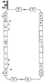
- FIG. 1 shows a processing system according to the invention with two processing lines, here from the driverless transport vehicles FTF1 to FTF9 and FTF14 to FTF22 are formed.
- the transport vehicles traveling in the processing lines FTF1 to FTF9 move together without gaps in a push group. This also applies to the FTF14 to FTF22 transport vehicles.
- the other transport vehicles FTF10 bis FTF13 and FTF23 to FTF26 are currently in inlet E or outlet A one Machining line or in the driving area between the two machining lines. In this Area, the vehicles drive themselves.
- the AGV rail-guided on a U-rail embedded in the floor or on auxiliary rollers guided, which scan the platform wall
- guided inductively guide wire
- FIG. 2 shows a cross section through a processing line.
- the height of the AGV is the height of the
- the platforms P provided here are adjusted so that the workers climb without steps must be able to move from the vehicle to the platform and vice versa.
- the AGV vehicle is controlled here by means of a guide wire LD embedded in the floor.
- the guidewire LD inductive tracking
- the vehicle draws its energy here two current collectors SA, which are attached to the AGV mobile and to two stationary at the Pedestal P attached SS busbars.
- the energy supplied can either used to charge the on-board battery (internal control) or directly to the traction motors supplied (external control).
- internal control internal control
- exital control traction motors supplied
- the vehicles are also driven by their own drive and own wheels - while in the state of the art the drive by stationary friction rollers on the pedestals.
- the direction of the vehicles AGV is also controlled not by forcing the platform, but only by the action of control pulses from the outside to the vehicle's own control system - so the vehicle also steers the wheels and is not supported by mechanical positive guides such as rails or Led vehicle edge.
- the direction can - as shown here - through inductive Forced guidance (guide wire LD), through a passive guide tape (one on the floor glued-on metal tape, the position of which is scanned by the AGV), the road boundary (It should be noted here that the sensors for the edge of the road are not on the Platform itself, but on the control mechanics of the AGV). Also possible are mechanical positive guides (like a rail), but also only on the steering mechanism of the AGV acts and not on the entire platform. Likewise can the guidance within the processing line is done through free navigation as it is also specified outside the processing lines. An exemplary navigation system for free navigation and guideless guidance of driverless industrial trucks is already known from EP 391 206 A. When using such a navigation system would then only be individual point-like navigation points in the processing line necessary along which the AGV travels.
- Each vehicle therefore has an on-board control system (on-board computer). Its tasks are: Communication in the stationary system control, user interface for the operator of the vehicle, determination of the destination for the vehicle, control of the load handling).
- FIG. 3 shows a possibility, such as a positive in the processing lines
- Shear bandage can be formed from several AGVs. This is done here e.g. thereby, that FTF2 is provided with a mechanical lock, here the pawl K, which in a corresponding recess of the preceding AGV1 engages and engages there.
- FIG. 4 shows a further possibility, such as the shear bandage within the processing lines can be formed.
- the FTF1 to FTF9 form their front sides are adapted in shape to the rear, again the pushing in the processing line, which is connected here by friction.
- the incoming AGV e.g. the two rear FTF8 and FTF9
- the FTF1 and FTF2 generate one Back pressure, which leads to a frictional hold of the shear bandage leads.
- the commands for increased forward driving, for normal driving (FTF3 to FTF7) or for braking (AGV1 and AGV2) from the central system control the respective vehicles are transferred.
- the commands can either be from of the stationary system control are given to the AGV or from the vehicle's own on-board control system which, based on its "local knowledge" of the system itself knows when the AGV has to unlock or withdraw.
- Figure 5 shows a possible speed control of the thrust assembly by a Regulation within each AGV itself.
- the reference variable speed is determined by the central system control ZA via a communication device to the AGV passed on and thus specified centrally. This is indicated by the lightning between the stationary communication device and the individual AGV.
- these AGVs are provided receivers that communicate the set speed to the controller R, which operates the actuator ST and information from the speedometer machine T about the actual speed receives.
- the actuator ST then controls the drive motor M and outputs the appropriate speed.
- the speed specification usually comes from the central system control ZA, since the operator can control the speed of the Pushing unit (e.g. by entering a production quantity per shift).
- This setpoint can also be changed, e.g. by the changed Production quantity or through the independent speed change through the central system control ZA, e.g. after a fire stop (catch-up).
- FIG. 6 Another speed control is shown with reference to FIG. 6.
- the Central system control ZA sends the setpoint to the central controller ZR.
- This processes the target information together with the actual information it receives from the central Tachometer machine ZT (here a stationary mounted measuring wheel) receives and gives the setpoint to the central controller ZST.
- This gives corresponding electrical impulses or values to the stationary busbar SS on which the mobile pantograph Access SA of the individual AGV1 to AGV26 of the processing line.
- the traction motors of the individual AGV1 to AGV26 on a common busbar SS switched.
- the drive motors of the individual AGVs are therefore central to the system-side control and actuating circuit with the appropriate energy for the desired Speed supplied.
- the speed characteristic proves itself here a series motor as particularly suitable.
- the main areas of application for the processing system according to the invention are Assembly lines intended for car bodies.
- the car body would then be on one AGV together with the responsible worker through the corresponding processing line drive.
- the worker would be on the pedestals remove the appropriate parts from the attached material boxes MB and add to the workpiece, here the body.
- Processing system in addition to assembly also in the manufacture of other components.
- passenger transport e.g. on Fairs or in museums, exhibitions or amusement parks.
- the train leads past exhibition objects.
- the Visitors get on the AGV at one point, ride a part and climb elsewhere from the AGV.
- the AGV can drive independently, either in association or driving alone.
Landscapes
- Engineering & Computer Science (AREA)
- Manufacturing & Machinery (AREA)
- Chemical & Material Sciences (AREA)
- Combustion & Propulsion (AREA)
- Transportation (AREA)
- Mechanical Engineering (AREA)
- Control Of Position, Course, Altitude, Or Attitude Of Moving Bodies (AREA)
Description
- Fig. 1
- eine Bearbeitungsanlage im Schubverband in Draufsicht,
- Fig. 2
- einen Schnitt durch eine Bearbeitungslinie 90° zur Fahrtrichtung,
- Fig. 3
- ein Detail einer mechanischen Verriegelung zweier FTF,
- Fig. 4
- eine andere Möglichkeit der Bildung des Schubverbands,
- Fig. 5+6
- zwei verschiedene Steuervarianten für die Geschwindigkeit in der Bearbeitungslinie.
- alle Arbeitsfließlinien, bei denen der Werker auf dem FTF mitfahrend an bereitgestellten Teilen vorbeifährt (z.B. Karossenmontage, Motorenfertigung, Achsfertigung, Kompressorfertigung usw.)
- alle Arbeitsfließlinien, bei denen nur das Werkstück fährt und am stationären Arbeitsplatz vorbeikommt (typisches Fließband). In diesem Fall fährt der Werker nicht mit auf dem FTF sondern steht am "Band" oder läuft ein Stück mit (z.B. Kühlschrankmontage).
- Kommissionieranlage. Das FTF ist dann das Kommissionierfahrzeug, auf das die zu kommissionierenden Teile aufgelegt werden, die entlang dem Schubverband als Bereitstellungszone gelagert sind. Danach fährt das FTF zu einem Einzel-Arbeitsplatz, wo die vorher kommissionierten Einzelteile zusammengebaut werden.
- Sortieranlage. Das FTF ist dann das Sortierfahrzeug, auf das die zu sortierenden Teile aufgelegt werden (z.B. große Pakete, Koffer, Behälter unterschiedlicher Größe und Form). An der richtigen Stelle werden dann die Teile vom FTF genommen oder geschoben.
Claims (6)
- Bearbeitungsanlage für Werkstücke (W), wie z.B. PKW-Karossen, mit mindestens einer Bearbeitungslinie, die von einer Vielzahl von Bearbeitungsplattformen (fahrerlosen Transportfahrzeugen FTF1 bis FTF26) gebildet wird, die je einen Eigenantrieb und eine dazugehörige Steuerung haben, die in den Bearbeitungslinien einen Schubverband bilden und die sich in den anderen Bereichen selbstfahrend fortbewegen, dadurch gekennzeichnet, daß die fahrerlosen Transportfahrzeuge (FTF1 bis FTF9) auch im Schubverband ohne Führungsschienen fahren, daß die fahrerlosen Transportfahrzeuge (FTF1 bis FTF9) auch im Schubverband von ihrem eigenen Fahrmotor (M) angetrieben werden und daß die fahrerlosen Transportfahrzeuge (FTF1 bis FTF9) auch im Schubverband von ihrer eigenen Steuerung (R, ST, T, M) gesteuert werden.
- Bearbeitungsanlage nach Anspruch 1, dadurch gekennzeichnet, daß die fahrerlosen Transportfahrzeuge (FTF1 bis FTF9) im Schubverband mittels mechanischer Elemente (Verriegelung, Klinke K, Kupplung) formschlüssig miteinander verbunden sind.
- Bearbeitungsanlage nach Anspruch 1, dadurch gekennzeichnet, daß die fahrerlosen Transportfahrzeug (FTF1 bis FTF9) im Schubverband kraftschlüssig durch Schieben des oder der hinteren (FTF8, FTF9) und Bremsen des oder der vorderen fahrerlosen Transportfahrzeuge (FTF1, FTF2) miteinander verbunden sind.
- Bearbeitungsanlage nach einem der Ansprüche 1 bis 3, dadurch gekennzeichnet, daß die Geschwindigkeit des Schubverbandes durch separate Regelung (Regler R, Steller ST, Tachomaschine T, Motor M) innerhalb jedes einzelnen FTF geregelt wird.
- Bearbeitungsanlage nach einem der Ansprüche 1 bis 3, dadurch gekennzeichnet, daß die Geschwindigkeit des Schubverbandes durch zentrale Ansteuerung (ZA, ZST, ZR, ZT) aller beteiligten FTF geregelt wird.
- Bearbeitungsanlage nach einem der vorhergehenden Ansprüche, dadurch gekennzeichnet, daß die Richtungsvorgabe im Schubverband durch Einwirkung auf die Lenkmechanik des FTF durch induktive Zwangsführung (Leitdraht LD), ein passives Leitband, die Fahrbahnrandbegrenzung, durch eine mechanische Zwangsführung (Schiene) oder durch freie Navigation erfolgt.
Applications Claiming Priority (2)
| Application Number | Priority Date | Filing Date | Title |
|---|---|---|---|
| DE4446420A DE4446420A1 (de) | 1994-12-23 | 1994-12-23 | Bearbeitungsanlage für Werkstücke |
| DE4446420 | 1994-12-23 |
Publications (2)
| Publication Number | Publication Date |
|---|---|
| EP0718179A1 EP0718179A1 (de) | 1996-06-26 |
| EP0718179B1 true EP0718179B1 (de) | 1998-05-20 |
Family
ID=6536992
Family Applications (1)
| Application Number | Title | Priority Date | Filing Date |
|---|---|---|---|
| EP95120288A Expired - Lifetime EP0718179B1 (de) | 1994-12-23 | 1995-12-21 | Bearbeitungsanlage für Werkstücke |
Country Status (3)
| Country | Link |
|---|---|
| EP (1) | EP0718179B1 (de) |
| DE (2) | DE4446420A1 (de) |
| ES (1) | ES2116033T3 (de) |
Families Citing this family (18)
| Publication number | Priority date | Publication date | Assignee | Title |
|---|---|---|---|---|
| DE10231504B4 (de) * | 2002-07-12 | 2006-09-07 | Eisenmann Maschinenbau Gmbh & Co. Kg | Beschichtungsanlage mit einem Skidfördersystem |
| EP1352817A1 (de) * | 2003-05-13 | 2003-10-15 | TMS Automotion GmbH | Transporteinrichtung und Verfahren zum Transport von Bauteilen |
| DE10344528A1 (de) * | 2003-09-25 | 2005-04-28 | Volkswagen Ag | Verfahren zur Prüfung und/oder Einstellung eines fertig montierten Fahrzeuges |
| JP4730310B2 (ja) * | 2004-12-24 | 2011-07-20 | アイシン・エィ・ダブリュ株式会社 | セル生産方法及びセル生産設備 |
| DE102005034582B4 (de) * | 2005-07-25 | 2007-11-08 | Eisenmann Anlagenbau Gmbh & Co. Kg | Fördersystem und Verfahren zum gleichzeitigen Transport von Werkstücken und Monteuren in einer Fertigungslinie |
| DE102006025545A1 (de) * | 2006-06-01 | 2007-12-06 | Eisenmann Anlagenbau Gmbh & Co. Kg | Fahrerloses Transportsystem |
| DE102006059886A1 (de) * | 2006-12-19 | 2008-06-26 | Emil Schmid Maschinen- und Apparatebau GmbH & Co. KG. | Transportsystem für Baugruppen mit in einem geschlossenen Kreislauf umlaufenden, begehbaren Montageplattformen |
| DE102010006653B4 (de) * | 2010-02-03 | 2014-10-30 | Audi Ag | Verfahren und Vorrichtung zum Wechseln der Materialwagen eines insbesondere fahrerlosen Transportsystems |
| CN101823520B (zh) * | 2010-05-17 | 2011-06-29 | 华中科技大学 | 一种轮辐状车身自动排序缓冲区及其排序方法 |
| MX352690B (es) * | 2012-05-11 | 2017-12-04 | Honda Motor Co Ltd | Sistema de montaje de un componente en la carrocería del vehículo. |
| DE102015205032A1 (de) | 2015-03-19 | 2016-09-22 | Kuka Roboter Gmbh | Fahrzeugverbund und Verfahren zum Bilden und Betreiben eines Fahrzeugverbundes |
| DE102017103931A1 (de) | 2017-02-24 | 2018-08-30 | Eisenmann Se | Fördersystem und Verfahren zum gleichzeitigen Transport von Werkstücken und Werkern |
| DE102017108023A1 (de) * | 2017-04-13 | 2018-10-18 | Eisenmann Se | Verfahren und Fördersystem zum gleichzeitigen Transport von langgestreckten Werkstücken und Werkern in einer Fertigungslinie |
| DE102017113343A1 (de) | 2017-06-19 | 2018-12-20 | Eisenmann Se | Verfahren und Fertigungsanlage zur Herstellung von Fahrzeugen und Oberflächenbehandlungsanlage zur Oberflächenbehandlung von Fahrzeugkarosserien |
| DE102019117036A1 (de) | 2019-06-25 | 2020-12-31 | Eisenmann Se | Freifahrender Transportwagen und Fördersystem zum Fördern sowie Behandlungsanlage zum Behandeln von Werkstücken |
| DE102019131307A1 (de) * | 2019-11-20 | 2021-05-20 | Eisenmann Se | Förderanlage zum Fördern von Werkstücken, Fertigungsanlage mit einer solchen Förderanlage und Verfahren zum Fertigen von Werkstücken |
| DE102022111317A1 (de) | 2022-05-06 | 2023-11-09 | Dürr Systems Ag | Montagesystem mit einer Arbeitsplatzbox und einem Transportfahrzeug sowie Verfahren zum Transfer eines Werkobjekts zwischen einem Transportfahrzeug und einer Arbeitsplatzbox |
| DE102023111504A1 (de) * | 2023-05-03 | 2024-11-07 | Fft Produktionssysteme Gmbh & Co. Kg | Begehbare Montagestation, insbesondere Montageplattform, und Verfahren zu deren Betrieb |
Family Cites Families (1)
| Publication number | Priority date | Publication date | Assignee | Title |
|---|---|---|---|---|
| GB2208499B (en) * | 1987-04-01 | 1991-07-10 | Litton Uk Ltd | Vehicle assembly line having an automated guided vehicle system |
-
1994
- 1994-12-23 DE DE4446420A patent/DE4446420A1/de not_active Withdrawn
-
1995
- 1995-12-21 DE DE59502249T patent/DE59502249D1/de not_active Expired - Fee Related
- 1995-12-21 ES ES95120288T patent/ES2116033T3/es not_active Expired - Lifetime
- 1995-12-21 EP EP95120288A patent/EP0718179B1/de not_active Expired - Lifetime
Also Published As
| Publication number | Publication date |
|---|---|
| EP0718179A1 (de) | 1996-06-26 |
| ES2116033T3 (es) | 1998-07-01 |
| DE4446420A1 (de) | 1996-06-27 |
| DE59502249D1 (de) | 1998-06-25 |
Similar Documents
| Publication | Publication Date | Title |
|---|---|---|
| EP0718179A1 (de) | Bearbeitungsanlage für Werkstücke | |
| DE10142395C5 (de) | Lager- und Transportsystem in modularer Bauweise | |
| DE2324393B2 (de) | Anlage zur Montage von Kraftfahrzeugen oder Teilen eines Kraftfahrzeuges | |
| DE2621021A1 (de) | Anlage und einrichtung zur automatischen handhabung von handwagen, insbesondere von krankenhauswagen | |
| DE102017103931A1 (de) | Fördersystem und Verfahren zum gleichzeitigen Transport von Werkstücken und Werkern | |
| DE102010015054A1 (de) | Lager- und Transportsystem für Transportbehälter od. dgl. | |
| DE102017012077A1 (de) | Transportsystem mit selbstfahrenden Werkstückwagen | |
| AT405270B (de) | Seilbahnanlage | |
| EP0635414B1 (de) | Hänge-Fördersystem | |
| DE102015113177A1 (de) | Halte- und Wechselstation für Kabinenfahrzeuge eines schienengebundenen Personenverkehrssystems | |
| EP0711696A1 (de) | Garage für die Fahrzeuge einer Umlaufseilbahn | |
| EP1175362B1 (de) | Transportsystem | |
| DE4119998A1 (de) | Lagersystem | |
| DE3443827A1 (de) | Elektrische zugbahnanlage | |
| AT408537B (de) | Verfahren zum betrieb einer anlage zum transport von personen und bzw. oder von gütern | |
| DE69402859T2 (de) | Transportvorrichtung und verfahren zum transportieren von containern | |
| DD251328A5 (de) | Selbstfahrender wagen | |
| EP0698685A1 (de) | Verfahren und Vorrichtung zum lagegenauen Einbringen von Befestigungsmitteln in Anschlusskörper einer Tragkonstruktion von Fahrwegen für spurgebundene Transportsysteme, insbesondere Magnetschwebebahnen | |
| DE3318469A1 (de) | Mehrspuriges schienensystem | |
| DE212006000027U1 (de) | Beförderungssystem in Form einer Hängebahn für Personen, insbesondere zu Vergnügungszwecken, oder für Güter | |
| DE202015104196U1 (de) | Halte- und Wechselstation für Kabinenfahrzeuge eines schienengebundenen Personenverkehrssystems | |
| EP0677435A2 (de) | Laufwagen zum Transport von Werkstücken | |
| DE202019103340U1 (de) | Einrichtung zum Transport von mindestens einem Fahrgast | |
| DE19902398C2 (de) | Elektrohängebahn | |
| DE202005011269U1 (de) | Flexibles Gleistransportsystem |
Legal Events
| Date | Code | Title | Description |
|---|---|---|---|
| PUAI | Public reference made under article 153(3) epc to a published international application that has entered the european phase |
Free format text: ORIGINAL CODE: 0009012 |
|
| AK | Designated contracting states |
Kind code of ref document: A1 Designated state(s): BE DE ES FR GB IT SE |
|
| 17P | Request for examination filed |
Effective date: 19960522 |
|
| 17Q | First examination report despatched |
Effective date: 19970417 |
|
| GRAG | Despatch of communication of intention to grant |
Free format text: ORIGINAL CODE: EPIDOS AGRA |
|
| GRAG | Despatch of communication of intention to grant |
Free format text: ORIGINAL CODE: EPIDOS AGRA |
|
| GRAH | Despatch of communication of intention to grant a patent |
Free format text: ORIGINAL CODE: EPIDOS IGRA |
|
| GRAH | Despatch of communication of intention to grant a patent |
Free format text: ORIGINAL CODE: EPIDOS IGRA |
|
| GRAA | (expected) grant |
Free format text: ORIGINAL CODE: 0009210 |
|
| AK | Designated contracting states |
Kind code of ref document: B1 Designated state(s): BE DE ES FR GB IT SE |
|
| ITF | It: translation for a ep patent filed | ||
| ET | Fr: translation filed | ||
| REF | Corresponds to: |
Ref document number: 59502249 Country of ref document: DE Date of ref document: 19980625 |
|
| REG | Reference to a national code |
Ref country code: ES Ref legal event code: FG2A Ref document number: 2116033 Country of ref document: ES Kind code of ref document: T3 |
|
| GBT | Gb: translation of ep patent filed (gb section 77(6)(a)/1977) |
Effective date: 19980619 |
|
| PG25 | Lapsed in a contracting state [announced via postgrant information from national office to epo] |
Ref country code: SE Free format text: LAPSE BECAUSE OF FAILURE TO SUBMIT A TRANSLATION OF THE DESCRIPTION OR TO PAY THE FEE WITHIN THE PRESCRIBED TIME-LIMIT Effective date: 19980820 |
|
| PGFP | Annual fee paid to national office [announced via postgrant information from national office to epo] |
Ref country code: FR Payment date: 19981209 Year of fee payment: 4 |
|
| PGFP | Annual fee paid to national office [announced via postgrant information from national office to epo] |
Ref country code: BE Payment date: 19990215 Year of fee payment: 4 |
|
| PLBE | No opposition filed within time limit |
Free format text: ORIGINAL CODE: 0009261 |
|
| STAA | Information on the status of an ep patent application or granted ep patent |
Free format text: STATUS: NO OPPOSITION FILED WITHIN TIME LIMIT |
|
| 26N | No opposition filed | ||
| PG25 | Lapsed in a contracting state [announced via postgrant information from national office to epo] |
Ref country code: GB Free format text: LAPSE BECAUSE OF NON-PAYMENT OF DUE FEES Effective date: 19991221 |
|
| PG25 | Lapsed in a contracting state [announced via postgrant information from national office to epo] |
Ref country code: ES Free format text: LAPSE BECAUSE OF NON-PAYMENT OF DUE FEES Effective date: 19991222 |
|
| PG25 | Lapsed in a contracting state [announced via postgrant information from national office to epo] |
Ref country code: BE Free format text: LAPSE BECAUSE OF NON-PAYMENT OF DUE FEES Effective date: 19991231 |
|
| BERE | Be: lapsed |
Owner name: INDUMAT G.M.B.H. & CO. K.G. TRANSPORT- UND LAGERS Effective date: 19991231 |
|
| GBPC | Gb: european patent ceased through non-payment of renewal fee |
Effective date: 19991221 |
|
| PG25 | Lapsed in a contracting state [announced via postgrant information from national office to epo] |
Ref country code: FR Free format text: LAPSE BECAUSE OF NON-PAYMENT OF DUE FEES Effective date: 20000831 |
|
| REG | Reference to a national code |
Ref country code: FR Ref legal event code: ST |
|
| PGFP | Annual fee paid to national office [announced via postgrant information from national office to epo] |
Ref country code: DE Payment date: 20040224 Year of fee payment: 9 |
|
| REG | Reference to a national code |
Ref country code: ES Ref legal event code: FD2A Effective date: 20000114 |
|
| PG25 | Lapsed in a contracting state [announced via postgrant information from national office to epo] |
Ref country code: DE Free format text: LAPSE BECAUSE OF NON-PAYMENT OF DUE FEES Effective date: 20050701 |
|
| PG25 | Lapsed in a contracting state [announced via postgrant information from national office to epo] |
Ref country code: IT Free format text: LAPSE BECAUSE OF NON-PAYMENT OF DUE FEES;WARNING: LAPSES OF ITALIAN PATENTS WITH EFFECTIVE DATE BEFORE 2007 MAY HAVE OCCURRED AT ANY TIME BEFORE 2007. THE CORRECT EFFECTIVE DATE MAY BE DIFFERENT FROM THE ONE RECORDED. Effective date: 20051221 |