EP0718092A1 - Münzprägepresse - Google Patents
Münzprägepresse Download PDFInfo
- Publication number
- EP0718092A1 EP0718092A1 EP95119430A EP95119430A EP0718092A1 EP 0718092 A1 EP0718092 A1 EP 0718092A1 EP 95119430 A EP95119430 A EP 95119430A EP 95119430 A EP95119430 A EP 95119430A EP 0718092 A1 EP0718092 A1 EP 0718092A1
- Authority
- EP
- European Patent Office
- Prior art keywords
- embossing
- coin
- pressure plate
- articulated
- drive
- Prior art date
- Legal status (The legal status is an assumption and is not a legal conclusion. Google has not performed a legal analysis and makes no representation as to the accuracy of the status listed.)
- Granted
Links
Images


Classifications
-
- B—PERFORMING OPERATIONS; TRANSPORTING
- B30—PRESSES
- B30B—PRESSES IN GENERAL
- B30B1/00—Presses, using a press ram, characterised by the features of the drive therefor, pressure being transmitted directly, or through simple thrust or tension members only, to the press ram or platen
- B30B1/10—Presses, using a press ram, characterised by the features of the drive therefor, pressure being transmitted directly, or through simple thrust or tension members only, to the press ram or platen by toggle mechanism
- B30B1/14—Presses, using a press ram, characterised by the features of the drive therefor, pressure being transmitted directly, or through simple thrust or tension members only, to the press ram or platen by toggle mechanism operated by cams, eccentrics, or cranks
-
- B—PERFORMING OPERATIONS; TRANSPORTING
- B30—PRESSES
- B30B—PRESSES IN GENERAL
- B30B1/00—Presses, using a press ram, characterised by the features of the drive therefor, pressure being transmitted directly, or through simple thrust or tension members only, to the press ram or platen
- B30B1/10—Presses, using a press ram, characterised by the features of the drive therefor, pressure being transmitted directly, or through simple thrust or tension members only, to the press ram or platen by toggle mechanism
- B30B1/106—Presses, using a press ram, characterised by the features of the drive therefor, pressure being transmitted directly, or through simple thrust or tension members only, to the press ram or platen by toggle mechanism operated by another toggle mechanism
-
- B—PERFORMING OPERATIONS; TRANSPORTING
- B44—DECORATIVE ARTS
- B44B—MACHINES, APPARATUS OR TOOLS FOR ARTISTIC WORK, e.g. FOR SCULPTURING, GUILLOCHING, CARVING, BRANDING, INLAYING
- B44B5/00—Machines or apparatus for embossing decorations or marks, e.g. embossing coins
- B44B5/0052—Machines or apparatus for embossing decorations or marks, e.g. embossing coins by pressing
- B44B5/0057—Machines or apparatus for embossing decorations or marks, e.g. embossing coins by pressing using more than one die assembly simultaneously
Definitions
- the invention relates to a coin press, with a machine frame, an embossing drive for plunger and embossing die, an ejector embossing die, against which the embossing die can be pressed with the interposition of the embossing blank and to which part is yieldable, a drive for the ejector movement of the ejector embossing die and a device for feeding the Embossing blank and for removing the finished part.
- Such a coin stamping press is known from EP-A-0 101 590.
- the embossing drive takes place by means of a triangular lever known per se, driven by a crankshaft via a central bearing, which is articulated with its rear rocker arm bearing on a handlebar and via this on the frame side and with its front rocker arm bearing via a push rod on the tappet.
- This oscillation system is designed such that pivot points and articulation points in their positions relative to one another enable a circular movement which is at least approximated for the push rod in its pivot point on the tappet at the time it passes through the rear dead center.
- the arrangement mentioned makes it possible to control the linear movement of the plunger in such a way that there is sufficient time to remove a minted coin from the minting tool between two minting processes and to insert a new coin blank.
- a disadvantage of the known coin minting press is that the described embossing drive takes up a relatively large amount of space, especially when it is to be used in presses which pressures of more than 200 t should exert on the coin blank. Since these forces also act on the embossing drive, the individual components of the same must be appropriately dimensioned so that the individual components must be relatively large.
- the present invention is therefore based on the object of eliminating the present disadvantages of the prior art, in particular providing a coin embossing press which has the smallest possible height and less play within the embossing drive.
- Another advantage of the coin embossing press according to the invention is the reduction in the play of the embossing drive, since it has significantly fewer joints than is the case with known coin embossing presses, so that the overall game, which is composed of the game in the individual joints, is reduced . This reduction in play is particularly noticeable with frequent load changes, as is the case with fast-running coin minting presses.
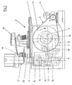
- a shaft 3 is provided in the machine frame 1 of a coin press 2, which is driven by a motor 6 via a flywheel 4 and a belt transmission 5.
- a double cam 7 is placed, which is part of a cam mechanism 8.
- the cam mechanism 8 also has a rocker arm 9, which is provided with two arms, on each of which a cam roller 10 is attached, the cam rollers 10 abutting the double cam disc 7 and scanning them.
- the rocker arm 9 is connected in an articulated manner to a knee joint transmission 12 via a pressure plate 11.
- the knee joint transmission 12 has an upper pressure plate 13 and a lower pressure plate 14, which are connected to one another at one point and are articulated together with the pressure plate 11.
- the upper pressure plate 13 is articulated at one end to the plunger 15 of the minting press 2, the plunger 15 being linearly displaceable in a suitable plunger guide 16.
- the other end of the lower pressure plate 14 is articulated to the machine frame 1.
- the plunger in turn is connected to a plunger tool 17 arranged above the plunger 15, into which the coin blanks are inserted from a feed drum 18 via a feed station 19 into a turret plate 20, which is provided with a stepping gear mechanism.
- An upper tool 21 is provided above the plunger tool 17 for simultaneously embossing the front and back of the coin.
- FIGS. 2 to 4 show in an enlarged representation the combination of the cam mechanism 8 and the knee joint mechanism 12 already described in connection with FIG. 1.
- rocker arm 9 has at its end facing the knee joint mechanism 8 a further bolt 23, wherein the pressure bracket 11 is articulated on the bolt 23, which, as already mentioned, establishes a connection to the knee joint mechanism 12.
- Both the side of the pressure plate 11 facing away from the cam mechanism 8 and also one end of the upper pressure plate 13 and the lower pressure plate 14 are connected to one another in an articulated manner on a bolt 24.
- a tool clamping 27 for an embossing die 28 is provided on the plunger 15.
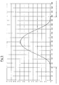
- plunger 15 moves in accordance with the movement diagram shown in FIG. 5.
- the tappet 15 carries out an embossing stroke in a range from approximately 60 ° crank angle to 300 ° crank angle.
- the plunger 15 is not raised at all, so that the plunger 15 also during this time all the tools attached to it stand still and during this time a new coin blank can be brought into the minting station of the coin embossing press by the feed drum 18, the feed station 19 and the turret plate 20 (see FIG. 1). A new stamping process can then take place.
- FIG 6 schematically shows an overall view of the gear combination used comprising the cam mechanism 8 and the knee joint mechanism 12.
- the dash-dotted lines illustrate the deflected position of the knee joint mechanism 8.
- the double cam disc is graphically divided into three areas, with the solid line showing the movement of the plunger 15 upwards, i.e. when an embossing stroke is carried out, while the dashed line symbolizes the movement of the plunger 15 downwards, i.e. the return stroke, and where the dash-dotted line represents the area in which the plunger 15 maintains its position, ie the area in which a minted coin is removed and a new coin blank is inserted into the minting tool.
- the overall height of the entire coin press 2 can be significantly reduced in a simple manner.
- the arrangement described has the advantage that in the main power flow of the embossing drive, that is, from the machine frame 1 via the Bolt 24 through the knee joint gear 12 to the plunger 15, compared to the prior art, significantly fewer articulation points are contained, so that a better power transmission is possible.
- the arrangement described can, for example, reduce the working height of the minting press at a pressure of 300 t from approximately 1900 mm to approximately 1400 mm.
Landscapes
- Engineering & Computer Science (AREA)
- Mechanical Engineering (AREA)
- Forging (AREA)
- Adornments (AREA)
- Transmission Devices (AREA)
- Shaping Metal By Deep-Drawing, Or The Like (AREA)
Abstract
Description
- Die Erfindung betrifft eine Münzprägepresse, mit einem Maschinengestell, einem Prägeantrieb für Stößel und Prägestempel, einem Auswerferprägestempel, gegen den der Prägestempel unter Zwischenlage des Prägerohlings preßbar und hierzu zum Teil nachgebbar ist, einem Antrieb für die Auswerferbewegung des Auswerferprägestempels und je einer Einrichtung zum Zuführen des Prägerohlings und zum Abführen des Prägefertigteiles.
- Eine derartige Münzprägepresse ist aus der EP-A-0 101 590 bekannt. Bei der in der genannten Druckschrift offenbarten Münzprägepresse erfolgt der Prägeantrieb mittels eines ansich bekannten, von einer Kurbelwelle über ein Mittellager getriebenen Dreieckhebels, welcher mit seinem hinteren Schwingenlager an einem Lenker und über diesen gestellseitig und mit seinem vorderen Schwingenlager über eine Druckstange am Stößel angelenkt ist. Dieses Schwingsystem ist so ausgebildet, daß Dreh- und Anlenkpunkte in ihren Lagen zueinander eine für die Druckstange in ihrem Drehpunkt am Stößel zum Zeitpunkt dessen Durchfahrens des hinteren Totpunktes zumindest angenäherte kreisförmige Bewegung ermöglichen.
- Durch die genannte Anordnung ist es möglich, die Linearbewegung des Stößels so zu steuern, daß ausreichend Zeit verbleibt, um zwischen zwei Prägevorgängen eine geprägte Münze aus dem Prägewerkzeug zu entnehmen und einen neuen Münzrohling einzulegen.
- Nachteilig an der bekannten Münzprägepresse ist jedoch, daß der beschriebene Prägeantrieb verhältnismäßig viel Raum beansprucht, insbesondere wenn er in Pressen eingesetzt werden soll, welche Drücke von mehr als 200 t auf den Münzrohling ausüben sollen. Da diese Kräfte auch auf den Prägeantrieb einwirken, müssen die einzelnen Bauteile desselben entsprechend stabil dimensioniert werden, so daß die einzelnen Bauteile relativ groß vorgesehen werden müssen.
- Ein weiterer Nachteil der bekannten Münzprägepresse ist das relativ große Spiel innerhalb des Prägeantriebs, das aus der Vielzahl der eingesetzten Gelenke resultiert.
- Der vorliegenden Erfindung liegt daher die Aufgabe zugrunde, die vorliegenden Nachteile des Standes der Technik zu beseitigen, insbesondere eine Münzprägepresse vorzusehen, welche eine möglichst geringe Bauhöhe und ein geringeres Spiel innerhalb des Prägeantriebes aufweist.
- Erfindungsgemäß wird diese Aufgabe durch die im kennzeichnenden Teil des Patentanspruchs genannten Merkmale gelöst.
- Durch das Vorsehen eines Kurvengetriebes, das von einem Schwinghebel mit Kurvenrollen abgetastet wird, kann auf einfache Art und Weise ein Kniegelenkgetriebe angesteuert werden, welches gegenüber dem Kniegelenkgetriebe des Standes der Technik eine wesentlich geringere Bauhöhe aufweist, da der beim Stand der Technik verwendete Dreieckhebel entfällt, so daß der gesamte Prägeantrieb und somit auch die Münzprägepresse ansich eine geringere Bauhöhe aufweist.
- Ein weiterer Vorteil der erfindungsgemäßen Münzprägepresse liegt in der Reduzierung des Spieles des Prägeantriebes, da dieser wesentlich weniger Gelenke aufweist, als dies bei bekannten Münzprägepressen der Fall ist, so daß sich das Gesamtspiel, welches sich aus dem Spiel in den einzelnen Gelenken zusammensetzt, reduziert wird. Diese Spielreduzierung macht sich insbesondere bei häufigen Lastwechseln, wie dies bei schnell laufenden Münzprägepresen der Fall ist, positiv bemerkbar.
- Vorteilhafte Ausgestaltungen und Weiterbildungen der Erfindung ergeben sich aus dem nachfolgend anhand der Zeichnung prinzipmäßig beschriebenen Ausführungsbeispiel.
- Es zeigt:
- Fig. 1
- schematisch eine Seitenansicht einer erfindungsgemäßen Münzprägepresse,
- Fig. 2
- in vergrößerter Darstellung den Prägeantrieb für die Münzprägepresse der Fig. 1,
- Fig. 3
- einen Schnitt entlang der Linie III-III der Fig. 2,
- Fig. 4
- einen Schnitt entlang der Linie IV-IV der Fig. 2,
- Fig. 5
- ein Diagramm, in welchem der Weg des Prägestempels der Münzprägepresse nach der Fig. 1 über dem Kurbelwinkel der Exzenterwelle abgetragen ist, und
- Fig. 6
- schematisch eine Gesamtansicht der verwendeten Getriebekombination.
- Bezugnehmend auf Fig. 1 ist in dem Maschinengestell 1 einer Münzprägepresse 2 eine Welle 3 vorgesehen, welche über ein Schwungrad 4 und ein Riemengetriebe 5 von einem Motor 6 angetrieben ist.
- Auf die Welle 3 ist eine Doppelkurvenscheibe 7 aufgesetzt, welche Teil eines Kurvengetriebes 8 ist.
- Das Kurvengetriebe 8 weist des weiteren einen Schwinghebel 9 auf, welcher mit zwei Armen versehen ist, an denen jeweils eine Kurvenrolle 10 angebracht ist, wobei die Kurvenrollen 10 an der Doppelkurvenscheibe 7 anliegen und diese abtasten.
- Der Schwinghebel 9 ist über eine Drucklasche 11 mit einem Kniegelenkgetriebe 12 gelenkig verbunden.
- Das Kniegelenkgetriebe 12 weist eine obere Drucklasche 13 und eine untere Drucklasche 14 auf, welche zusammen mit der Drucklasche 11 in einem Punkt miteinander verbunden und gelenkig gelagert sind.
- Die obere Drucklasche 13 ist an einem Ende gelenkig mit dem Stößel 15 der Münzprägepresse 2 verbunden, wobei der Stößel 15 linear in einer geeigneten Stößelführung 16 verschiebbar ist.
- Das andere Ende der unteren Drucklasche 14 ist gelenkig mit dem Maschinengestell 1 verbunden.
- Der Stößel wiederum ist mit einem über dem Stößel 15 angeordneten Stößelwerkzeug 17 verbunden, in welches die Münzrohlinge von einer Zuführtrommel 18 über eine Zuführstation 19 in einen Revolverteller 20, welcher mit einem Schrittschaltgetriebe versehen ist, eingelegt werden.
- Zum gleichzeitigen Prägen der Vorder- und Rückseite der Münze ist ein Oberwerkzeug 21 über dem Stößelwerkzeug 17 vorgesehen.
- Die Figuren 2 bis 4 zeigen in vergrößerter Darstellung die bereits in Zusammenhang mit der Fig. 1 beschriebene Kombination aus dem Kurvengetriebe 8 sowie dem Kniegelenkgetriebe 12.
- Bei einer Drehbewegung der Welle 3 bewegt sich auch die auf dieser angebrachte Doppelkurvenscheibe 7, wodurch auch die an der Doppelkurvenscheibe 7 anliegenden Kurvenrollen 10 des Schwinghebels 9 eine Bewegung durchführen.
- Hierdurch bewegt sich der gesamte Schwinghebel 9, und zwar um einen Bolzen 22, welcher mit dem Maschinengestell 1 verbunden ist.
- Außerdem weist der Schwinghebel 9 an seinem dem Kniegelenkgetriebe 8 zugewandten Ende einen weiteren Bolzen 23 auf, wobei auf dem Bolzen 23 die Drucklasche 11 gelenkig gelagert ist, welche, wie bereits erwähnt, eine Verbindung zu dem Kniegelenkgetriebe 12 herstellt.
- Sowohl die dem Kurvengetriebe 8 abgewandte Seite der Drucklasche 11 als auch jeweils ein Ende der oberen Drucklasche 13 und der unteren Drucklasche 14 sind auf einem Bolzen 24 gelenkig miteinander verbunden.
- Das dem Bolzen 24 abgewandte Ende der unteren Drucklasche 14 ist mittels eines weiteren Bolzens 25 am Maschinengestell 1 gelenkig gelagert.
- Mittels eines Bolzens 26 ist das dem Bolzen 24 abgewandte Ende der oberen Drucklasche 13 mit dem Stößel 15 verbunden, welcher in der Stößelführung 16 geführt ist.
- Auf dem Stößel 15 ist eine Werkzeugeinspannung 27 für einen Prägestempel 28 vorgesehen.
- Wird nun die Welle 3 von dem Motor 6 (siehe Fig. 1) angetrieben, so bewegt sich der Stößel 15 entsprechend dem in der Fig. 5 dargestellten Bewegungsdiagramm.
- Bezogen auf den Drehwinkel der Welle 3 führt der Stößel 15 in einem Bereich von ca. 60° Kurbelwinkel bis 300° Kurbelwinkel einen Prägehub aus. In einem Bereich von ca. 300° Kurbelwinkel bis ca. 60° Kurbelwinkel wird der Stößel 15 jedoch überhaupt nicht angehoben, so daß während dieser Zeit der Stößel 15 mit allen darauf angebrachten Werkzeugen ruhig steht und während dieser Zeit von der Zuführtrommel 18, der Zuführstation 19 und dem Revolverteller 20 (siehe Fig. 1) ein neuer Münzrohling in die Prägestation der Münzprägepresse gebracht werden kann. Anschließend kann ein neuer Prägevorgang erfolgen.
- Fig. 6 zeigt schematisch eine Gesamtansicht der verwendeten Getriebekombination aus dem Kurvengetriebe 8 und dem Kniegelenkgetriebe 12.
- Die strich-zweipunktierten Linien verdeutlichen die ausgelenkte Stellung des Kniegelenkgetriebes 8.
- Die Doppelkurvenscheibe ist graphisch in drei Bereiche aufgeteilt, wobei durch die durchgezogene Linie die Bewegung des Stößels 15 nach oben dargestellt ist, also wenn ein Prägehub durchgeführt wird, während die gestrichelte Linie die Bewegung des Stößels 15 nach unten symbolisiert, also den Rückhub, und wobei die strich-zweipunktierte Linie für den Bereich steht, bei welchem der Stößel 15 seine Position beibehält, d.h. den Bereich, in dem eine geprägte Münze entnommen und ein neuer Münzrohling in das Prägewerkzeug eingelegt wird.
- Durch das Vorsehen der beschriebenen Kombination eines Kurvengetriebes 8 mit dem Kniegelenkgetriebe 12 kann auf einfache Art und Weise die Bauhöhe der gesamten Münzprägepresse 2 wesentlich verringert werden.
- Des weiteren ergibt sich aus der beschriebenen Anordnung der Vorteil, daß im Hauptkraftfluß des Prägeantriebes, also von dem Maschinengestell 1 über den Bolzen 24 durch das Kniegelenkgetriebe 12 hindurch zu dem Stößel 15 hin, gegenüber dem Stand der Technik wesentlich weniger Gelenkpunkte enthalten sind, so daß eine bessere Kraftübertragung möglich ist.
- Gegenüber dem Stand der Technik kann durch die beschriebene Anordnung beispielsweise die Arbeitshöhe der Münzprägepresse bei einer Druckkraft von 300 t von ca. 1900 mm auf ca. 1400 mm verringert werden.
Claims (1)
- Münzprägepresse, mit einem Maschinengestell, einem Prägeantrieb für Stößel und Prägestempel, einem Auswerferprägestempel, gegen den der Prägestempel unter Zwischenlage des Prägerohlings preßbar und hierzu zum Teil nachgebbar ist, einem Antrieb für die Auswerferbewegung des Auswerferprägestempels und je einer Einrichtung zum Zuführen des Prägerohlings und zum Abführen des Prägefertigteiles,
dadurch gekennzeichnet, daß
der Prägeantrieb ein Kurvengetriebe (8) aufweist, welches gelenkig mit einem Kniegelenkgetriebe (12) verbunden ist, wobei das Kurvengetriebe (8) eine auf eine Welle (3) aufgesetzte Doppelkurvenscheibe (7) enthält, die von einem Schwinghebel (9), welcher mit zwei Kurvenrollen (10) versehen ist, abtastbar ist, wobei der Schwinghebel (9) mit zwei Bolzen (22,23) versehen ist, von denen der erste Bolzen (22) eine gelenkige Verbindung des Schwinghebels (9) mit dem Maschinengestell (1) herstellt und der zweite Bolzen (23) eine gelenkige Verbindung des Schwinghebels (9) mit einer Drucklasche (11) vorsieht, über welche eine Verbindung zu dem Kniegelenkgetriebe (12) hergestellt ist, welches eine untere und eine obere Drucklasche (13,14) aufweist, welche jeweils an einem Ende an einem Bolzen (24) gelenkig miteinander verbunden sind, während das andere Ende der unteren Drucklasche (14) gelenkig mit dem Maschinengestell (1) verbunden ist und das andere Ende der oberen Drucklasche (14) gelenkig mit dem Stößel (15) verbunden ist.
Applications Claiming Priority (2)
| Application Number | Priority Date | Filing Date | Title |
|---|---|---|---|
| DE4446220 | 1994-12-23 | ||
| DE4446220A DE4446220A1 (de) | 1994-12-23 | 1994-12-23 | Münzprägepresse |
Publications (2)
| Publication Number | Publication Date |
|---|---|
| EP0718092A1 true EP0718092A1 (de) | 1996-06-26 |
| EP0718092B1 EP0718092B1 (de) | 1999-10-27 |
Family
ID=6536865
Family Applications (1)
| Application Number | Title | Priority Date | Filing Date |
|---|---|---|---|
| EP95119430A Expired - Lifetime EP0718092B1 (de) | 1994-12-23 | 1995-12-09 | Münzprägepresse |
Country Status (4)
| Country | Link |
|---|---|
| EP (1) | EP0718092B1 (de) |
| CZ (1) | CZ289903B6 (de) |
| DE (2) | DE4446220A1 (de) |
| ES (1) | ES2140609T3 (de) |
Families Citing this family (1)
| Publication number | Priority date | Publication date | Assignee | Title |
|---|---|---|---|---|
| DE102015117200B4 (de) | 2015-10-08 | 2018-03-15 | Schuler Pressen Gmbh | Prägepresse und Verfahren zu deren Betrieb |
Citations (5)
| Publication number | Priority date | Publication date | Assignee | Title |
|---|---|---|---|---|
| US1618912A (en) * | 1923-12-26 | 1927-02-22 | Jr John Wilson Brown | Press |
| US1657499A (en) * | 1924-10-20 | 1928-01-31 | Andrew Terkelsen | Stop mechanism for presses |
| FR2087841A5 (de) * | 1970-03-26 | 1971-12-31 | Schuler Gmbh L | |
| EP0101590A2 (de) | 1982-08-20 | 1984-02-29 | L. SCHULER GmbH | Münzprägepresse mit Massnahmen für die allseitige Führung des Prägestückes in der Presse |
| US4967586A (en) * | 1988-07-23 | 1990-11-06 | Gebr. Hilgeland Gmbh And Co. | Upsetting press for upsetting or swaging wire segments of predetermined lengths into balls or the like |
-
1994
- 1994-12-23 DE DE4446220A patent/DE4446220A1/de not_active Withdrawn
-
1995
- 1995-12-09 EP EP95119430A patent/EP0718092B1/de not_active Expired - Lifetime
- 1995-12-09 ES ES95119430T patent/ES2140609T3/es not_active Expired - Lifetime
- 1995-12-09 DE DE59507136T patent/DE59507136D1/de not_active Expired - Lifetime
- 1995-12-20 CZ CZ19953398A patent/CZ289903B6/cs not_active IP Right Cessation
Patent Citations (5)
| Publication number | Priority date | Publication date | Assignee | Title |
|---|---|---|---|---|
| US1618912A (en) * | 1923-12-26 | 1927-02-22 | Jr John Wilson Brown | Press |
| US1657499A (en) * | 1924-10-20 | 1928-01-31 | Andrew Terkelsen | Stop mechanism for presses |
| FR2087841A5 (de) * | 1970-03-26 | 1971-12-31 | Schuler Gmbh L | |
| EP0101590A2 (de) | 1982-08-20 | 1984-02-29 | L. SCHULER GmbH | Münzprägepresse mit Massnahmen für die allseitige Führung des Prägestückes in der Presse |
| US4967586A (en) * | 1988-07-23 | 1990-11-06 | Gebr. Hilgeland Gmbh And Co. | Upsetting press for upsetting or swaging wire segments of predetermined lengths into balls or the like |
Also Published As
| Publication number | Publication date |
|---|---|
| DE59507136D1 (de) | 1999-12-02 |
| DE4446220A1 (de) | 1996-06-27 |
| CZ289903B6 (cs) | 2002-04-17 |
| EP0718092B1 (de) | 1999-10-27 |
| ES2140609T3 (es) | 2000-03-01 |
| CZ339895A3 (en) | 1996-09-11 |
Similar Documents
| Publication | Publication Date | Title |
|---|---|---|
| DE2708457A1 (de) | Transportmechanismus zur verwendung in schmiedemaschinen | |
| DE19521050A1 (de) | Kniehebel-Antriebsvorrichtung | |
| DE3725310A1 (de) | Mechanischer umsetzfoerderer | |
| EP0330914B1 (de) | Vorrichtung zum Auswerfen von Werkstücken aus Matrizen in einer Umformpresse | |
| EP0395964A1 (de) | Vorrichtung für den Massenkraftausgleich in einer Maschine mit Kurbeltrieb, insbesondere einer Stanzmaschine | |
| WO2001051234A1 (de) | Einrichtung an einer schubkurbel, zum erzeugen einer bewegung eines am schieber gelagerten teiles relativ zu diesem | |
| EP0724953B1 (de) | Stanzpresse mit langem Werkzeugeinbauraum | |
| DE1552658C3 (de) | Antriebsvorrichtung für Blechbearbeitungsmaschinen | |
| EP0953438B1 (de) | Stanzpresse, insbesondere Schnelläuferpresse | |
| DE3440809A1 (de) | Verfahren und vorrichtung zum verbinden von aufeinanderliegenden blechen durch stanznocken | |
| EP0718091B1 (de) | Münzprägepresse | |
| EP0641265B1 (de) | Biegerichtmaschine | |
| DE4217809A1 (de) | Einrichtung fuer werkzeugmagazine von blechbearbeitungsmaschinen | |
| EP0718092B1 (de) | Münzprägepresse | |
| DE2804107A1 (de) | Verfahren und einrichtung zur verbindung aneinanderliegender materialschichten | |
| EP0993932A2 (de) | Presse mit kniehebelantrieb | |
| EP1657008A1 (de) | Vorrichtung zum Zuführen eines bandförmigen Halbzeugmaterials zu einer Presse | |
| EP0635320B1 (de) | Blechhalter für einfachwirkende Pressen, insbesondere für mechanische Pressen und Transferpressen | |
| DE10065255B4 (de) | Mehrstufenpresse | |
| DE2906107A1 (de) | Stanzpresse | |
| EP0151204A1 (de) | Münzprägepresse | |
| EP0252167A1 (de) | Maschine zum Ansetzen von Knöpfen, Nieten oder dergleichen an Kleidungsstücke | |
| DE10063154B4 (de) | Schmiedepresse mit Stellvorrichtung auf Matrizenseite | |
| DE4129029A1 (de) | Flachbett-stanzmaschine zum stanzen von flachen gegenstaenden, insbesondere boegen aus papier, pappe oder dergleichen | |
| DE2819729C3 (de) | Handbetätigte Kniehebelpressen mit Exzenterantrieb |
Legal Events
| Date | Code | Title | Description |
|---|---|---|---|
| PUAI | Public reference made under article 153(3) epc to a published international application that has entered the european phase |
Free format text: ORIGINAL CODE: 0009012 |
|
| AK | Designated contracting states |
Kind code of ref document: A1 Designated state(s): BE CH DE ES FR GB IT LI NL SE |
|
| 17P | Request for examination filed |
Effective date: 19961220 |
|
| GRAG | Despatch of communication of intention to grant |
Free format text: ORIGINAL CODE: EPIDOS AGRA |
|
| GRAG | Despatch of communication of intention to grant |
Free format text: ORIGINAL CODE: EPIDOS AGRA |
|
| GRAH | Despatch of communication of intention to grant a patent |
Free format text: ORIGINAL CODE: EPIDOS IGRA |
|
| 17Q | First examination report despatched |
Effective date: 19990407 |
|
| GRAH | Despatch of communication of intention to grant a patent |
Free format text: ORIGINAL CODE: EPIDOS IGRA |
|
| GRAA | (expected) grant |
Free format text: ORIGINAL CODE: 0009210 |
|
| RAP1 | Party data changed (applicant data changed or rights of an application transferred) |
Owner name: SCHULER PRESSEN GMBH & CO. KG |
|
| AK | Designated contracting states |
Kind code of ref document: B1 Designated state(s): BE CH DE ES FR GB IT LI NL SE |
|
| REG | Reference to a national code |
Ref country code: CH Ref legal event code: EP |
|
| GBT | Gb: translation of ep patent filed (gb section 77(6)(a)/1977) |
Effective date: 19991028 |
|
| REF | Corresponds to: |
Ref document number: 59507136 Country of ref document: DE Date of ref document: 19991202 |
|
| REG | Reference to a national code |
Ref country code: CH Ref legal event code: NV Representative=s name: CABINET ROLAND NITHARDT CONSEILS EN PROPRIETE INDU |
|
| ET | Fr: translation filed | ||
| ITF | It: translation for a ep patent filed |
Owner name: STUDIO JAUMANN P. & C. S.N.C. |
|
| REG | Reference to a national code |
Ref country code: ES Ref legal event code: FG2A Ref document number: 2140609 Country of ref document: ES Kind code of ref document: T3 |
|
| PLBE | No opposition filed within time limit |
Free format text: ORIGINAL CODE: 0009261 |
|
| STAA | Information on the status of an ep patent application or granted ep patent |
Free format text: STATUS: NO OPPOSITION FILED WITHIN TIME LIMIT |
|
| 26N | No opposition filed | ||
| REG | Reference to a national code |
Ref country code: GB Ref legal event code: IF02 |
|
| PGFP | Annual fee paid to national office [announced via postgrant information from national office to epo] |
Ref country code: FR Payment date: 20031223 Year of fee payment: 9 |
|
| PGFP | Annual fee paid to national office [announced via postgrant information from national office to epo] |
Ref country code: SE Payment date: 20031229 Year of fee payment: 9 |
|
| PGFP | Annual fee paid to national office [announced via postgrant information from national office to epo] |
Ref country code: BE Payment date: 20031231 Year of fee payment: 9 |
|
| PG25 | Lapsed in a contracting state [announced via postgrant information from national office to epo] |
Ref country code: SE Free format text: LAPSE BECAUSE OF NON-PAYMENT OF DUE FEES Effective date: 20041210 |
|
| PG25 | Lapsed in a contracting state [announced via postgrant information from national office to epo] |
Ref country code: BE Free format text: LAPSE BECAUSE OF NON-PAYMENT OF DUE FEES Effective date: 20041231 |
|
| BERE | Be: lapsed |
Owner name: *SCHULER PRESSEN G.M.B.H. & CO. K.G. Effective date: 20041231 |
|
| EUG | Se: european patent has lapsed | ||
| PG25 | Lapsed in a contracting state [announced via postgrant information from national office to epo] |
Ref country code: FR Free format text: LAPSE BECAUSE OF NON-PAYMENT OF DUE FEES Effective date: 20050831 |
|
| REG | Reference to a national code |
Ref country code: FR Ref legal event code: ST |
|
| BERE | Be: lapsed |
Owner name: *SCHULER PRESSEN G.M.B.H. & CO. K.G. Effective date: 20041231 |
|
| REG | Reference to a national code |
Ref country code: CH Ref legal event code: PCAR Free format text: CABINET ROLAND NITHARDT CONSEILS EN PROPRIETE INDUSTRIELLE S.A.;Y-PARC RUE GALILEE;1400 YVERDON-LES-BAINS (CH) |
|
| PGFP | Annual fee paid to national office [announced via postgrant information from national office to epo] |
Ref country code: CH Payment date: 20101223 Year of fee payment: 16 |
|
| PGFP | Annual fee paid to national office [announced via postgrant information from national office to epo] |
Ref country code: GB Payment date: 20101221 Year of fee payment: 16 |
|
| PGFP | Annual fee paid to national office [announced via postgrant information from national office to epo] |
Ref country code: DE Payment date: 20101208 Year of fee payment: 16 Ref country code: NL Payment date: 20110208 Year of fee payment: 16 Ref country code: IT Payment date: 20101229 Year of fee payment: 16 |
|
| PGFP | Annual fee paid to national office [announced via postgrant information from national office to epo] |
Ref country code: ES Payment date: 20101222 Year of fee payment: 16 |
|
| REG | Reference to a national code |
Ref country code: NL Ref legal event code: V1 Effective date: 20120701 |
|
| REG | Reference to a national code |
Ref country code: CH Ref legal event code: PL |
|
| GBPC | Gb: european patent ceased through non-payment of renewal fee |
Effective date: 20111209 |
|
| REG | Reference to a national code |
Ref country code: DE Ref legal event code: R119 Ref document number: 59507136 Country of ref document: DE Effective date: 20120703 |
|
| PG25 | Lapsed in a contracting state [announced via postgrant information from national office to epo] |
Ref country code: GB Free format text: LAPSE BECAUSE OF NON-PAYMENT OF DUE FEES Effective date: 20111209 Ref country code: DE Free format text: LAPSE BECAUSE OF NON-PAYMENT OF DUE FEES Effective date: 20120703 Ref country code: CH Free format text: LAPSE BECAUSE OF NON-PAYMENT OF DUE FEES Effective date: 20111231 Ref country code: LI Free format text: LAPSE BECAUSE OF NON-PAYMENT OF DUE FEES Effective date: 20111231 |
|
| PG25 | Lapsed in a contracting state [announced via postgrant information from national office to epo] |
Ref country code: IT Free format text: LAPSE BECAUSE OF NON-PAYMENT OF DUE FEES Effective date: 20111209 |
|
| PG25 | Lapsed in a contracting state [announced via postgrant information from national office to epo] |
Ref country code: NL Free format text: LAPSE BECAUSE OF NON-PAYMENT OF DUE FEES Effective date: 20120701 |
|
| REG | Reference to a national code |
Ref country code: ES Ref legal event code: FD2A Effective date: 20130703 |
|
| PG25 | Lapsed in a contracting state [announced via postgrant information from national office to epo] |
Ref country code: ES Free format text: LAPSE BECAUSE OF NON-PAYMENT OF DUE FEES Effective date: 20111210 |