EP0717521A2 - Optisches Netzwerk mit Unterträger-Multiplexing - Google Patents
Optisches Netzwerk mit Unterträger-Multiplexing Download PDFInfo
- Publication number
- EP0717521A2 EP0717521A2 EP95119837A EP95119837A EP0717521A2 EP 0717521 A2 EP0717521 A2 EP 0717521A2 EP 95119837 A EP95119837 A EP 95119837A EP 95119837 A EP95119837 A EP 95119837A EP 0717521 A2 EP0717521 A2 EP 0717521A2
- Authority
- EP
- European Patent Office
- Prior art keywords
- optical
- subordinate
- signal
- network
- optical network
- Prior art date
- Legal status (The legal status is an assumption and is not a legal conclusion. Google has not performed a legal analysis and makes no representation as to the accuracy of the status listed.)
- Withdrawn
Links
- 230000003287 optical effect Effects 0.000 title claims abstract description 334
- 230000005540 biological transmission Effects 0.000 claims abstract description 35
- 239000013307 optical fiber Substances 0.000 claims description 20
- 238000010586 diagram Methods 0.000 description 9
- 239000000203 mixture Substances 0.000 description 9
- 238000004891 communication Methods 0.000 description 8
- 239000004065 semiconductor Substances 0.000 description 5
- 238000012544 monitoring process Methods 0.000 description 2
- 230000003321 amplification Effects 0.000 description 1
- 238000006243 chemical reaction Methods 0.000 description 1
- 238000010276 construction Methods 0.000 description 1
- 238000001514 detection method Methods 0.000 description 1
- 238000005516 engineering process Methods 0.000 description 1
- 239000000284 extract Substances 0.000 description 1
- 239000000835 fiber Substances 0.000 description 1
- YBMRDBCBODYGJE-UHFFFAOYSA-N germanium oxide Inorganic materials O=[Ge]=O YBMRDBCBODYGJE-UHFFFAOYSA-N 0.000 description 1
- 238000003780 insertion Methods 0.000 description 1
- 230000037431 insertion Effects 0.000 description 1
- 238000012986 modification Methods 0.000 description 1
- 230000004048 modification Effects 0.000 description 1
- 238000003199 nucleic acid amplification method Methods 0.000 description 1
- 229910052710 silicon Inorganic materials 0.000 description 1
- 239000010703 silicon Substances 0.000 description 1
- 230000000007 visual effect Effects 0.000 description 1
Images


Classifications
-
- H—ELECTRICITY
- H04—ELECTRIC COMMUNICATION TECHNIQUE
- H04J—MULTIPLEX COMMUNICATION
- H04J14/00—Optical multiplex systems
- H04J14/02—Wavelength-division multiplex systems
- H04J14/0298—Wavelength-division multiplex systems with sub-carrier multiplexing [SCM]
Definitions
- This invention relates to an optical network which employs the wavelength division multiplexing(WDM) and subcarrier multiplexing(SCM).
- a multi-access optical network in which information can be transmitted between a plurality of terminals is suggested.
- the wavelength division multiplexing(WDM) or subcarrier multiplexing(SCM) are used as a manner of multiplexing a plurality of information output from terminals.
- WDM optical network an individual optical wavelength is assigned to each optical terminal for transmitting signal light, and a desired information can be obtained by selecting a signal light from a plurality of signal lights with wavelengths different with each other. Since the respective signal lights can transmit a large amount of information, the WDM manner can provide a large capacity optical network.
- a SCM optical network an individual electric frequency is assigned to each optical terminal, and a desired information can be obtained by selecting a carrier signal from a plurality of carrier signals with frequencies different with each other which are obtained when a signal light is received.
- the SCM optical network has advantages that multiplexing of various signals such as a visual signal, a voice signal is easy and it has high compatibility with a wireless communication system, i.e., it has a flexibility as to a network.
- the SCM optical network is, for example, shown in M. Shibutani et al., "Optical Transmission Networks for Wide Area Video monitoring Systems", The Institute of Electronics Information and Communication Engineers, Autumn Meeting, OCS92-25(1992).
- WDM/SCM hybrid optical network is also suggested.
- both an optical wavelength and electric frequency are assigned to each terminal. Therefore, multimedia optical network with both a large capacity in the WDM manner and flexibility in the SCM manner can be provided.
- the WDM/SCM hybrid optical network is, for example, shown in A. Hiramatsu et al., " The Concept of A Hyper-Band Network Based on Photonic Wavelength Division Multiplexing", The Institute of Electronics Information and Communication Engineers, Autumn Meeting, SB-5-5(1994).
- the number of optical terminals is limited according to the number of optical wavelengths used in the optical network.
- the number of wavelengths available in the optical network is less than several tens. Therefore, it is difficult to construct a large-scale optical network.
- an optical network comprises: a plurality of subordinate optical networks, each of which being connected with a plurality of optical terminals which function as a transmitter and a receiver of a signal light, wherein multiplexing of transmission signals and demultiplexing of reception signals at the optical terminals are carried out in the subcarrier multiplexing manner; and a main optical network which is connected with the subordinate optical networks, wherein multiplexing of signal lights transmitted from the subordinate optical networks is carried out in the wavelength division multiplexing manner.
- a second aspect of the invention is characterized in that: in the optical network in the first aspect of the invention; the optical terminals of number N (N is a natural number of two or more) which are connected with each of the subordinate optical network are cascaded on a optical fiber transmission line, wherein carrier signals with frequencies different with each other are input to the optical terminals, an optical receiver in an optical terminal number K(K is a natural number of two or more and N or less) receives a signal light transmitted from a optical terminal number K-1, a carrier signal input to the optical terminal number K and a high-frequency signal output from the optical receiver are multiplexed by an electric multiplexer and a high-frequency signal is then applied to an optical transmitter thereby modulating a signal light transmitted from the optical terminal number K.
- a third aspect of the invention is characterized in that: in the optical network in the first aspect of the invention; the plurality of optical terminals which are connected with each of the subordinate optical networks transmits signal lights modulated by carrier signals with frequencies different with each other, and the transmitted signal lights are multiplexed on an optical fiber transmission line.
- a fourth aspect of the invention is characterized in that: in the optical network in the first aspect of the invention; the optical terminals of number N (N is a natural number of two or more) which are connected with each of the subordinate optical network are cascaded on a optical fiber transmission line which is originated from an optical transmitter, wherein each of the optical terminals has an optical modulator in which carrier signals with frequencies different with each other are applied, a signal light transmitted from a first optical terminal is that which is transmitted from the optical transmitter and modulated by the optical modulator, and a signal light transmitted from an optical terminal number K(K is a natural number of two or more and N or less) is that which is transmitted from an optical terminal number K-1 and modulated by the optical modulator.
- a fifth aspect of the invention is characterized in that: in the optical network in the first aspect of the invention; the subordinate optical networks and the main optical network are connected through a repeater node.
- a sixth aspect of the invention is characterized in a repeater node for connecting a subordinate optical network and main optical network, comprising: an optical receiver for receiving a signal light from the subordinate optical network; and an optical transmitter for transmitting a signal light modulated with a high-frequency signal output from the optical receiver to the main optical network; wherein a wavelength different according to the repeater node is assigned to a signal light transmitted from the optical transmitter.
- a seventh aspect of the invention is characterized in a repeater node for connecting a subordinate optical network and main optical network, comprising: an optical filter for selecting a signal light with a desired wavelength from a plurality of signal lights with wavelengths different with each other which is transmitted from the main optical network; an optical receiver for receiving the signal light selected by the optical filter; an electric filter for selecting a carrier signal with a desired frequency from a high-frequency signal output from the optical receiver; a frequency converter for converting a frequency of the carrier signal selected by the electric filter; and an optical transmitter for transmitting a signal light modulated with a carrier signal output from the frequency converter to the subordinate optical network.
- a large-scale and flexible optical network in which many optical terminals can be connected can be provided since subordinate optical networks using SCM are placed under a main optical network using WDM.
- each optical terminal functions as a repeater of a signal light and a multiplexer of carrier signals. Also, a cheap light source can be used since signal lights transmitted from respective optical terminals are not limited as to a wavelength. Further, the level of a signal light can he compensated in respective optical terminals.
- signal lights transmitted from respective optical terminals are multiplexed on an optical fiber transmission line. Therefore, a trouble in an optical terminal does not affect the other optical terminals.
- respective optical terminals have a common signal light, i.e., only one signal light is transmitted in a subordinate optical network. Therefore, beat noise by an interference of optical signals does not occur.
- a signal light transmitted from an optical terminal is converted into that with a wavelength assigned to each subordinate optical network.
- the repeater node makes it possible to use an optional wavelength in each subordinate optical networks.
- a carrier signal to be received by each optical terminal is extracted from a signal light transmitted on a main optical network by selecting an optical wavelength and carrier signal frequency, further being relocated by frequency-conversion to transmit to a subordinate optical network.
- a device for selecting an optical wavelength is not needed in respective optical terminals.
- an optical loss in the distribution of a signal light can be compensated by the repeater node.
- FIG.1 shows a basic schematic composition of an optical network according to the invention.
- Subordinate optical networks 10 to 12 are connected with a main optical network 20, and optical terminals 30-32, 33-35 and 36-38 are connected with the corresponding subordinate optical network 10 to 12.
- the multiplexing or demultiplexing of a transmission signal or reception signal from the optical terminals is carried out by using the subcarrier multiplexing(SCM).
- SCM subcarrier multiplexing
- WDM wavelength division multiplexing
- the optical terminals 30 to 32 of the subordinate optical network 10 transmit signal lights which are modulated with the respective frequencies f1 to f3 assigned thereto.
- a wavelength ⁇ 1 is assigned to a signal light which is transmitted from the subordinate optical network 10 to the main optical network 20, wherein the signal light is modulated with carrier signal with frequencies f1 to f3.
- signal lights with wavelengths ⁇ 2 and ⁇ 3, respectively which are modulated with carrier signals with frequencies f1 to f3 are transmitted from the subordinate optical networks 11 and 12 to the main optical network 20.
- an optical wavelength and carrier frequency as shown in FIG.2 are assigned to the respective optical terminals.
- the signal lights with wavelengths ⁇ 1 to ⁇ 3 are multiplexed in the main optical network 20 and are distributed to the subordinate optical networks 10 to 12.
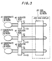
- FIG.3 shows a network composition of a first preferred embodiment of the invention.
- the subordinate optical networks 10 to 12 are connected to the main optical network 20 through repeater nodes 40 to 42.
- the main optical network 20 is composed of a star coupler 210 which has three input ports and three output ports. Signal lights to which optical wavelengths ⁇ 1 to ⁇ 3 are assigned are transmitted from the repeater nodes 40 to 42 to the main optical network 20, then they are coupled and divided in the star coupler 210 and are transmitted to the respective repeater nodes.
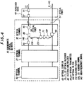
- FIG.4 shows a detailed composition of the subordinate optical network 10 and repeater node 40.
- the subordinate optical network 10 comprises optical terminals 30 to 32 which are cascaded along optical fiber transmission lines 50 and 51 which originates and terminates at the repeater node 40.
- the carrier, frequencies f1 to f3 are assigned to the optical terminals 30 to 32.
- subcarrier multiplexing repeaters are employed as a multiplexing manner of a signal transmitted from an optical terminal.
- an optical receiver 70 receives a signal light transmitted from the optical, terminal 31 and then outputs a high-frequency signal 140.
- An optical transmitter 90 transmits a signal light which is modulated with a high-frequency signal in which the high-frequency signal 140 and a carrier signal 130 with frequency f3 is multiplexed by an electric multiplexer 80. In this manner, only one signal light is transmitted between the optical terminals. Therefore, since the wavelength of a signal light is not limited, a low-cost light source can be used.
- the subcarrier multiplexing repeaters is in detail reported in, for example, W.
- the signal light transmitted from the optical terminal 32 is converted into a signal light with wavelength ⁇ 1 by the repeater node 40 which comprises an optical receiver 72 and optical transmitter 91.
- the signal light with wavelengths ⁇ 1 to ⁇ 3 which is transmitted from the main optical network 10 to the repeater node 40 is transmitted on an optical fiber transmission line 51 as it is.
- a part of the signal light is divided at an optical coupler 60, being filtered by an optical filter to select a signal light with a desired wavelength, then being received by an optical receiver 71. Further, from the output signal of the optical receiver 71, a desired carrier signal 131 is selected by an electric filter.
- three optical wavelengths of ⁇ 1, ⁇ 2 and ⁇ 3 which are 1.53, 1.55 and 1.57 ⁇ m, respectively and three carrier frequencies of f1, f2 and f3 which are 500, 600 and 700 MHz, respectively are employed.
- the length of a transmission line between the respective optical terminals is 20 km, and thus the large-scale subordinate optical networks with a total transmission distance of 60 km is realized.
- the number of optical fiber transmission lines for the subordinate optical networks is two. The transmission lines can be sufficiently used.
- the signal light with wavelength ⁇ 1 is transmitted from the repeater node 40.
- the signal light with wavelength ⁇ 1 may be directly transmitted from the optical terminal 32 to the main optical network 10.
- the optical terminal 32 can function as a repeater node, then the repeater node 40 is not needed.
- the repeater node 40 or optical fiber transmission line 51 may include an optical amplifier for compensating a transmission loss or a division loss at the optical coupler.
- the optical amplifier is needed to simultaneously amplify a plurality of signal lights with different wavelengths.
- an optical amplifier for the simultaneous amplifying of a multi-wavelength signal light is shown in M. Misono et al., "Er-Doped Fiber Amplifier for WDM Networks Using Automatic Gain Control", The Institute of Electronics Information and Communication Engineers, Autumn Meeting, B-943(1994).
- FIG.5 shows a subordinate optical network 10 and repeater node 40 of an optical network in a second preferred embodiment, and the whole composition thereof is similar to that in the first embodiment as shown in FIG.3.
- a, repeater node 40 employs a carrier signal relocation circuit, and a bi-directional optical transmission between the repeater node and optical terminals are performed on a optical fiber transmission line.
- the optical terminals 30 to 32 are cascaded on a loop-shaped optical fiber transmission line 50 which originates and terminates at the repeater node 40.
- This embodiment also employs subcarrier multiplexing repeaters.
- a signal light 120 with wavelengths ⁇ 1 to ⁇ 3 which is transmitted from the main optical network 10 is input to a carrier signal relocation circuit 170 in the repeater node 40.
- the carrier signal relocation circuit 170 comprises an optical coupler 60, optical filters 100 to 102, optical receivers 72 to 74, electric filters 111 to 113 and frequency converters 160 to 162.
- the carrier signal relocation circuit 170 extracts carrier signals which will be received by the optical terminal by the optical filters 100 to 102 with a variable wavelength pass band and the electric filters 111 to 113 with a variable frequency pass band, further converting the frequency of the extracted carrier signals by the frequency converters 160 to 162 to relocate them as desired frequency bands.
- the carrier signals output from the carrier signal relocation circuit 170 are multiplexed in an electric multiplexer 80 and then are input to an optical transmitter 92. From the optical transmitter 92, a signal light 121 modulated by these carrier signals is transmitted to an optical fiber transmission line 50.
- an optical terminal 30 a part of a high-frequency signal output from an optical receiver 70 which receives the signal light 121 is demultiplexed at an electric multi/demultiplexer 150, than the demultiplexed signal is passed through an electric filter 110 to obtain a desired carrier signal 130.
- the high-frequency signal output from the optical receiver 70 is multiplexed with a carrier signal 131 by the electric multi/demultiplexer 150 and is then transmitted from an optical transmitter 90 to the other optical terminal.
- the other optical terminal can get a desired carrier signal.
- the frequencies of f1, f2 and f3 of carrier signals which are transmitted from the optical terminals 30 to 32 are 500, 550 and 600 MHz, respectively and the frequencies of f4, f5 and f6 of carrier signals which are received by the optical terminals 30 to 32 are 700, 750 and 800 MHz, respectively.
- the carrier signals to be received by the optical terminals 30 to 32 are relocated to the frequencies f4 to f6 in the repeater node 40 and are then transmitted to the subordinate optical network 10 to be received by the respective optical terminals.
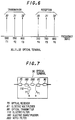
- the frequencies of carrier signals which are transmitted and received at the respective optical terminals may be common by a drop-insert type optical terminal as shown in FIG.7.
- a carrier frequency f1 is assigned to the optical terminal 30.
- the reception of a carrier signal is carried out such that a carrier signal with a frequency f1 is extracted from a high-frequency signal output from the optical receiver 70 by the electric filter 110.
- the transmission of a carrier signal is carried out such that the high-frequency signal output from the optical receiver 70 is passed through a notch filter 220 which removes only the carrier signal with a frequency f1 then multiplexing a carrier signal in the vacant frequency band.
- the electric frequency band can be reduced to one half due to the common frequency of the carrier signal by the optical terminal which has the drop-insert function.
- the carrier signal relocation circuit 170 may include a fixed wavelength optical filter and an electric switch as shown in FIG.8.
- the carrier signal relocation circuit 170 comprises an optical coupler 60, optical filters 100 to 102, optical receivers 72 to 74, electric demultiplexers 180 to 182, electric switches 230 to 232, electric filters 111 to 113 and frequency converters 160 to 162.
- the wavelength pass band of the optical filters 100 to 102 is fixed, and all signal lights are converted into high-frequency signals by the optical receivers 72 to 74.
- the high-frequency signals are demultiplexed by the electric demultiplexers 180 to 182 and are then input to the electric switches 230 to 232.
- the respective electric switches 230 to 232 output any one of the high-frequency signals input.
- the electric switch functions as a selector of the signal light.
- the frequencies of the carrier signals which are extracted from the high-frequency signals output from the electric switches by the electric filters 111 to 113 are converted by the frequency converters 160 to 162 to relocate in a desired frequency band.
- the optical coupler 60 and optical filters 100 to 102 may be replaced by an optical demultiplexer in which a signal light with a different wavelength is output from a different port.
- Such optical demultiplexer is, for example, shown in S.
- FIG.9 shows a subordinate optical network 10 and repeater node 40 of an optical network in a third preferred embodiment, and the whole Composition thereof is similar to that in the first embodiment as shown in FIG.3.
- signal lights transmitted from the respective optical terminals are multiplexed on the optical fiber transmission line.
- optical terminals 30 to 32 are connected by the optical transmission lines 50, 51.
- an optical coupler 60 connected with an optical transmitter 90 which transmits a signal light is inserted on the optical fiber transmission line 50.
- the signal light transmitted from the optical transmitter 90 is multiplexed with a signal light transmitted from the optical terminal 31 by the optical coupler 60.
- beat noise due to the interference of the signal lights may be generated in an optical receiver 70 since all the signal lights transmitted from the optical terminals 30 to 32 are simultaneously received by the optical receiver 70.
- the beat noise is generated in the carrier signal frequency band, noise characteristics are significantly degenerated.
- the wavelengths of the respective signal lights are controlled not to be overlapped each other.
- Such beat noise is, for example, explained in M. Shibutani et al.,"Optical Transmission Networks for Wide Area Video Monitoring Systems", Technical Report of The Institute of Electronics Information and Communication Engineers, OCS92-25(1992).
- the signal light transmitted from the respective optical terminals is converted into a signal light with a wavelength ⁇ 1 which is assigned to the subordinate optical network 10 in the repeater node 40 and are then transmitted to the main optical network 20.
- ⁇ 1 which is assigned to the subordinate optical network 10 in the repeater node 40
- the main optical network 20 since the wavelength of the signal light is converted into a wavelength assigned to the respective subordinate optical networks in the repeater node, with an optional wavelength can be used in the subordinate optical network.
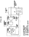
- FIG.10 shows a subordinate optical network 10 and repeater node 40 of an optical network in a fourth preferred embodiment, and the whole composition thereof is similar to that in the first embodiment as shown in FIG.3.
- optical terminals 30 to 32 are connected by a loop-type optical fiber transmission line 50.
- the frequencies of transmission carrier signals of f1, f2 and f3 and frequencies of reception carrier signals of f4, f5 and f6 are assigned to the optical terminals 30 to 32.
- cascaded optical modulators are employed to multiplex a signal light transmitted from an optical terminal.
- a carrier signal with a frequency f1 is applied to an optical modulator 190.
- a signal light 120 is modulated by the carrier signal when it passes through the optical modulator 190.
- the signal light is similarly modulated.
- the signal light 121 output from the optical terminal 32 is modulated by the carrier signals with wavelengths f1 to f3.
- the composition of the cascaded optical modulators is, for example, shown in W. Domon et al., "SCM Optical Multiple-Access Networks with Cascaded Optical Modulators", The Institute of Electronics Information and Communication Engineers, Spring Meeting, SB-9-4(1993).
- the carrier signals received by the respective optical terminals are converted into those with frequencies f4 to f6 in the repeater node 40 similarly to the second embodiment as shown in FIG.2, thereafter being transmitted to the subordinate optical network 10.
- the respective optical terminals include semiconductor optical amplifiers 200 to compensate the insertion loss of the optical modulator, wherein the semiconductor optical amplifier 200 also functions as an optical receiver as well as an amplifier.
- a high-frequency signal output from the semiconductor optical amplifier 200 is passed through an electric filter 110 to obtain a carrier signal with a frequency f4.
- the semiconductor optical amplifier is, for example, shown in K. T.
- the signal light transmitted from the optical transmitter 90 may be directly transmitted to a WDM network when a wavelength thereof is that assigned to the subordinate optical network.
- the optical receiver and optical transmitter which convert the wavelength of a signal light from the subordinate optical network and transmit to the main optical network are not needed in the repeater node.
- FIG.11 shows a subordinate optical network 10 and repeater node 40 of an optical network in a fifth preferred embodiment, and the whole composition thereof is similar to that in the first embodiment as shown in FIG.3.
- optical terminals and repeater node are connected by a single-star type optical fiber transmission line.
- Three signal lights transmitted from the respective optical terminals are modulated by carrier signals with frequencies different with each other.
- Each of the signal lights is transmitted on the optical fiber transmission line different with each other, being converted into with a wavelength ⁇ 1 in the repeater node 40 and transmitted to the main optical network 20.
- optical transmitter 90 to 92 can employ even a cheap light source which does not have a good distortion property and is not easily modulated by a plurality of carrier signals.
Landscapes
- Engineering & Computer Science (AREA)
- Computer Networks & Wireless Communication (AREA)
- Signal Processing (AREA)
- Optical Communication System (AREA)
Applications Claiming Priority (2)
| Application Number | Priority Date | Filing Date | Title |
|---|---|---|---|
| JP311691/94 | 1994-12-15 | ||
| JP6311691A JP2888272B2 (ja) | 1994-12-15 | 1994-12-15 | 光ネットワークおよび中継ノード |
Publications (2)
| Publication Number | Publication Date |
|---|---|
| EP0717521A2 true EP0717521A2 (de) | 1996-06-19 |
| EP0717521A3 EP0717521A3 (de) | 1999-03-17 |
Family
ID=18020310
Family Applications (1)
| Application Number | Title | Priority Date | Filing Date |
|---|---|---|---|
| EP95119837A Withdrawn EP0717521A3 (de) | 1994-12-15 | 1995-12-15 | Optisches Netzwerk mit Unterträger-Multiplexing |
Country Status (3)
| Country | Link |
|---|---|
| US (2) | US5771111A (de) |
| EP (1) | EP0717521A3 (de) |
| JP (1) | JP2888272B2 (de) |
Cited By (12)
| Publication number | Priority date | Publication date | Assignee | Title |
|---|---|---|---|---|
| EP0817410A2 (de) * | 1996-06-27 | 1998-01-07 | Robert Bosch Gmbh | Endgerät für ein optisches Netz, optisches Netz und Endvermittlungsstelle hierfür |
| WO1999056426A1 (en) * | 1998-04-27 | 1999-11-04 | Ciena Corporation | Wdm ring transmission system |
| WO2000042727A1 (en) * | 1999-01-13 | 2000-07-20 | Kestrel Solutions, Inc. | Optical communications networks utilizing frequency division multiplexing |
| GB2352104A (en) * | 1999-07-15 | 2001-01-17 | Marconi Comm Ltd | Upgrading from a single wavelength to a multi-wavelength optical communications system |
| US6407843B1 (en) | 1998-03-05 | 2002-06-18 | Kestrel Solutions, Inc. | System and method for spectrally efficient transmission of digital data over optical fiber |
| US7146103B2 (en) | 1999-12-29 | 2006-12-05 | Forster Energy Llc | Optical communications using multiplexed single sideband transmission and heterodyne detection |
| US7154914B1 (en) | 1998-03-05 | 2006-12-26 | Forster Energy Llc | Through-timing of data transmitted across an optical communications system utilizing frequency division multiplexing |
| US7209660B1 (en) | 1999-12-29 | 2007-04-24 | Forster Energy Llc | Optical communications using heterodyne detection |
| US7228077B2 (en) | 2000-05-12 | 2007-06-05 | Forster Energy Llc | Channel gain control for an optical communications system utilizing frequency division multiplexing |
| US7447436B2 (en) | 1999-12-29 | 2008-11-04 | Forster Energy Llc | Optical communications using multiplexed single sideband transmission and heterodyne detection |
| US7555008B2 (en) | 2001-02-14 | 2009-06-30 | Forster Energy Llc | Method and apparatus for providing a Gigabit Ethernet circuit pack |
| US7620318B2 (en) | 2002-03-25 | 2009-11-17 | Ji Li | Optical transceiver using heterodyne detection and a transmitted reference clock |
Families Citing this family (21)
| Publication number | Priority date | Publication date | Assignee | Title |
|---|---|---|---|---|
| US6075631A (en) * | 1997-09-05 | 2000-06-13 | Bell Communications Research, Inc. | Hitless reconfiguration of a wavelength division multiplexed optical communication network |
| US6647208B1 (en) * | 1999-03-18 | 2003-11-11 | Massachusetts Institute Of Technology | Hybrid electronic/optical switch system |
| JP3772594B2 (ja) | 1999-07-15 | 2006-05-10 | 富士通株式会社 | 光ネットワーク中継装置 |
| US6597479B1 (en) | 1999-10-22 | 2003-07-22 | Adtran, Inc. | Fiber quadrupler device method for providing full duplex communications to a synchronous optical network over a single optical fiber |
| KR100363884B1 (ko) * | 1999-12-27 | 2002-12-11 | 한국전자통신연구원 | 파장분할다중 기반 인터넷 프로토콜 망 구조와, 이러한 망구조에서의 패킷 송수신 시스템 및 방법 |
| EP1309097A4 (de) * | 2000-06-30 | 2006-05-03 | Fujitsu Ltd | Prüfverfahren für übertragungsleitungsverluste, slave-station, das das verfahren einsetzt, master-station und kommunikationssystem |
| BR0100036A (pt) * | 2001-01-09 | 2002-09-24 | Virtualab Participacoees S A | Sistema e processo de transporte de dados |
| JP2002246683A (ja) * | 2001-02-15 | 2002-08-30 | Toshiba Corp | 光送信器及び光伝送システム |
| EP1271825A1 (de) * | 2001-06-25 | 2003-01-02 | Lucent Technologies Inc. | Verfahren und System zur Übertragung von multiplexierten optischen Nachrichten |
| US7110671B1 (en) | 2001-12-03 | 2006-09-19 | Cheetah Omni, Llc | Method and apparatus for scheduling communication using a star switching fabric |
| US7034975B1 (en) | 2001-12-03 | 2006-04-25 | Cheetah Onmi, Llc | High speed MEMS device |
| US7260655B1 (en) | 2001-12-03 | 2007-08-21 | Cheetah Omni, Llc | Optical routing using star switching fabric with reduced effective switching time |
| US7209657B1 (en) | 2001-12-03 | 2007-04-24 | Cheetah Omni, Llc | Optical routing using a star switching fabric |
| FR2837641B1 (fr) * | 2002-03-21 | 2004-09-10 | Cit Alcatel | Reseau de telecommunications optiques de type metropolitain comprenant un coeur de type en anneau |
| JP4407104B2 (ja) * | 2002-08-30 | 2010-02-03 | 富士ゼロックス株式会社 | 信号伝送システム |
| US7171122B1 (en) | 2002-09-19 | 2007-01-30 | Wellhead Patent, Llc | Fiberoptic data telecommunication system architecture |
| US20040151501A1 (en) * | 2003-02-05 | 2004-08-05 | Johannes Gerdes | Method and system for supervising an optical network termination unit |
| FR2872655A1 (fr) * | 2004-07-01 | 2006-01-06 | France Telecom | Reseau privatif multiservices et modules d'interface permettant de vehiculer, sur un tel reseau, des donnees sous differents formats |
| EP2056495A1 (de) * | 2007-10-29 | 2009-05-06 | Alcatel Lucent | Elektrischer Punkt-zu-Mehrpunkt-Repeater für PON |
| US8929732B2 (en) * | 2009-09-24 | 2015-01-06 | Autonetworks Technologies, Ltd. | On-vehicle communication system, optical communication harness and optical distribution apparatus |
| WO2024038569A1 (ja) * | 2022-08-19 | 2024-02-22 | 三菱電機株式会社 | 光交換装置及び光交換方法 |
Family Cites Families (10)
| Publication number | Priority date | Publication date | Assignee | Title |
|---|---|---|---|---|
| DE3572103D1 (en) * | 1985-02-28 | 1989-09-07 | Ibm | Communication system comprising overlayed multiple-access transmission networks |
| US4759011A (en) * | 1986-03-03 | 1988-07-19 | Polaroid Corporation | Intranetwork and internetwork optical communications system and method |
| US5189414A (en) * | 1986-09-30 | 1993-02-23 | Kabushiki Kaisha Toshiba | Network system for simultaneously coupling pairs of nodes |
| US5210632A (en) * | 1989-05-26 | 1993-05-11 | Hitachi, Ltd. | Signal transmission system having a star coupled repeater |
| JP2777194B2 (ja) * | 1989-05-29 | 1998-07-16 | 株式会社東芝 | 光伝送方式 |
| US5073982A (en) * | 1989-09-01 | 1991-12-17 | General Electric Company | Apparatus for connecting multiple passive stars in a fiber optic network |
| JP3308525B2 (ja) * | 1990-11-30 | 2002-07-29 | 株式会社日立製作所 | ネットワーク |
| JPH06350646A (ja) * | 1993-06-08 | 1994-12-22 | Nec Corp | 光波長選択制御方式 |
| FR2718908B1 (fr) * | 1994-04-13 | 1996-06-21 | France Telecom | Réseau de télécommunication organisé en boucles optiques multicolores reconfigurables. |
| JPH07321744A (ja) * | 1994-05-27 | 1995-12-08 | Nec Corp | 光ネットワークおよびアナログ中継ノード |
-
1994
- 1994-12-15 JP JP6311691A patent/JP2888272B2/ja not_active Expired - Fee Related
-
1995
- 1995-12-15 US US08/573,321 patent/US5771111A/en not_active Expired - Fee Related
- 1995-12-15 EP EP95119837A patent/EP0717521A3/de not_active Withdrawn
-
1997
- 1997-03-05 US US08/811,906 patent/US5847852A/en not_active Expired - Fee Related
Non-Patent Citations (8)
| Title |
|---|
| "SUBCARRIER ENCODED WAVELENGTH DIVISION MULTIPLEXED NETWORK WITH FULL CONNECTIVITY" IBM TECHNICAL DISCLOSURE BULLETIN, vol. 34, no. 2, 1 July 1991, pages 266-268, XP000211104 * |
| CHEUNG K W: "SCALABLE ONE-HOP WAVELENGTH-DIVISION MULTIPLEXED CROSSCONNECT" ELECTRONICS LETTERS, vol. 27, no. 4, 14 February 1991, pages 367-369, XP000213343 * |
| CHOY M M ET AL: "A 200 MB/S PACKET-SWITCHED WDM-SCM NETWORK USING FAST RF TUNING" PROCEEDINGS OF THE SPIE, vol. 1787, 8 September 1992, pages 32-42, XP002050749 * |
| LIEW S C ET AL: "A BROAD-BAND OPTICAL NETWORK BASED ON HIERARCHICAL MULTIPLEXING OF WAVELENGHTS AND RF SUBCARRIERS" JOURNAL OF LIGHTWAVE TECHNOLOGY, vol. 7, no. 11, 1 November 1989, pages 1825-1838, XP000104018 * |
| MAEDA M W ET AL: "WAVELENGTH-DIVISION MULTIPLE-ACCESS NETWORK BASED ON CENTRALIZED COMMON-WAVELENGTH CONTROL" IEEE PHOTONICS TECHNOLOGY LETTERS, vol. 5, no. 1, 1 January 1993, pages 83-85, XP000335407 * |
| MATSUMOTO T: "MULTIPLE-ACCESS OPTICAL NETWORK ARCHITECTURE EMPLOYING A WAVELENGHT-AND-NETWORK-DIVISION-TECHNIQUE: MANDALA" PROCEEDINGS OF THE GLOBAL TELECOMMUNICATIONS CONFERENCE (GLOBECOM), HOUSTON, NOV. 29 - DEC. 2, 1993, vol. VOL. 1, no. -, 29 November 1993, pages 463-467, XP000428099 INSTITUTE OF ELECTRICAL AND ELECTRONICS ENGINEERS * |
| OLSHANSKY R: "MULTIGIGABIT PER SECOND SUBCARRIER MULTIPLEXED OPTICAL FIBRE RING NETWORK" ELECTRONICS LETTERS, vol. 27, no. 23, 7 November 1991, pages 2098-2100, XP000268333 * |
| RAJIV RAMASWAMI ET AL: "A PACKET-SWITCHED MULTIHOP LIGHTWAVE NETWORK USING SUBCARRIER AND WAVELENGTH DIVISION MULTIPLEXING" IEEE TRANSACTIONS ON COMMUNICATIONS, vol. 42, no. 2/03/04, 1 February 1994, pages 1198-1211, XP000447379 * |
Cited By (19)
| Publication number | Priority date | Publication date | Assignee | Title |
|---|---|---|---|---|
| EP0817410A2 (de) * | 1996-06-27 | 1998-01-07 | Robert Bosch Gmbh | Endgerät für ein optisches Netz, optisches Netz und Endvermittlungsstelle hierfür |
| EP0817410A3 (de) * | 1996-06-27 | 2000-08-23 | Robert Bosch Gmbh | Endgerät für ein optisches Netz, optisches Netz und Endvermittlungsstelle hierfür |
| US6407843B1 (en) | 1998-03-05 | 2002-06-18 | Kestrel Solutions, Inc. | System and method for spectrally efficient transmission of digital data over optical fiber |
| US7154914B1 (en) | 1998-03-05 | 2006-12-26 | Forster Energy Llc | Through-timing of data transmitted across an optical communications system utilizing frequency division multiplexing |
| US6452945B1 (en) | 1998-03-05 | 2002-09-17 | Kestrel Solutions, Inc. | Electrical add-drop multiplexing for optical communications networks utilizing frequency division multiplexing |
| US6665496B1 (en) | 1998-04-27 | 2003-12-16 | Ciena Corporation | WDM ring transmission system |
| WO1999056426A1 (en) * | 1998-04-27 | 1999-11-04 | Ciena Corporation | Wdm ring transmission system |
| US6928247B2 (en) | 1998-04-27 | 2005-08-09 | Ciena Corporation | WDM ring transmission system |
| US6721505B2 (en) | 1998-04-27 | 2004-04-13 | Ciena Corporation | WDM ring transmission system |
| WO2000042727A1 (en) * | 1999-01-13 | 2000-07-20 | Kestrel Solutions, Inc. | Optical communications networks utilizing frequency division multiplexing |
| US6486988B1 (en) | 1999-07-15 | 2002-11-26 | Marconi Communications Limited | Upgrading optical communications systems without traffic interruption |
| GB2352104A (en) * | 1999-07-15 | 2001-01-17 | Marconi Comm Ltd | Upgrading from a single wavelength to a multi-wavelength optical communications system |
| US7146103B2 (en) | 1999-12-29 | 2006-12-05 | Forster Energy Llc | Optical communications using multiplexed single sideband transmission and heterodyne detection |
| US7209660B1 (en) | 1999-12-29 | 2007-04-24 | Forster Energy Llc | Optical communications using heterodyne detection |
| US7447436B2 (en) | 1999-12-29 | 2008-11-04 | Forster Energy Llc | Optical communications using multiplexed single sideband transmission and heterodyne detection |
| US7228077B2 (en) | 2000-05-12 | 2007-06-05 | Forster Energy Llc | Channel gain control for an optical communications system utilizing frequency division multiplexing |
| US7664403B2 (en) | 2000-05-12 | 2010-02-16 | Newell Laurence J | Synchronizing nodes in an optical communications system utilizing frequency division multiplexing |
| US7555008B2 (en) | 2001-02-14 | 2009-06-30 | Forster Energy Llc | Method and apparatus for providing a Gigabit Ethernet circuit pack |
| US7620318B2 (en) | 2002-03-25 | 2009-11-17 | Ji Li | Optical transceiver using heterodyne detection and a transmitted reference clock |
Also Published As
| Publication number | Publication date |
|---|---|
| JPH08167877A (ja) | 1996-06-25 |
| US5771111A (en) | 1998-06-23 |
| US5847852A (en) | 1998-12-08 |
| JP2888272B2 (ja) | 1999-05-10 |
| EP0717521A3 (de) | 1999-03-17 |
Similar Documents
| Publication | Publication Date | Title |
|---|---|---|
| US5771111A (en) | Optical network | |
| US7433594B2 (en) | Node apparatus, optical wavelength division multiplexing network, and system switching method | |
| US6895185B1 (en) | Multi-purpose optical fiber access network | |
| US5107360A (en) | Optical transmission of RF subcarriers in adjacent signal bands | |
| US4545048A (en) | Service integrated digital transmission system | |
| JP3117018B2 (ja) | ネットワーク装置 | |
| US20070104489A1 (en) | Distributed terminal optical transmission system | |
| US20080131125A1 (en) | Loopback-type wavelength division multiplexing passive optical network system | |
| US20100021164A1 (en) | Wdm pon rf/video broadcast overlay | |
| US6091869A (en) | Low loss, optical add/drop WDM node | |
| US20070189772A1 (en) | Hybrid passive optical network using wireless communication | |
| US6400478B1 (en) | Wavelength-division-multiplexed optical transmission system with expanded bidirectional transmission capacity over a single fiber | |
| KR100960110B1 (ko) | 광대역 무선 서비스를 위한 광 백홀 네트워크 | |
| US20070177873A1 (en) | Hybrid passive optical network | |
| US7769294B2 (en) | Optical transmission network | |
| WO1998049794A2 (en) | Low loss, optical add/drop wdm node | |
| US7609970B2 (en) | Add/drop node for an optical communications network | |
| JP3712375B2 (ja) | 同報通信機能を有する双方向型光波長分割多重伝送システム用光送受信装置 | |
| JP3712372B2 (ja) | 一心双方向型光波長分割多重伝送システム | |
| JP2003234721A (ja) | 光通信システム | |
| EP3937401B1 (de) | Verfahren und vorrichtung zur migration von datenverkehr von einem bestehenden optischen wdm-übertragungssystem zu einem neuen optischen wdm-übertragungssystem | |
| JP3535937B2 (ja) | 光伝送システム | |
| JP3293747B2 (ja) | 光波長多重伝送システム | |
| JPH0346842A (ja) | Fdm光伝送装置 | |
| KR20010050135A (ko) | 정보 신호를 전송하는 방법 |
Legal Events
| Date | Code | Title | Description |
|---|---|---|---|
| PUAI | Public reference made under article 153(3) epc to a published international application that has entered the european phase |
Free format text: ORIGINAL CODE: 0009012 |
|
| AK | Designated contracting states |
Kind code of ref document: A2 Designated state(s): DE FR GB |
|
| PUAL | Search report despatched |
Free format text: ORIGINAL CODE: 0009013 |
|
| AK | Designated contracting states |
Kind code of ref document: A3 Designated state(s): DE FR GB |
|
| 17P | Request for examination filed |
Effective date: 19990317 |
|
| 17Q | First examination report despatched |
Effective date: 20020723 |
|
| STAA | Information on the status of an ep patent application or granted ep patent |
Free format text: STATUS: THE APPLICATION HAS BEEN WITHDRAWN |
|
| 18W | Application withdrawn |
Effective date: 20030117 |