EP0717508B1 - Leistungsregelung in einem beweglichen Satellitenkommunikationssystem - Google Patents
Leistungsregelung in einem beweglichen Satellitenkommunikationssystem Download PDFInfo
- Publication number
- EP0717508B1 EP0717508B1 EP95308993A EP95308993A EP0717508B1 EP 0717508 B1 EP0717508 B1 EP 0717508B1 EP 95308993 A EP95308993 A EP 95308993A EP 95308993 A EP95308993 A EP 95308993A EP 0717508 B1 EP0717508 B1 EP 0717508B1
- Authority
- EP
- European Patent Office
- Prior art keywords
- transmission power
- received signal
- signal level
- mobile station
- base station
- Prior art date
- Legal status (The legal status is an assumption and is not a legal conclusion. Google has not performed a legal analysis and makes no representation as to the accuracy of the status listed.)
- Expired - Lifetime
Links
Images


Classifications
-
- H—ELECTRICITY
- H04—ELECTRIC COMMUNICATION TECHNIQUE
- H04W—WIRELESS COMMUNICATION NETWORKS
- H04W52/00—Power management, e.g. Transmission Power Control [TPC] or power classes
- H04W52/04—Transmission power control [TPC]
- H04W52/18—TPC being performed according to specific parameters
- H04W52/22—TPC being performed according to specific parameters taking into account previous information or commands
- H04W52/228—TPC being performed according to specific parameters taking into account previous information or commands using past power values or information
-
- H—ELECTRICITY
- H04—ELECTRIC COMMUNICATION TECHNIQUE
- H04B—TRANSMISSION
- H04B7/00—Radio transmission systems, i.e. using radiation field
- H04B7/14—Relay systems
- H04B7/15—Active relay systems
- H04B7/185—Space-based or airborne stations; Stations for satellite systems
- H04B7/1853—Satellite systems for providing telephony service to a mobile station, i.e. mobile satellite service
- H04B7/18539—Arrangements for managing radio, resources, i.e. for establishing or releasing a connection
- H04B7/18543—Arrangements for managing radio, resources, i.e. for establishing or releasing a connection for adaptation of transmission parameters, e.g. power control
-
- H—ELECTRICITY
- H04—ELECTRIC COMMUNICATION TECHNIQUE
- H04W—WIRELESS COMMUNICATION NETWORKS
- H04W52/00—Power management, e.g. Transmission Power Control [TPC] or power classes
- H04W52/04—Transmission power control [TPC]
- H04W52/18—TPC being performed according to specific parameters
- H04W52/22—TPC being performed according to specific parameters taking into account previous information or commands
- H04W52/225—Calculation of statistics, e.g. average or variance
Definitions
- the present invention relates to a mobile communication system in which base stations are connected to mobile stations through a communication satellite, and in particular to a mobile satellite communication system and a transmission power control method in the system capable of achieving highly accurate transmission power control of forward links from a base station to mobile stations.
- transmission power control is carried out between a base station and mobile stations.
- the base station determines optimal transmission power using information on received signal levels fed from the mobile stations. This is performed for reducing interference between channels.
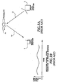
- Figs. 1A and 1B are diagrams illustrating radio-wave propagation characteristics in a cellular system.
- a radio wave radiated from a base station 1 arrives at a mobile station 2 through multipaths in the form of a direct wave 4 and reflected waves 5 reflected on buildings 3 or the like. Accordingly, the radio-wave propagation characteristics are determined by multipath fading, and the received power level of the mobile station 2 sharply varies in short periods as shown in Fig. 1B. This enables the mobile station 2 to obtain a considerably accurate average received signal level by detecting the level of a signal in a short period.
- the mobile station 2 informs the base station 1 of the average received signal level, and the base station 1 controls the forward link transmission power to the mobile station 2 on the basis of the information.
- Fig. 2 is a diagram illustrating the forward link transmission power control.
- the mobile station 2 calculates the average received signal level at each measuring period T, and informs the base station 1 of the values.
- the base station 1 transmits at the transmission power corresponding to the level each time the average received signal level information is provided as shown in Fig. 2(A).
- the control error E contained in the transmission power control value of the base station is kept approximately constant regardless of the transmission power as shown in Fig. 2(C). This is because the measuring period at the mobile station 2 is constant.
- the transmission power control is chiefly needed for effectively availing the power of the satellite.
- Figs. 3A and 3B are diagrams illustrating radio-wave propagation characteristics of a mobile satellite communication system.
- a radio wave radiated from the base station 1 reaches a satellite 10 through a path 11, is repeated by the satellite, and arrives at the mobile station 2 through a path 12.
- the radio-wave propagation characteristics of the mobile satellite communication system do not exhibit multipath fading characteristics as in the cellular system, and the direct wave from the satellite 10 to the mobile station 2 is dominant.
- the variation in the mobile satellite communication system exhibits Rice fading of about 1 Hz in bandwidth and a C/M (Carrier-to-Multipath fading) of an order of ten dB.
- an accurate average received signal level cannot be expected by short period measurement.
- the transmission power control as employed in the cellular system presents a problem in the mobile satellite communication system in that it cannot provide accurate transmission power control. This will result in considerable degradation in channel quality and poor availability of the satellite power.
- US-A-5305468 discloses a power control method for use in a communication system in which a procedure is performed at a base station to control the transmission power of a mobile station.
- changes in the required power are predicted by basing power adjustment commands on the current reception power value, a power slope representing a change of the power value of the signal and the change in power slope representing the rate of change of the power value of the transmitted signal.
- the mobile station may further comprise means for setting an initial value P 0 of the transmission power at a predetermined value.
- the means for calculating a transmission power control amount may obtain the present transmission power control amount ⁇ P k of the base station by adding the level setting error ⁇ S k to a difference between the reference value R ref of the received signal level and the corrected average received signal level R k .
- the means for obtaining the measuring error may obtain the measuring error ⁇ D k by dividing a predetermined value C by a square root of the total measuring time t k .
- the means for obtaining corrected average received signal level may obtain the corrected average received signal level R k by the following equation:
- a base station for use in a mobile satellite communication system in which in use of the system the base station is connected with a mobile station via a communication satellite, said base station comprising: means arranged to extract a corrected average received signal level R k from a received signal sent from said mobile station; means arranged to calculate a transmission power control amount ⁇ P k of said base station on the basis of a prestored level setting error ⁇ S k and a difference between said corrected average received signal level R k and a predetermined reference value R ref of the received signal level of said mobile station; means arranged to obtain the current transmission power P k from said transmission power control amount ⁇ P k and the preceding transmission power P k-1 , and for controlling the transmission power of said base station by said current transmission power P k ; and means arranged to transmit information on said present transmission power control amount ⁇ P k to said mobile station.
- a transmission power control method in a base station connected, in a mobile satellite communication system with a mobile station via a communication satellite comprising: extracting a corrected average received signal level R k from a received signal sent from said mobile station; calculating a transmission power control amount ⁇ P k of said base station on the basis of a prestored level setting error ⁇ S k and a difference between said corrected average received signal level R k and a predetermined reference value R ref of the received signal level of said mobile station; obtaining present transmission power P k from said transmission power control amount ⁇ P k and preceding transmission power P k-1 , and controlling the transmission power of said base station by said present transmission power P k ; and transmitting information on said present transmission power control amount ⁇ P k to said mobile station.
- FIGs. 4 and 5 are block diagrams showing a first embodiment of a mobile satellite communication system in accordance with the present invention, where Fig. 4 shows a base station, and Fig. 5 shows a mobile station.
- a mobile station measures a received signal level at a constant measuring period T.
- VOX Voice Operated Transmission
- a carrier is emitted only when a speech spurt is present.
- the mobile station does not receive the radio wave continuously from the base station.
- T k the time during which the radio wave is actually received in the measuring period, where k is the number indicating measuring sequence and taking values of 1, 2, 3, ...
- An average received signal level during the measuring period T that is, a value obtained by dividing a time integral of the measured received signal level by the actual measuring time T k is referred to as an average received signal level Q k .
- the sum total of the actual measuring times T k is referred to as a total measuring time t k .
- a corrected value of the average received signal level calculated over the total measuring time t k is referred to as a corrected average received signal level R k .
- a signal transmitted from a mobile station is received by an antenna 21, and is fed to a receiving amplifier 25 via a diplexer 23.
- the received signal amplified by the receiving amplifier 25 is detected and demodulated by a receiver 27, and is outputted from an output terminal 29 of the receiver as received data.
- the receiver 27 also extracts an average received signal level Q k and an actual measuring time T k from the received signal.
- Fig. 6 is a schematic diagram showing a format of a signal SG including the information on the average received signal level Q k and the actual measuring time T k .
- the signal SG is inserted into the received signal, and contains a signal identifier ID indicating the type of the signal, and information on the average received signal level Q k and the actual measuring time T k .
- the receiver 27 extracts the signal SG from the received signal, and supplies a calculator 31 with the average received signal level Q k and the actual measuring time T k .
- the calculator 31 calculates, in a manner which will be described later, a total measuring time t k , a corrected average received signal level R k , a received signal level measuring error ⁇ D k , a total error ⁇ E k and a transmission power control amount ⁇ P k . Part of the calculation results is fed to a memory 33 and a controller 35.
- the memory 33 stores the latest data on the total measuring time and the corrected average received signal level.
- the controller 35 calculates transmission power P k on the basis of the transmission power control amount ⁇ P k fed from the calculator 31, details of which will also be described later.
- Transmission data inputted to an input terminal 41 of a transmitter 43 is framed into a predetermined format, and is modulated and fed to a transmitting amplifier 45 as a transmitted signal.
- the transmitting amplifier 45 supplies the antenna 21 via the diplexer 23 with the transmission signal having transmission power determined by a transmission power control signal fed from the controller 35, thereby transmitting it to mobile stations.
- a mobile station as shown in Fig. 5 receives the signal from the base station by an antenna 51.
- the received signal is fed to a receiver 57 through a diplexer 53 and a receiving amplifier 55.
- the receiver 57 demodulates the received signal, and outputs the demodulated data (received data) from an output terminal 59 of the receiver.
- the receiver 57 also supplies a measuring block 61 with the received data and the received signal.
- the measuring block 61 measures the level of the received signal, obtains the average received signal level Q k at each measuring period T determined in advance, and feeds the average received signal level Q k and the actual measuring time T k to a transmitter 73.
- a transmitter 73 inserts the average received signal level Q k and the actual measuring time T k into the transmitted data inputted to an input terminal 71 of the transmitter in the fashion as shown in Fig. 6, and provides it to a transmitting amplifier 75 as a transmitted signal.
- the transmitting amplifier 75 supplies the transmitted signal to the antenna 51 via the diplexer 53, thereby transmitting it to the base station.
- Fig. 7 is a block diagram showing the calculator 31 and the controller 35 of the base station.
- the calculator 31 includes a total measuring time calculator 311, a corrected average received signal level calculator 313, a measuring error calculator 315, a total error calculator 317 and a transmission power control amount calculator 319.
- the total measuring time calculator 311 sequentially sums up the actual measuring time T k which is sent from the mobile station and is fed via the receiver 27 of the base station, thereby obtaining the total measuring time t k equal to the sum total of the actual measuring times T k .
- the total measuring time t k is fed to the corrected average received signal level calculator 313, the measuring error calculator 315 and the memory 33.
- the corrected average received signal level calculator 313 calculates the corrected average received signal level R k given by the following equation.
- R k ⁇ (R k-1 + ⁇ P k-1 )t k-1 + Q k T k ⁇ /t k
- the corrected average received signal level calculator 313 obtains the present corrected average received signal level R k by taking a time average between the present average received signal level Q k and the sum of the corrected average received signal level R k-1 until the end of the preceding measurement and the preceding transmission power control amount ⁇ P k-1 .
- the total measuring time t k-1 , the corrected average received signal level R k-1 and the transmission power control amount ⁇ P k-1 at the end of the preceding measurement are fed from the memory 33.
- the total measuring time t k until the end of the present measurement is fed from the total measuring time calculator 311, and the present actual measuring time T k and average received signal level Q k are fed from the receiver 27.
- the level setting error ⁇ S k is fed from the memory 33.
- the total error ⁇ E k is supplied to the transmission power control amount calculator 319.
- the controller 35 includes a transmission power calculator 351.
- the transmission power P k is fed to the transmitting amplifier 45 so that the transmission power thereof equals the transmission power P k .
- the thus obtained corrected average received signal level R k , transmission power control amount ⁇ P k and total measuring time t k are stored in the memory 33. These data are necessary for calculating the next corrected average received signal level.
- Fig. 8 is a block diagram showing the internal configuration of the measuring block 61 of the mobile station.
- the measuring block 61 includes a measuring period controller 611 and a received signal level detector 613.
- the measuring period controller 611 extracts the frame period from the received signal, and multiplies it by a predetermined integer to obtain the measuring period.
- the measuring period controller 611 also measures the actual measuring time T k by searching the VOX control signal. Since the VOX is controlled on the frame basis, the actual measuring time T k can be measured by counting the number of frames including speech spurts, and by multiplying that number by the length of the received frame.
- the measuring period controller 611 provides the measuring period T and the actual measuring time T k to the received signal level detector 613.
- the received signal level detector 613 measures the received signal level L(t) in each measuring period fed from the measuring period controller 611, and obtains the average received signal level Q k .
- the average received signal level Q k can be obtained either by dividing the time integral of the received signal level L(t) by the actual measuring time T k , or by measuring the bit error rate at every measuring period, and converting it into the received signal level by using a conversion table prestored in the mobile station, either of which can be readily implemented.
- the measuring period is denoted by T (a fixed value).
- the actual measuring time T k and the total measuring time t k as shown in Fig. 9 depend on the time in which the radio wave is actually received as described before. Accordingly, they will become shorter than are indicated in Fig. 9.
- the mobile station measures the received signal level at every measuring period k independently, and calculates the average value thereof.
- the mobile station informs the base station of the average received signal level Q k thus obtained together with the actual measuring time T k each time they are obtained. In other words, the base station receives the average received signal level Q k and the actual measuring time T k at every measuring period.
- the base station sums up the received actual measuring time T k to obtain the total measuring time t k , calculates the corrected average received signal level R k in the total measuring time t k and the measuring error ⁇ D k , and determines the transmission power P k on the basis of these values.
- the measuring error of the average received signal level is inversely proportional to the square root of the measuring time in the mobile satellite communication system as mentioned before. Accordingly, the measuring error will decrease as the measuring time grows longer.
- the total error ⁇ E k contained in the transmission power control amount of the base station gradually decreases as shown in Fig. 9(C).
- the received signal level of the mobile station converges to a desired value in a shorter time than in the conventional mobile station as shown in Fig. 2.
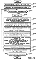
- Figs. 10 and 11 are flowcharts showing details of the above-mentioned operation of the transmission power control, where Fig. 10 shows the operation of the mobile station, and Fig. 11 shows that of the base station.
- Fig. 10 shows the operation of the mobile station
- Fig. 11 shows that of the base station.
- the average received signal levels Q 1 , Q 2 , ... and the actual measuring times T 1 , T 2 , ..., when the base station transmits at the transmission power P 0 , P 1 , ... are sent from the mobile station to the base station. They are sent in the format as shown in Fig. 6 as described before.
- the base station After completing the initial set at step SP11 of Fig. 11, the base station starts transmission at predetermined initial transmission power P 0 at step SP12. The base station keeps this transmission power until it receives the first information on the average received signal level Q 1 from the mobile station.
- the initial transmission power the maximum transmission power of the base station or transmission power determined in advance in accordance with the type of the mobile station is available.
- the receiver 27 of the base station decides whether the next information is received or not from the mobile station at step SP13. Upon receiving the next information, the receiver 27 increments the measuring period number k by one at step SP14, and extracts at step SP15 the k-th average received signal level Q k and actual measuring time T k sent from the mobile station, and supplies them to the calculator 31.
- the total measuring time calculator 311 of the calculator 31 computes the total measuring time t k at step SP16. It is obtained by adding the present actual measuring time T k to the preceding total measuring time t k-1 .
- the measuring error calculator 315 of the calculator 31 computes the measuring error ⁇ D k of the mobile station at step SP17, and the corrected average received signal level calculator 313 calculates the corrected average received signal level R k at step SP18.
- the transmission power control amount calculator 319 of the calculator 31 computes the present transmission power control amount ⁇ P k at step SP19.
- the corrected average received signal level R k , transmission power control amount ⁇ P k and total measuring time t k are stored in the memory 33 at step SP20. These values are necessary for calculating the next corrected average received signal level.
- the transmission power calculator 351 computes the present transmission power P k , and controls the transmitting amplifier 45 such that its transmission power is adjusted to this value.
- the receiver 27 detects whether or not the communications continue, and terminates the processing if it detects the end of the communications. On the other hand, if the communications continue, the receiver returns its control to step SP13, and awaits the next information from the mobile station. Upon receiving the next information, the receiver 27 increments k at step SP14, and repeats similar procedures.
- the present embodiment employs the corrected average received signal level R k over the total measuring time t k instead of the average received signal level Q k in the actual measuring time T k in calculating the transmission power, the measuring time for calculating the average received signal level grows longer. As a result, the present invention can obtain more accurate transmission power than the conventional system.
- the present embodiment obtains the corrected average received signal level R k by equation (2)
- a calculation method is not limited to this. For example, noticing the first term of the right-hand side of equation (2) and equation (4), it is seen that the following equation holds.
- R k-1 + ⁇ P k-1 R ref + ⁇ E k-1
- Substituting the right-hand side of this equation into equation (2) will result in the corrected average received signal level R k . That is, the corrected average received signal level R k can be obtained by the following-equation.
- Figs. 12 and 13 are block diagrams showing a second embodiment of a mobile satellite communication system in accordance with the present invention, wherein Fig. 12 shows a base station and Fig. 13 shows a mobile station.
- the corrected average received signal level R k and the measuring error ⁇ D k are obtained at the mobile station side, and then transmitted to the base station.
- This embodiment basically differs from the first embodiment in the following.
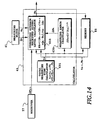
- Fig. 14 is a block diagram showing the internal configuration of the calculator 63 of the mobile station.
- the calculator 63 includes a total measuring time calculator 631, a corrected average received signal level calculator 633, and a measuring error calculator 635.
- the total measuring time calculator 631 calculates the total measuring time t k , the total sum of the actual measuring time T k .
- the total measuring time t k is fed to the corrected average received signal level calculator 633, the measuring error calculator 635 and the memory 65.
- the measuring error calculator 635 calculates the measuring error ⁇ D k of the mobile station over the total measuring time t k .
- the functions of the calculators 631 and 635 are similar to those of their counterparts 311 and 315 in the base station of the first embodiment.
- the corrected average received signal level calculator 633 calculates the corrected average received signal level R k given by the following equation.
- R k ⁇ (R k-1 + ⁇ P k-1 )t k-1 + Q k T k ⁇ /t k - ⁇ D k
- the corrected average received signal level calculator 633 obtains the present corrected average received signal level R k by calculating the time average of the present average received signal level Q k and the sum of the corrected average received signal level R k-1 and the transmission power control amount ⁇ P k-1 at the end point of the preceding measurement, and by subtracting the measuring error ⁇ D k from its result.
- the total measuring time t k-1 and the corrected average received signal level R k-1 at the end of the preceding measurement are fed from the memory 65.
- the transmission power control amount ⁇ P k-1 which is sent from the base station, is fed from the receiver 57.
- the measuring error ⁇ D k is fed from the measuring error calculator 635, the total measuring time t k until the end of the present measurement is fed from the total measuring time calculator 631, and the present actual measuring time T k and the present average received signal level Q k are fed from the measuring block 61.
- the corrected average received signal level R k and the total measuring time t k thus obtained are stored in the memory 65. These are necessary for calculating the next corrected average received signal level.
- the calculator 31 of the base station computes the present transmission power control amount ⁇ P k given by the following equation.
- ⁇ P k R ref - R k + ⁇ S k
- ⁇ S k is a level setting error due to the step values of an attenuator for controlling the transmission power of the base station.
- the present transmission power control amount ⁇ P k is calculated by adding the received signal level reference value and the level setting error, and by subtracting from the sum the present corrected average received signal level R k .
- the controller 35 of the base station calculates the present transmission power P k by the following equation.
- P k P k-1 + ⁇ P k
- the present transmission power P k is obtained by adding the present transmission power control amount ⁇ P k to the preceding transmission power P k-1 .
- the transmitting amplifier 45 is controlled such that its transmission power becomes P k .
- the transmitter 43 of the base station transmits the transmission power control amount ⁇ P k fed from the controller 35 to the mobile station. This value is needed when the mobile station calculates the corrected average received signal level R k .
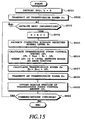
- Figs. 15 and 16 are flowcharts showing in more detail the operation of the transmission power control in the second embodiment, wherein Fig. 15 illustrates the operation of the base station, and Fig. 16 illustrates the operation of the mobile station.
- the base station After completing the initial set at step SP31 of Fig. 15, the base station starts transmission at predetermined initial transmission power P 0 at step SP32.
- the base station keeps the transmission power until the corrected average received signal level R 1 is received from the mobile station.
- the initial transmission power P 0 the maximum transmission power of the base station, or the transmission power predetermined in accordance with the type of the mobile station can be employed.
- the receiver 27 of the base station decides whether the next information is received or not from the mobile station at step SP33. Upon receiving the next information, the receiver 27 increments the measuring period number k by one at step SP34, and extracts at step SP35 the k-th corrected average received signal level R k sent from the mobile station. Subsequently, at step SP36, the calculator 31 computes the present transmission power control amount ⁇ P k by equation (9). At step SP37, the controller 35 of the base station computes the present transmission power P k by equation (10), and controls the transmitting amplifier 45 such that its transmission power is adjusted to P k at step SP38.
- the transmitter 43 of the base station transmits the transmission power control amount ⁇ P k fed from the controller 35 to the mobile station. That amount is needed by the mobile station to calculate the next corrected average received signal level.
- the receiver 27 detects whether or not the communications continue, and the calculator 31 terminates the processing if it detects the end of the communications. On the other hand, if the communications continue, the calculator 31 returns its control to step SP33, and awaits the next information from the mobile station. Upon receiving the next information, the receiver 27 increments k at step SP34, and repeats similar procedures.
- the measuring block 61 of the mobile station starts measuring of the average received signal level simultaneously with the start of the communications. After carrying out the initial set at step SP51 of Fig. 16, the measuring block 61 measures the actual measuring time T k and average received signal level Q k in each predetermined measuring period T at step SP52. The measured average received signal level Q k are fed to the calculator 63 together with the actual measuring time T k .
- the total measuring time calculator 631 of the calculator 63 computes the total measuring time t k at step SP53 by adding the present actual measuring time T k to the preceding total measuring time t k-1 .
- the measuring error calculator 635 of the calculator 63 calculates the measuring error ⁇ D k of the mobile station by equation (1).
- the receiver 57 extracts the preceding transmission power control amount ⁇ P k-1 from the received signal.
- the corrected average received signal level calculator 633 of the calculator 63 computes the corrected average received signal level R k at step SP56.
- the total measuring time t k , the corrected average received signal level R k and the measuring error ⁇ D k are stored in the memory 65. These values are necessary for computing the next corrected average received signal level.
- the calculator 58 informs the base station of the corrected average received signal level R k through the transmitter 73.
- step SP59 The foregoing processing are continued until the end of the communications is detected at step SP59. Specifically, the procedures at step SP52 and the following steps are continued during the communications by incrementing the measuring period number k at step SP61 every time the passing of the measuring period T is detected at step SP60.
- the present embodiment has an advantage that the calculation load of the base station is reduced because the calculation of the corrected average received signal levels is shared by respective mobile stations.
- the present embodiment obtains the corrected average received signal level R k by equation (8)
- a calculation method is not limited to this. For example, noticing the first term of the right-hand side of equation (8) and equation (9), it is seen that the following equation holds.
- R k-1 + ⁇ P k-1 R ref + ⁇ S k-1
- Substituting the right-hand side of this equation into equation (8) will result in the corrected average received signal level R k . That is, the corrected average received signal level R k can be obtained by the following equation.
Landscapes
- Engineering & Computer Science (AREA)
- Computer Networks & Wireless Communication (AREA)
- Signal Processing (AREA)
- Physics & Mathematics (AREA)
- Probability & Statistics with Applications (AREA)
- Astronomy & Astrophysics (AREA)
- Aviation & Aerospace Engineering (AREA)
- General Physics & Mathematics (AREA)
- Mobile Radio Communication Systems (AREA)
- Radio Relay Systems (AREA)
Claims (13)
- Mobiles Satelliten-Kommunikationssystem mit einer Basisstation (1), die mit einer Mobilstation (2) über einen Kommunikationssatelliten (10) verbunden ist,
wobei die Mobilstation umfasst:wobei die Basisstation (1) umfasst:eine Messeinrichtung (61), die dazu angeordnet ist, aufeinander folgende tatsächliche Messzeiten Tk und mittlere empfangene Signalpegel Qk für Werte von k = 1, 2, ... in jeder vorbestimmten Messperiode der Mobilstation T zu ermitteln;eine Einrichtung (631), die dazu angeordnet ist, eine gesamte Messzeit tk zu berechnen, welche eine Gesamtsumme der tatsächlichen Messzeiten Tk am Ende einer gegenwärtigen Messperiode der Mobilstation ist;eine Einrichtung (635), die dazu angeordnet ist, einen Messfehler ΔDk eines mittleren empfangenen Signalpegels in der gesamten Messzeit tk am Ende der gegenwärtigen Messperiode zu ermitteln;eine Speichereinrichtung (65), die dazu angeordnet ist, eine gesamte Messzeit tk-1 und einen korrigierten mittleren empfangenen Signalpegel Rk-1 am Ende einer vorangehenden Messperiode der Mobilstation (2) zu speichern;eine Einrichtung (57), die dazu angeordnet ist, eine Sendeleistung-Steuergröße ΔPk-1 aus einem von der Basisstation zu der Mobilstation gesendeten Signal zu extrahieren;eine Einrichtung (633), die dazu angeordnet ist, einen korrigierten mittleren empfangenen Signalpegel Rk am Ende einer gegenwärtigen Messperiode der Mobilstation (2) auf der Grundlage des korrigierten mittleren empfangenen Signalpegels Rk-1, der Sendeleistung-Steuergröße ΔPk-1, der gesamten Messzeit tk-1, alle am Ende der vorangegangenen Messperiode, und des mittleren empfangenen Signalpegels Qk, der tatsächlichen Messzeit Tk und der gesamten Messzeit tk, alle am Ende der gegenwärtigen Messperiode, zu ermitteln; undeine Sendeeinrichtung (73), die dazu angeordnet ist, die Basisstation über den korrigierten mittleren empfangenen Signalpegel Rk zu informieren; undeine Einrichtung (27), die dazu angeordnet ist, den korrigierten mittleren Signalpegel Rk aus einem von der Mobilstation (2) gesendeten empfangenen Signal zu extrahieren;eine Einrichtung (31), die dazu angeordnet ist, die Sendeleistung-Steuergröße ΔPk der Basisstation auf der Grundlage eines vorgespeicherten Pegeleinstellfehlers ΔSk und einer Differenz zwischen dem korrigierten mittleren empfangenen Signalpegel Rk und einem vorbestimmten Referenzwert Rref des empfangenen Signalpegels der Mobilstation zu berechnen;eine Einrichtung (35), die dazu angeordnet ist, die gegenwärtige Sendeleistung Pk aus der Sendeleistung-Steuergröße ΔPk und der vorangehenden Sendeleistung Pk-1 zu ermitteln, und die Sendeleistung der Basisstation (1) mittels der gegenwärtigen Sendeleistung Pk zu steuern; undeine Einrichtung (43), die dazu angeordnet ist, Informationen über die gegenwärtige Sendeleistung-Steuergröße ΔPk an die Mobilstation (2) zu senden. - Mobiles Satelliten-Kommunikationssystem nach Anspruch 1, bei dem die Mobilstation ferner eine Einrichtung umfasst, die dazu angeordnet ist, einen Anfangswert Po der Sendeleistung auf einen vorbestimmten Wert einzustellen.
- Mobiles Satelliten-Kommunikationssystem nach Anspruch 1 oder Anspruch 2, bei dem die Einrichtung (31), die dazu angeordnet ist, eine Sendeleistung-Steuergröße zu berechnen, so betreibbar ist, dass die gegenwärtige Sendeleistung-Steuergröße ΔPk der Basisstation (1) durch Hinzuaddieren des Pegeleinstellfehlers ΔSk zu der Differenz zwischen dem Referenzwert Rref des empfangenen Signalpegels und dem korrigierten mittleren empfangenen Signalpegel Rk berechnet wird.
- Mobiles Satelliten-Kommunikationssystem nach einem der Ansprüche 1 bis 3, bei dem die Einrichtung (635) die dazu angeordnet ist, den Messfehler zu ermitteln, so betreibbar ist, dass der Messfehler ΔDk durch Dividieren eines vorbestimmten Werts C durch die Quadratwurzel der gesamten Messzeit tk am Ende der gegenwärtigen Messperiode T ermittelt wird.
- Mobiles Satellitenkommunikationssystem nach einem der Ansprüche 1 bis 4, bei dem die Einrichtung (633), die dazu angeordnet ist, den korrigierten mittleren empfangenen Signalpegel zu ermitteln, so betreibbar ist, dass der korrigierte mittlere empfangene Signalpegel Rk durch die folgende Gleichung ermittelt wird:

- Basisstation zur Verwendung in einem mobilen Satelliten-Kommunikationssystem, bei welchem im Gebrauch des Systems die Basisstation mit einer Mobilstation über einen Kommunikationssatelliten verbunden ist, wobei die Basisstation (1) umfasst:eine Einrichtung (27), die dazu angeordnet ist (27), einen korrigierten mittleren Signalpegel Rk aus einem von der Mobilstation (2) gesendeten empfangenen Signal zu extrahieren;eine Einrichtung (31), die dazu angeordnet ist, eine Sendeleistung-Steuergröße ΔPk der Basisstation (1) auf der Grundlage eines vorgespeicherten Pegeleinstellfehlers ΔSk und einer Differenz zwischen dem korrigierten mittleren empfangenen Signalpegel Rk und einem vorbestimmten Referenzwert Rref des empfangenen Signalpegels der Mobilstation (2) zu berechnen;eine Einrichtung (35), die dazu angeordnet ist, die gegenwärtige Sendeleistung Pk aus der Sendeleistung-Steuergröße ΔPk und der vorangehenden Sendeleistung Pk-1 zu ermitteln, und die Sendeleistung der Basisstation mittels der gegenwärtigen Sendeleistung Pk zu steuern; undeine Einrichtung (43), die dazu angeordnet ist, Informationen über die gegenwärtige Sendeleistung-Steuergröße ΔPk an die Mobilstation (2) zu senden.
- Basisstation nach Anspruch 6, bei der die Einrichtung (31), die dazu angeordnet ist, eine Sendeleistung-Steuergröße zu berechnen, so betreibbar ist, dass die gegenwärtige Sendeleistung-Steuergröße ΔPk der Basisstation (1) durch Hinzuaddieren des Pegeleinstellfehlers ΔSk zu einer Differenz zwischen dem Referenzwert Rref des empfangenen Signalpegels und dem korrigierten mittleren empfangenen Signalpegel Rk berechnet wird.
- Mobiles Satelliten-Kommunikationsverfahren in einem mobilen Satelliten-Kommunikationssystem, bei welchem eine Basisstation (1) mit einer Mobilstation (2) über einen Kommunikationssatelliten (10) verbunden ist,
wobei das Verfahren umfasst:Ermitteln (SP52), an der Mobilstation (2), einer tatsächlichen Messzeit Tk und eines mittleren empfangenen Signalpegels Qk (k = 1, 2, ...) in jeder vorbestimmten Messperiode T;Berechnen (SP53), an der Mobilstation (2), einer gesamten Messzeit tk, welche eine Gesamtsumme der tatsächlichen Messzeiten Tk am Ende einer gegenwärtigen Messperiode der Mobilstation ist;Ermitteln (SP54), an der Mobilstation (2), eines Messfehlers ΔDk eines mittleren empfangenen Signalpegels in der gesamten Messzeit tk;Speichern (SP57), an der Mobilstation (2), einer gesamten Messzeit tk-1 und eines korrigierten mittleren empfangenen Signalpegels Rk-1 am Ende einer vorangehenden Messperiode der Mobilstation (2);Extrahieren (SP55), an der Mobilstation (2), einer Sendeleistung-Steuergröße ΔPk-1 aus einem von der Basisstation (1) zu der Mobilstation (2) gesendeten Signal;Ermitteln (SP56), an der Mobilstation (2), eines korrigierten mittleren empfangenen Signalpegels Rk am Ende einer gegenwärtigen Messperiode der Mobilstation (2) auf der Grundlage des korrigierten mittleren empfangenen Signalpegels Rk-1, der Sendeleistung-Steuergröße ΔPk-1, der gesamten Messzeit tk-1, alle am Ende der vorangegangenen Messperiode, und des mittleren empfangenen Signalpegels Qk, der tatsächlichen Messzeit Tk und der gesamten Messzeit tk, alle am Ende der gegenwärtigen Messperiode; undInformieren (SP56) der Basisstation über den korrigierten mittleren empfangenen Signalpegel Rk;Extrahieren (SP35), an der Basisstation (1), des korrigierten mittleren Signalpegels Rk aus einem von der Mobilstation (2) gesendeten empfangenen Signal;Berechnen (SP36), an der Basisstation (1), der Sendeleistung-Steuergröße ΔPk der Basisstation (1) auf der Grundlage eines vorgespeicherten Pegeleinstellfehlers ΔSk und einer Differenz zwischen dem korrigierten mittleren empfangenen Signalpegel Rk und einem vorbestimmten Referenzwert Rref des empfangenen Signalpegels der Mobilstation (2);Ermitteln (SP37), an der Basisstation (1), die gegenwärtige Sendeleistung Pk aus der Sendeleistung-Steuergröße ΔPk und der vorangehenden Sendeleistung Pk-1, und Steuern (SP38), an der Basisstation (1), der Sendeleistung der Basisstation (1) mittels der gegenwärtigen Sendeleistung Pk; undSenden (SP39) von Informationen über die gegenwärtige Sendeleistung-Steuergröße ΔPk an die Mobilstation (2). - Verfahren nach Anspruch 8, ferner umfassend den Schritt des Einstellens eines Anfangswerts Po der Sendeleistung auf einen vorbestimmten Wert.
- Verfahren nach Anspruch 8 oder Anspruch 9, bei dem der Schritt des Berechnens der Sendeleistung-Steuergröße das Hinzuaddieren des Pegeleinstellfehlers ΔSk zu der Differenz zwischen dem Referenzwert Rref des empfangenen Signalpegels und dem korrigierten mittleren empfangenen Signalpegel Rk umfasst.
- Verfahren nach einem der Ansprüche 8 bis 10, bei dem der Schritt zum Ermitteln des Messfehlers das Dividieren eines vorbestimmten Werts C durch eine Quadratwurzel der gesamten Messzeit tk umfasst.
- Verfahren nach einem der Ansprüche 8 bis 11, bei dem der Schritt zum Ermitteln des korrigierten mittleren empfangenen Signalpegels die folgende Gleichung verwendet:

- Sendeleistung-Steuerverfahren in einer Basisstation (1), die in einem mobilen Satelliten-Kommunikationssystem mit einer Mobilstation (2) über einen Kommunikationssatelliten (10) verbunden ist, wobei das Verfahren umfasst:Extrahieren (SP 35) eines korrigierten mittleren Signalpegels Rk aus einem von der Mobilstation (2) gesendeten empfangenen Signal;Berechnen (SP36) einer Sendeleistung-Steuergröße ΔPk der Basisstation (1) auf der Grundlage eines vorgespeicherten Pegeleinstellfehlers ΔSk und einer Differenz zwischen dem korrigierten mittleren empfangenen Signalpegel Rk und einem vorbestimmten Referenzwert Rref des empfangenen Signalpegels der Mobilstation (2);Ermitteln (SP37) der gegenwärtigen Sendeleistung Pk aus der Sendeleistung-Steuergröße ΔPk und der vorangehenden Sendeleistung Pk-1, und Steuern (SP38) der Sendeleistung der Basisstation (1) mittels der gegenwärtigen Sendeleistung Pk; undSenden (SP39) von Informationen über die gegenwärtige Sendeleistung-Steuergröße ΔPk an die Mobilstation (2).
Priority Applications (2)
| Application Number | Priority Date | Filing Date | Title |
|---|---|---|---|
| EP03075044A EP1300966B1 (de) | 1994-12-13 | 1995-12-11 | Mobile Satelliten Kommunikationsanordnung |
| EP00204675A EP1104118B1 (de) | 1994-12-13 | 1995-12-11 | Sendeleistungsregelung in einem mobilen Satelliten Kommunikationssystem |
Applications Claiming Priority (3)
| Application Number | Priority Date | Filing Date | Title |
|---|---|---|---|
| JP30889394 | 1994-12-13 | ||
| JP30889394 | 1994-12-13 | ||
| JP308893/94 | 1994-12-13 |
Related Child Applications (2)
| Application Number | Title | Priority Date | Filing Date |
|---|---|---|---|
| EP00204675A Division EP1104118B1 (de) | 1994-12-13 | 1995-12-11 | Sendeleistungsregelung in einem mobilen Satelliten Kommunikationssystem |
| EP03075044A Division EP1300966B1 (de) | 1994-12-13 | 1995-12-11 | Mobile Satelliten Kommunikationsanordnung |
Publications (3)
| Publication Number | Publication Date |
|---|---|
| EP0717508A2 EP0717508A2 (de) | 1996-06-19 |
| EP0717508A3 EP0717508A3 (de) | 1996-07-24 |
| EP0717508B1 true EP0717508B1 (de) | 2004-08-04 |
Family
ID=17986538
Family Applications (3)
| Application Number | Title | Priority Date | Filing Date |
|---|---|---|---|
| EP00204675A Expired - Lifetime EP1104118B1 (de) | 1994-12-13 | 1995-12-11 | Sendeleistungsregelung in einem mobilen Satelliten Kommunikationssystem |
| EP95308993A Expired - Lifetime EP0717508B1 (de) | 1994-12-13 | 1995-12-11 | Leistungsregelung in einem beweglichen Satellitenkommunikationssystem |
| EP03075044A Expired - Lifetime EP1300966B1 (de) | 1994-12-13 | 1995-12-11 | Mobile Satelliten Kommunikationsanordnung |
Family Applications Before (1)
| Application Number | Title | Priority Date | Filing Date |
|---|---|---|---|
| EP00204675A Expired - Lifetime EP1104118B1 (de) | 1994-12-13 | 1995-12-11 | Sendeleistungsregelung in einem mobilen Satelliten Kommunikationssystem |
Family Applications After (1)
| Application Number | Title | Priority Date | Filing Date |
|---|---|---|---|
| EP03075044A Expired - Lifetime EP1300966B1 (de) | 1994-12-13 | 1995-12-11 | Mobile Satelliten Kommunikationsanordnung |
Country Status (3)
| Country | Link |
|---|---|
| US (1) | US5835846A (de) |
| EP (3) | EP1104118B1 (de) |
| DE (3) | DE69534236T2 (de) |
Families Citing this family (29)
| Publication number | Priority date | Publication date | Assignee | Title |
|---|---|---|---|---|
| US6031826A (en) * | 1996-08-27 | 2000-02-29 | Ericsson Inc. | Fast associated control channel technique for satellite communications |
| JPH10117166A (ja) * | 1996-10-08 | 1998-05-06 | Nec Ic Microcomput Syst Ltd | 移動体通信システム |
| US6829226B1 (en) * | 1997-04-04 | 2004-12-07 | Ericsson Inc. | Power control for a mobile terminal in a satellite communication system |
| JP3000960B2 (ja) * | 1997-05-28 | 2000-01-17 | 日本電気株式会社 | 移動体衛星通信システムの送信電力制御方式 |
| FR2769158B1 (fr) * | 1997-09-26 | 1999-11-26 | Sagem | Procede de gestion de l'alimentation d'un poste de radiotelephonie cellulaire |
| JP3397677B2 (ja) * | 1998-02-10 | 2003-04-21 | 松下電器産業株式会社 | 送信電力制御装置及び無線通信装置 |
| JP2000101511A (ja) * | 1998-09-24 | 2000-04-07 | Fujitsu Ltd | 加入者系無線アクセスシステムにおける送信レベル制御方法および送受信装置 |
| JP3150115B2 (ja) | 1998-11-12 | 2001-03-26 | 埼玉日本電気株式会社 | Cdma開ループ制御における上りチャネル干渉補正方法及びそのシステム |
| JP2000269759A (ja) * | 1999-03-18 | 2000-09-29 | Matsushita Electric Ind Co Ltd | 自動利得制御回路およびその回路を備えた受信装置、受信装置における自動利得制御方法、並びに、記録媒体 |
| WO2000057572A1 (de) * | 1999-03-18 | 2000-09-28 | Siemens Aktiengesellschaft | Verfahren zur regelung der sendeleistung in einem mobilfunksystem und entsprechendes mobilfunksystem |
| DE19923580B4 (de) * | 1999-05-21 | 2006-03-02 | Robert Bosch Gmbh | Verfahren und Vorrichtung zur Leistungsregelung eines Senders |
| GB2353668B (en) * | 1999-08-25 | 2003-09-24 | Siemens Ag | Power control apparatus and method therefor |
| US6760566B1 (en) * | 2000-06-19 | 2004-07-06 | Northrop Grumman Corporation | Method and apparatus for controlling a transmission power threshold of a satellite communication system |
| FR2816774B1 (fr) * | 2000-11-14 | 2004-05-21 | Nortel Matra Cellular | Procede de dispositif d'evaluation du niveau energitique d'un signal radio |
| EP1371152A1 (de) * | 2001-03-21 | 2003-12-17 | Hughes Electronics Corporation | System und verfahren zur sendeleistungsregelung in geschlossener schleife |
| US7941172B2 (en) | 2002-07-23 | 2011-05-10 | Qualcomm Incorporated | History based measured power control response |
| US20060030272A1 (en) * | 2004-01-21 | 2006-02-09 | Hideyuki Nakamizo | Transceiver and receiver |
| US7599659B2 (en) * | 2005-03-10 | 2009-10-06 | The Boeing Company | Innovative combinational closed-loop and open-loop satellite user terminal power control system |
| GB2481545B (en) * | 2007-02-02 | 2012-03-14 | Ubiquisys Ltd | Access point power control |
| GB2447439B (en) | 2007-02-02 | 2012-01-25 | Ubiquisys Ltd | Access point power control |
| US8200263B2 (en) * | 2007-09-21 | 2012-06-12 | Research In Motion Limited | Apparatus and method for providing uplink interference coordination in a radio communication system |
| JP4383480B2 (ja) * | 2007-11-15 | 2009-12-16 | 株式会社エヌ・ティ・ティ・ドコモ | 移動通信端末及び移動通信端末における送信電力制御方法 |
| US8258942B1 (en) | 2008-01-24 | 2012-09-04 | Cellular Tracking Technologies, LLC | Lightweight portable tracking device |
| GB2471681B (en) | 2009-07-07 | 2011-11-02 | Ubiquisys Ltd | Interference mitigation in a femtocell access point |
| GB2472597B (en) | 2009-08-11 | 2012-05-16 | Ubiquisys Ltd | Power setting |
| EP2824476B1 (de) | 2013-07-12 | 2019-05-08 | Alcatel Lucent | Zeitliche Analyse zur Benutzergeschwindigkeitsschätzung in drahtlosen Netzwerken |
| GB2557628B (en) | 2016-12-13 | 2020-01-01 | Inmarsat Global Ltd | Forward link power control |
| CN110011723A (zh) * | 2019-04-15 | 2019-07-12 | 河南大华安防科技股份有限公司 | 一种基于北斗一键报警的短报文图像步进传输方法 |
| TWI743841B (zh) * | 2020-06-17 | 2021-10-21 | 啟碁科技股份有限公司 | 抑制無線功率變化之方法及其裝置 |
Family Cites Families (8)
| Publication number | Priority date | Publication date | Assignee | Title |
|---|---|---|---|---|
| FR2592256B1 (fr) * | 1985-12-20 | 1988-02-12 | Trt Telecom Radio Electr | Dispositif d'asservissement de la puissance d'emission d'un faisceau hertzien |
| US4868885A (en) * | 1986-05-05 | 1989-09-19 | General Electric Company | Apparatus and method for high-speed determination of received RF signal strength indicator |
| JPS6346824A (ja) * | 1986-08-14 | 1988-02-27 | Kokusai Denshin Denwa Co Ltd <Kdd> | 送信電力制御方式 |
| JPH01147924A (ja) * | 1987-12-03 | 1989-06-09 | Fujitsu Ltd | 2モード送信電力制御方式 |
| JPH01213016A (ja) * | 1988-02-22 | 1989-08-25 | Nec Corp | 自動電力制御回路 |
| DE69231437T2 (de) * | 1991-12-26 | 2001-03-01 | Nec Corp., Tokio/Tokyo | System zur Steuerung der Sendeleistung mit Gewährleistung einer konstanten Signalqualität in einem Mobilkommunikationsnetzwerk |
| US5305468A (en) * | 1992-03-18 | 1994-04-19 | Motorola, Inc. | Power control method for use in a communication system |
| US5423084A (en) * | 1992-05-11 | 1995-06-06 | Motorola, Inc. | Spectrum recovery apparatus and method therefor |
-
1995
- 1995-12-11 DE DE69534236T patent/DE69534236T2/de not_active Expired - Lifetime
- 1995-12-11 EP EP00204675A patent/EP1104118B1/de not_active Expired - Lifetime
- 1995-12-11 DE DE69535386T patent/DE69535386T8/de active Active
- 1995-12-11 DE DE69533327T patent/DE69533327T2/de not_active Expired - Lifetime
- 1995-12-11 EP EP95308993A patent/EP0717508B1/de not_active Expired - Lifetime
- 1995-12-11 EP EP03075044A patent/EP1300966B1/de not_active Expired - Lifetime
- 1995-12-12 US US08/571,126 patent/US5835846A/en not_active Expired - Lifetime
Also Published As
| Publication number | Publication date |
|---|---|
| DE69534236D1 (de) | 2005-06-30 |
| EP0717508A2 (de) | 1996-06-19 |
| EP1104118A3 (de) | 2002-07-24 |
| EP0717508A3 (de) | 1996-07-24 |
| DE69535386T8 (de) | 2007-10-25 |
| EP1104118B1 (de) | 2005-05-25 |
| DE69535386T2 (de) | 2007-06-14 |
| DE69535386D1 (de) | 2007-03-22 |
| EP1300966A3 (de) | 2004-05-19 |
| EP1104118A2 (de) | 2001-05-30 |
| US5835846A (en) | 1998-11-10 |
| DE69533327D1 (de) | 2004-09-09 |
| DE69533327T2 (de) | 2005-07-14 |
| EP1300966B1 (de) | 2007-02-07 |
| EP1300966A2 (de) | 2003-04-09 |
| DE69534236T2 (de) | 2006-01-19 |
Similar Documents
| Publication | Publication Date | Title |
|---|---|---|
| EP0717508B1 (de) | Leistungsregelung in einem beweglichen Satellitenkommunikationssystem | |
| JP3397677B2 (ja) | 送信電力制御装置及び無線通信装置 | |
| EP1041728B1 (de) | Spreizspektrumsystem und -verfahren | |
| US7925211B2 (en) | Method for uplink power control for distributed satellite networks to compensate for rain fade | |
| US6580919B1 (en) | CDMA transmission power control capable of preventing call disconnection and degradation of capacity of subscribers | |
| US7809044B2 (en) | Method and apparatus for forward link power control | |
| EP0851612A1 (de) | Signal-übertragungsverfahren, mobiles endgerät, und basisstationsgerät für mobiles cdma kommunikationssystem | |
| US8160630B2 (en) | Method and arrangement for controlling transmission power and a network element | |
| US20030027529A1 (en) | Method of improving efficiency in a satellite communications system | |
| JPH07500460A (ja) | Cdmaセル運動体電話システムにおける送信パワーを制御する方法および装置 | |
| US11671923B2 (en) | NTN uplink power control | |
| US20040162101A1 (en) | Apparatus and method for measuring thermal noise power in a mobile communication system | |
| EP1024606A2 (de) | Offenen regelkreisleistungsregelung für drahtlose Mobilstationen | |
| US8107959B2 (en) | Mobile communication system and handover control method | |
| US6337975B1 (en) | System and method for power measurement in outdoor antenna units | |
| JPH11177488A (ja) | 移動通信システムの基地局における送信電力制御方法並びに移動通信システムにおける基地局及び移動機 | |
| US20020098814A1 (en) | Method and system for automatic gain control in a satellite communications system | |
| JP2988617B2 (ja) | 移動体衛星通信システム、および同システムにおける送信電力制御方法 | |
| US20020004396A1 (en) | Mobile communication system and method and mobile stations and base stations in the system | |
| JPH10224293A (ja) | 移動局送信電力の制御方法および移動通信方式 | |
| JP2980390B2 (ja) | 衛星間アンテナ指向装置 | |
| KR100718277B1 (ko) | 자동 송신 레벨 조절장치 | |
| JPH0356021B2 (de) | ||
| JPS62188438A (ja) | 送信電力制御方式 |
Legal Events
| Date | Code | Title | Description |
|---|---|---|---|
| PUAI | Public reference made under article 153(3) epc to a published international application that has entered the european phase |
Free format text: ORIGINAL CODE: 0009012 |
|
| PUAL | Search report despatched |
Free format text: ORIGINAL CODE: 0009013 |
|
| AK | Designated contracting states |
Kind code of ref document: A2 Designated state(s): DE GB SE |
|
| AK | Designated contracting states |
Kind code of ref document: A3 Designated state(s): DE GB SE |
|
| 17P | Request for examination filed |
Effective date: 19960821 |
|
| 17Q | First examination report despatched |
Effective date: 20000215 |
|
| RAP1 | Party data changed (applicant data changed or rights of an application transferred) |
Owner name: NTT DOCOMO, INC. |
|
| GRAP | Despatch of communication of intention to grant a patent |
Free format text: ORIGINAL CODE: EPIDOSNIGR1 |
|
| RTI1 | Title (correction) |
Free format text: POWER REGULATION FOR A MOBILE SATELLITE COMMUNICATION SYSTEM |
|
| RTI1 | Title (correction) |
Free format text: POWER REGULATION FOR A MOBILE SATELLITE COMMUNICATION SYSTEM |
|
| RIN1 | Information on inventor provided before grant (corrected) |
Inventor name: KODAMA, EIJI,NTT AOUGADAI DOKUSHINRYO A-306 Inventor name: OHNO, YOSHIHISA Inventor name: KOBAYASHI, HIROSHI Inventor name: NISHI, YASUKI Inventor name: FURUKAWA, KENJI |
|
| GRAS | Grant fee paid |
Free format text: ORIGINAL CODE: EPIDOSNIGR3 |
|
| GRAA | (expected) grant |
Free format text: ORIGINAL CODE: 0009210 |
|
| AK | Designated contracting states |
Kind code of ref document: B1 Designated state(s): DE GB SE |
|
| REG | Reference to a national code |
Ref country code: GB Ref legal event code: FG4D |
|
| REF | Corresponds to: |
Ref document number: 69533327 Country of ref document: DE Date of ref document: 20040909 Kind code of ref document: P |
|
| REG | Reference to a national code |
Ref country code: SE Ref legal event code: TRGR |
|
| PLBE | No opposition filed within time limit |
Free format text: ORIGINAL CODE: 0009261 |
|
| STAA | Information on the status of an ep patent application or granted ep patent |
Free format text: STATUS: NO OPPOSITION FILED WITHIN TIME LIMIT |
|
| 26N | No opposition filed |
Effective date: 20050506 |
|
| PGFP | Annual fee paid to national office [announced via postgrant information from national office to epo] |
Ref country code: DE Payment date: 20141202 Year of fee payment: 20 Ref country code: SE Payment date: 20141211 Year of fee payment: 20 Ref country code: GB Payment date: 20141210 Year of fee payment: 20 |
|
| REG | Reference to a national code |
Ref country code: DE Ref legal event code: R071 Ref document number: 69533327 Country of ref document: DE |
|
| REG | Reference to a national code |
Ref country code: GB Ref legal event code: PE20 Expiry date: 20151210 |
|
| PG25 | Lapsed in a contracting state [announced via postgrant information from national office to epo] |
Ref country code: GB Free format text: LAPSE BECAUSE OF EXPIRATION OF PROTECTION Effective date: 20151210 |
|
| REG | Reference to a national code |
Ref country code: SE Ref legal event code: EUG |