EP0717277B1 - Überprüfen einer Prophylaxevorrichtung auf Löcher mit einem porösen hohlen Einsatzstück - Google Patents
Überprüfen einer Prophylaxevorrichtung auf Löcher mit einem porösen hohlen Einsatzstück Download PDFInfo
- Publication number
- EP0717277B1 EP0717277B1 EP95304609A EP95304609A EP0717277B1 EP 0717277 B1 EP0717277 B1 EP 0717277B1 EP 95304609 A EP95304609 A EP 95304609A EP 95304609 A EP95304609 A EP 95304609A EP 0717277 B1 EP0717277 B1 EP 0717277B1
- Authority
- EP
- European Patent Office
- Prior art keywords
- liner
- condom
- holder
- gas
- section
- Prior art date
- Legal status (The legal status is an assumption and is not a legal conclusion. Google has not performed a legal analysis and makes no representation as to the accuracy of the status listed.)
- Expired - Lifetime
Links
- 238000012360 testing method Methods 0.000 title claims abstract description 88
- 230000000069 prophylactic effect Effects 0.000 title claims description 12
- 239000011148 porous material Substances 0.000 claims abstract description 10
- 230000037361 pathway Effects 0.000 claims abstract 3
- 238000005096 rolling process Methods 0.000 claims description 4
- 230000000694 effects Effects 0.000 claims description 3
- 239000000463 material Substances 0.000 claims description 3
- 238000000034 method Methods 0.000 abstract description 7
- 239000011159 matrix material Substances 0.000 description 15
- 229920001971 elastomer Polymers 0.000 description 8
- 239000000806 elastomer Substances 0.000 description 6
- 238000012986 modification Methods 0.000 description 6
- 230000004048 modification Effects 0.000 description 6
- XLYOFNOQVPJJNP-UHFFFAOYSA-N water Substances O XLYOFNOQVPJJNP-UHFFFAOYSA-N 0.000 description 6
- 239000007789 gas Substances 0.000 description 5
- 230000007246 mechanism Effects 0.000 description 5
- 229910052751 metal Inorganic materials 0.000 description 4
- 239000002184 metal Substances 0.000 description 4
- 230000006641 stabilisation Effects 0.000 description 4
- 238000011105 stabilization Methods 0.000 description 4
- 238000013022 venting Methods 0.000 description 3
- 230000002950 deficient Effects 0.000 description 2
- 230000001419 dependent effect Effects 0.000 description 2
- 238000010586 diagram Methods 0.000 description 2
- 238000000605 extraction Methods 0.000 description 2
- 239000001307 helium Substances 0.000 description 2
- 229910052734 helium Inorganic materials 0.000 description 2
- SWQJXJOGLNCZEY-UHFFFAOYSA-N helium atom Chemical compound [He] SWQJXJOGLNCZEY-UHFFFAOYSA-N 0.000 description 2
- 230000013011 mating Effects 0.000 description 2
- 238000005259 measurement Methods 0.000 description 2
- 208000030507 AIDS Diseases 0.000 description 1
- 229910000831 Steel Inorganic materials 0.000 description 1
- 208000031271 Unwanted pregnancy Diseases 0.000 description 1
- 229910052782 aluminium Inorganic materials 0.000 description 1
- XAGFODPZIPBFFR-UHFFFAOYSA-N aluminium Chemical compound [Al] XAGFODPZIPBFFR-UHFFFAOYSA-N 0.000 description 1
- 239000007864 aqueous solution Substances 0.000 description 1
- 238000007664 blowing Methods 0.000 description 1
- 210000001124 body fluid Anatomy 0.000 description 1
- 239000010839 body fluid Substances 0.000 description 1
- 239000004020 conductor Substances 0.000 description 1
- 239000000356 contaminant Substances 0.000 description 1
- 239000000428 dust Substances 0.000 description 1
- 239000013013 elastic material Substances 0.000 description 1
- 238000010291 electrical method Methods 0.000 description 1
- 238000005516 engineering process Methods 0.000 description 1
- 230000000977 initiatory effect Effects 0.000 description 1
- 238000003780 insertion Methods 0.000 description 1
- 230000037431 insertion Effects 0.000 description 1
- 238000007689 inspection Methods 0.000 description 1
- 239000004816 latex Substances 0.000 description 1
- 229920000126 latex Polymers 0.000 description 1
- 238000012544 monitoring process Methods 0.000 description 1
- 238000004806 packaging method and process Methods 0.000 description 1
- 229920002635 polyurethane Polymers 0.000 description 1
- 239000004814 polyurethane Substances 0.000 description 1
- 239000000843 powder Substances 0.000 description 1
- 238000012545 processing Methods 0.000 description 1
- 230000000717 retained effect Effects 0.000 description 1
- 239000000243 solution Substances 0.000 description 1
- 230000000087 stabilizing effect Effects 0.000 description 1
- 229910001220 stainless steel Inorganic materials 0.000 description 1
- 239000010935 stainless steel Substances 0.000 description 1
- 239000010959 steel Substances 0.000 description 1
Images





Classifications
-
- G—PHYSICS
- G01—MEASURING; TESTING
- G01M—TESTING STATIC OR DYNAMIC BALANCE OF MACHINES OR STRUCTURES; TESTING OF STRUCTURES OR APPARATUS, NOT OTHERWISE PROVIDED FOR
- G01M3/00—Investigating fluid-tightness of structures
- G01M3/02—Investigating fluid-tightness of structures by using fluid or vacuum
- G01M3/26—Investigating fluid-tightness of structures by using fluid or vacuum by measuring rate of loss or gain of fluid, e.g. by pressure-responsive devices, by flow detectors
- G01M3/32—Investigating fluid-tightness of structures by using fluid or vacuum by measuring rate of loss or gain of fluid, e.g. by pressure-responsive devices, by flow detectors for containers, e.g. radiators
- G01M3/3218—Investigating fluid-tightness of structures by using fluid or vacuum by measuring rate of loss or gain of fluid, e.g. by pressure-responsive devices, by flow detectors for containers, e.g. radiators for flexible or elastic containers
Definitions
- This invention is in the field of testing the integrity of prophylactic devices, including condoms, gloves, and other thin walled devices of elastic material, for example.
- a number of testing methods are available. They include a water leak test in which the condom is filled with water and an operator visually checks its outer surface for water droplets. Small holes in the condom result in extremely small water droplets on the surface. These droplets are difficult to see even if the hole location is known before the test is performed. Under actual operating conditions, the failure to detect such a small water droplet could result in the acceptance of a defective condom. Unless extreme care is used, water droplets can be inadvertently deposited on the condom so that acceptable condoms are rejected. Furthermore, it is difficult for an operator to continue to keep a sharp eye out for the droplets. In addition to these difficulties, the inspection of a condom for droplets takes a long time.
- Holes can also be detected by electrical methods.
- a condom is stretched over a mandrel of conductive material and immersed in a conductive aqueous solution. A low voltage is applied between the mandrel and the solution so that the flow of current in the circuit thus formed indicates a hole.
- a “dry test” method the condom is stretched over a conductive mandrel and conductive brushes or a fine steel screen is placed in contact with the outer surface of the condom. Voltage is applied between the mandrel and the brush or screen so as to produce a current if there is a hole in the condom. But such methods do not work well for condoms made of certain non-latex material, such as polyurethane, for example.
- FR-A-2 700 390 describes a method and apparatus for testing deformable envelopes, such as condoms, by supporting them on a mandrel within a test chamber, pressurising the interior of the envelope, and detecting any leakage through the envelope into the test chamber. Thereby the envelope is hold by a metallic network.
- condom while the space outside the porous liner is at a predetermined pressure such as atmospheric pressure; or by creating a partial vacuum outside the porous liner while the space inside the condom is at atmospheric pressure.
- the differential in pressure is established during a first period, in which the condom is inflated.
- the pressure within the condom is allowed to stabilize during a second period, and the rate of change of the pressure differential between the interior of the condom and outside the porous liner is tested within a third period, for determining if it exceeds a given value so as to indicate the presence of a leak through a hole in the condom.
- gas passing through a hole in the condom increases the pressure within a confined region about the porous liner so as to provide an integrated effect, if the interior has a higher pressure or if the confined space outside the porous liner and condom is at a lower pressure than interior to the porous liner.
- Pressures are tested at the beginning and end of the third period, and the change during each test is compared to previously determined calibration limits to determine the acceptability of the condom.
- the determination made during the third period referred to above as to whether the pressure in the confined space or region outside the porous liner and condom is increasing rapidly enough to indicate a leak is made by comparing it with a standard pressure. If it is greater than a predetermined value, a leak is present, but if it is not greater there is no leak. This is a more accurate method than making an absolute measurement of the pressure external to the condom with a transducer.
- the size of pores in the portion of the porous liner that will be adjacent the body portion of a condom during a test is small enough to detect holes of an acceptable minimum size at any point in the condom.
- a first embodiment of the invention comprises a housing of appropriate material, such as stainless steel or aluminum, for example, consisting of three sections; namely, a top housing section 2, an intermediate housing section 4, and a bottom housing section 6.
- a bracket 8 is secured to the top housing section 2 via bolts 10, whereby the other end of the bracket 8 is rigidly secured to a portion of a slide mechanism to be discussed below.
- the intermediate housing section 4 screws into the top housing section 2 via inter-cooperating threaded portions 12 therebetween.
- a channel 14 is provided in a stepped-down shoulder portion 16 of intermediate housing section 4, for retaining an O-ring 18, for providing an airtight seal between the top housing section 2 and intermediate housing section 4.
- a bottom portion of the intermediate housing section 4 is screwed into a top portion of the bottom housing section 6 via cooperative threads 20, as shown.
- a channel 22 is formed about the inter-circumference of a stepped-down shoulder portion 24, relative to the bottom of intermediate housing section 4, for retaining an O-ring 26.
- the O-ring 26 provides an airtight seal between the bottom of the intermediate housing section 4 and bottom housing section 6.
- the housing formed by sections 2, 4, and 6, as described can for the purposes of the present invention be oriented in any desired manner, whereby for the sake of convenience, sections 2, 4, and 6 have been herein identified as top, intermediate, and bottom sections, respectively. Accordingly, such illustrative identification means is not meant to be limiting.
- the housing sections 2, 4, and 6 are generally cylindrical in shape, which although preferred can have any other desired and practical shape.
- the top housing section 2 includes a topmost and centralized air port 28 including a threaded upper portion 30 for receiving a mating threaded male portion of a connector for an air line or conduit (not shown).
- the intermediate portion of the air port 28 includes an air passageway 32 that terminates into a shallow air chamber 34 of increased diameter relative to the intermediate passage way 32.
- the shallow air chamber 34 opens into a generally bell shape cavity 36 for receiving the top section 38 of a porous liner, discussed in greater detail below. Note also that the shallow air chamber 34 receives a central hub portion 100 of porous liner section 38.
- the intermediate housing section 4 further comprises a centrally located cylindrical cavity or chamber 40 for retaining a bottom section 42 of the previously mentioned porous liner.
- the shapes of the bottom portion of the top section 38, and top portion of the bottom section 42, respectively, of the porous liner are configured for joining together via inner wall portions, while leaving a relatively narrow exterior gap or radial groove 44 therebetween.
- the groove 44 avoids having to align longitudinal grooves in and between the top and bottom porous liner sections 38, 42, respectively (see Figs. 3, 5, 6, and 7).
- the bottom housing section 6 includes a centrally located cylindrical cavity 46, in this example, extending from the bottom portion 48 thereof, towards a stepped-down or reduced diameter top portion 50, but terminating below this top portion 50, wherebetween a metal seal ring 52 is formed in the uppermost portion of the cavity 46 proximate an opening through the top surface 50.
- a movable platform 60 is shown positioned proximate the bottom surface 48 of the bottom housing section 6.
- the platform 60 includes a circular groove or channel 62, in this example, for retaining an O-ring 64, to provide an airtight seal with the bottom 48 of bottom housing section 6, whenever platform 60 is positioned as shown for compressing the O-ring 64 therebetween.
- a horizontally oriented air port 54 includes a threaded entry portion 56 for receiving a mating connector of an air line (not shown), and an air passageway 58 opening into the cavity 66, as shown.
- the movable platform 60 is also shown to be carrying partially within a recessed centrally located cavity 66 a lower-most portion of a nonexpandable condom holder 68.
- the major portion of the condom holder 68 is retained within the hollow cavity 70 formed between the top section 38 and bottom section 42 of the porous liner.
- the condom holder 68 in this example, is shown with a condom 72 positioned around its outside surface, with the bottom open end of the condom 72 being pressed between the metal seal ring 52 of the lower housing section 6 and the opposing opposite outside wall portion of the condom holder 68, thereby forming an airtight seal.
- the condom holder 68 in this example, is nonexpandable and is formed to be substantially cylindrically shaped with a centrally located air passageway 76.
- the outside shape of the condom holder 68 is configured to support the condom 72 or other prophylactic device to be tested for leaks, during insertion into the test chamber, but the condom holder 68 is preferably of smaller diameter than the condom 72 to allow the condom 72 to slide easily onto it.
- condom holder 68 may be of the same or greater diameter than the condom 72.
- a condom so positioned as shown in Fig. 1 is tested by injecting pressurized air into air port 54, wherefrom the air flows through cylindrical cavity 66 of the movable platform 60, around the bottom of the condom holder 68 via air passageways (not shown) leading into the central air passageway 76, and there through into the condom 72, for inflating the condom.
- the condom 72 is expanded from less than 12% to greater than 15%, with 12% to 15% being the typical range, during such inflation or pressurization, causing it to conform to the interior shape of porous liner 38, 42.
- the air pressure source 200 see Fig.
- the condom 16 provides air at a pressure up to 100 pounds per square inch (7 bar), for example.
- the condom is tested at pressures ranging from less than 20 pounds per square inch (1 bar) to greater than 100 pounds per square inch (7 bar), with 20 pounds to 100 pounds (1 to 7 bar) being the typical range.
- the air port 28 is sealed off from the atmosphere, whereafter a sufficient period of time is provided for permitting the pressure to stabilize in the spaces between the porous liner sections 38 and 42, and the housing sections 2, 4, and 6, respectively. Thereafter, the rate of change of pressure increase within air port 28 is measured against a standard rate of change, for determining whether any leaks exist in the condom 72.
- the air ports 28 and 54 are vented to the atmosphere, causing the condom 72 to deflate back onto the condom holder 68. Thereafter, the movable platform 60 is lowered, or moved away from the housing sections 2, 4, and 6.
- the condom 72 is removed from the condom holder 68 (typically by rolling it off holder 68), and is packaged for sale if accepted, or disposed of if rejected.
- rejected condoms 72 may be blown off of the condom holder 68 via means for injecting high pressure air into the air passageway 76 of condom holder 68.
- the condom bottom portion 74 near the opening of the condom 72 is typically configured as a circular rim of greater thickness than other portions of the condom 72.
- the operation of the present invention, as described, is not dependent upon a condom having such a feature.
- the present invention is not meant to be limited to testing condoms, but can with modification be applied for testing many other prophylactic articles, such as rubber or synthetic gloves, sterile rubber finger tips, elastic tubes, and so forth.
- an expandable condom holder 78 is used, rather than the non-expandable condom holder 68 of Fig. 1.
- Other portions of the apparatus shown in Fig. 2 are otherwise identical to that shown in Fig. 1.
- the expandable condom holder 78 comprises an elastomer sheath 80 in a sleeve-like configuration, for resiliently holding a plurality of expandable fingers 82 (only two are shown in Fig. 2, but four are used in this example) in position about a cam rod assembly 84 comprising a cam rod 86, a first cam section 88, and a second cam section 90, as shown.
- the expandable fingers 82 each occupy one quadrant of the generally cylindrical expandable condom holder 78.
- the expanded condom holder 78 is shown in its retracted or nonexpanded state. This nonexpanded state is employed during testing of a condom 72, conducted generally as previously described for the embodiment of the invention of Fig. 1.
- the movable platform 60 is moved away from the housing sections 2, 4, and 6, for freeing the expandable condom holder 78 from the porous liner sections 38, 42, respectively.
- the cam rod 86 is pulled in a direction, downward in this example, for causing the first and second cam sections 88 and 90, respectively, to engage first, second, and third inner camming surfaces 92, 94, and 96 of each expandable finger 82, as shown in Fig.
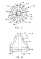
- a top view of the top section 38 of the porous liner is shown.
- a plurality of grooves or air channels 98 are formed in the top section, as shown.
- the grooves 98 are spaced apart and regularly directed from a topmost and centrally located hub section 100.
- the grooves 98 in the topmost portion are formed between triangular sections 102.
- the thickness of the top porous liner section 38 is equivalent to the thickness of wall section 104.
- the thickness of the walls is increased by the thickness of the wall segment shown as 106. Also as shown, the grooves 98 extend from the central hub 100, through the upper bell-shaped portion of porous liner section 38, and through the parallel and opposing sidewall portions 108.
- FIG. 4 a cross sectional view of the top section 38 of the porous liner of Fig. 3 is shown. Note that at the bottom of the section 38, a band-like bottom most portion of the wall portion 104 is cut out. As a result, the bottom 110 of the inner wall portion of wall portion 104 is shorter than and separated by a predetermined distance (see arrow 114) from the bottom 112 of the outer wall portion 106.
- the predetermined distance 114 between the bottoms 110 and 112 of wall sections 104 and 106, respectively, is dimensioned to provide the gap or radial groove 44 shown in Figs. 1 and 2, as will be described in greater detail below.
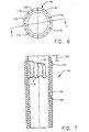
- FIGs. 6 and 7 A top view, and a side elevational view, are shown in Figs. 6 and 7, respectively, for the bottom section 42 of the porous liner, in this example.
- grooves or air channels 116 are formed or partially cut into the outside side wall portions 118, extending to an interior side wall portion 120, as shown.
- the interior side wall portion 120 extends beyond the top shoulder 122 of the outside side wall 118, by a predetermined distance indicated by arrow 124. Note that this predetermined distance 124 is made sufficiently greater that the predetermined distance 114, previously described for the extension of the outside wall segment 106 beyond the interior wall segment 104 of the top section 38 of the porous liner, for establishing the desired gap 44.
- the porous liner comprising the top section 38 that mates with a bottom section 42 is fabricated from a porous material.
- the size of the pores range from 5 to 20 microns, for example. Typically, the smaller the pore size used, the smaller the holes that can be detected in testing a condom 72 or other prophylactic articles for leaks. For the testing of a condom 72, in order to meet FDA requirements, the pore size is about 10 microns.
- the presently described porous liner 38, 42 were manufactured to the inventors' specifications by Porex Technologies of 500 Bohannon Road, Fairburn, GA 30281-2828, U.S.A. Note that porous liners of some other desired shape may be used for testing prophylactic articles such as gloves, for example.
- the thickness of the thinnest wall section of the porous liner should be at least 0.125 in. to withstand pressurization or inflation of a condom 72 under test to about 100 pounds per square inch.
- the top section 38 of the porous liner fits snugly within the bell shaped cavity 36 of the top housing section 2, the latter being configured to accomplish this.
- the bottom section 42 of the porous liner fits snugly within the cylindrical cavity 40 of the intermediate housing section 4, as shown, with the latter being configured to accomplish this.
- housing sections 2 and 4 are screwed together, the opposing surface of the interior wall portion 104 of the top section 38 is touching the top surface of the interior side wall portion 120 of the bottom section 42, as shown.
- the top and bottom sections 38 and 42 are configured to the shape of condoms 72 to be tested.
- the top section 38 is bell shaped
- the bottom section 42 is cylindrical with downwardly converging or tapered side portions.
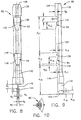
- Each finger 82 includes a rounded and tab-like topmost section 126 from which a centrally located rib 128 projects downward a relatively short distance, and terminates into a cam surface 92 including a flat surface portion 130 for about half of its length, terminating to a diverging sloped surface 132.
- the diverging surface 132 terminates at a tapered rib-like section 134, the latter terminating at another or second cam surface 96.
- the cam surface 96 similar to cam surface 92, but of different dimension, includes an upper flat portion 136, and a lower tapered diverging and outwardly slopping surface 138.
- the outwardly slopping surface 138 terminates at a relatively elongated flat surface 140, which in turn terminates to a relatively narrow foot member 142.
- the bottom of the foot member 142 includes a slightly widened portion 144. The configuration of the foot member 142 with a widened portion 144, permits air to flow around the foot 142 and through the center portion of the expandable condom holder 78, for inflating a condom 72 under test, as previously described. As shown in the top view of Fig.
- each expandable finger is configured to traverse an arc e of about 90°, or one quadrant.
- the elastomer member 80 is positioned around four of the fingers 82 for resiliently securing them together to form the column-like condom holder 78.
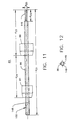
- the cam rod assembly 84 is shown.
- the cam rod 86 has a length d 21 of 7.06 in. (19 cm), in this example; a reduced stub-like top end portion 146 has a length d 22 of 0.569 in. (1,5 cm); and has a hollow core portion 148.
- the first cam section 88 is mounted upon the cam rod 86 with its bottom surface a distance d 23 of 2.625 inch from the tip of the reduced end portion 146 of cam rod 86.
- the second cam section 90 is rigidly mounted upon cam rod 86 at a distance d 24 of 3.25 in (8 cm) between its bottom surface and the bottom surface of the first cam section 88.
- the width d 25 of the reduced stub-like top end portion 146 is about 0.188 inch (0,5 cm).
- the top end of the cam rod 86 facing the end of the reduced top end portion 146 is shown in Fig. 12 to have a chamfer.
- a front elevational view of the first cam section 88 is shown, and a side elevational view thereof is shown in Fig. 13B.
- a threaded hole 150 is formed through the center of the cam section 88 for screwing onto a threaded outer portion 152 of cam rod 86 (see Fig. 11).
- the front of the first cam section 88 is square having a dimension d 26 of 0.607 inch (1,5 cm) diverging side portions extend rearward from the front face 154, and each has a maximum dimension d 27 of 0.759 inch (2 cm).
- the quarter inch threaded hole 150 is centered upon the front face 154.
- the tapered portion of can section 88 has a width d 28 of 0.25 inch (0,6 cm), and the overall length d 29 of this cam section 88 is 0.625 in. (1,6cm), in this example.
- the front face 158 is square have a dimension d 30 , in this example, of 0.544 inch (1,4 cm).
- the width of the tapered sides 160, which diverge towards the rear have a maximum dimension d 31 of 0.663 inch (1,7cm).
- the length d 32 of the rearward sloping side surfaces 160 is 0.25 in.
- the overall length of the second cam section 90 d 33 is 0.625 inch (1,6 cm) in this example.
- Other dimensions can be used, depending upon the application.
- a threaded hole 161 is centered upon the front face 158.
- the dimensions given for the cam rod assembly 84 components, and the expandable fingers 82, provide the necessary expansion of the condom holder 78, for permitting a typical condom 72 to be rolled off holder 78.
- bracket 8 has one end rigidly mounted via bolts 160 (only one is shown) to an upright frame member 162.
- the housing sections 2, 4, and 6 are rigidly secured over the expandable condom holder 78 carried on the movable platform 60, in this example.
- the movable platform 60 is rigidly mounted on the top of a bracket 164.
- an air cylinder 166 is rigidly secured to the bottom portion of the movable platform 60, and includes means (not shown) for connecting a control rod from the cylinder 166 to the cam rod 86, for selectively operating the air cylinder 166 to pull the cam rod 86 downward for moving cams section 88 and 90 to a position causing the expandable figures 82 to expand upon the elastomer sheet 80, for firmly securing a condom 72 to permit it to be rolled off via the rotating belt or brush assembly 168.
- the bracket 164 is rigidly connected to a bushing 170 mounted upon a linear slide rod 172 via bolts 175.
- the bottom of the bracket 164 is rigidly secured to a second air cylinder 174 via securing nuts 176.
- the securing nut 176 rigidly connects bracket 164 to a push rod 178 of air cylinder of 174.
- a cylinder mounting bracket 180 is secured at one end to air cylinder 174 via bolts 160, and at its other end to the frame member 162 via bolts 160, as shown.
- the air cylinder 174 is selectively actuated for moving the condom holder 78 up and down upon the linear slide rod 172. Accordingly, air cylinder 174 can be operated for pushing condom holder 78 into engagement with the porous liner sections 38 and 42, as previously described, for testing a condom 72. And after testing, air cylinder 174 can be operated for withdrawing condom holder 78 from the porous liner sections 38 and 42 to the position shown in Fig. 15.
- the rotating belt or brush assembly 168 comprises a rotating belt or brush 180, which can be selectively pushed against a condom 72 mounted on expandable condom holder 78, through means not shown for pushing actuating rod 182 portion toward the condom holder 78. Note that the belt or brush 180 moves in the direction of arrow 184, for rolling condoms 72 off of condom holder 78.
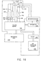
- a plurality of test apparatus is symbolically shown as porous liner shaped elements 186, each meant to incorporate the apparatus of Fig. 15, in this example.
- Air lines or air conduits 188 are connected between a valving matrix 190 and the air ports 54 of each one of the test apparatus 186, respectively.
- Other air lines or air conduits 192 are connected between the valving matrix 190 and air ports 28 of the respective testing apparatus 186.
- the air lines 192 are also connected to input ports of pressure transducers 194, respectively.
- the output ports of the pressure transducers 194 are individually connected for providing pressure signals to a microprocessor 196.
- a manometer 198 is connected to microprocessor 196 and valving matrix 190.
- An air pressure source 200 is connected through a filter 202 to valving matrix 190.
- the air pressure source 200 provides a plurality of different pressures via individual pressure lines (not shown) for test pressure, condom extraction, dust blow out, condom holder movement, condom holder expansion, porous liner expansion, and reject condom blow off, respectively.
- a reference tank 206 provides a stable pressure reference signal to the pressure transducers 194, and microprocessor 196. Control of this equipment in any of the modes of operation is effected by the microprocessor 196.
- Microprocessor 196 operates valves (not shown) within the valving matrix 190, so as to couple the test apparatus 186 to the air pressure source 200, and the manometer 198. Signals representing whether or not microprocessor 196 finds a leak in each of the condoms 72 under test are provided via individual test apparatus assembly 186, respectively.
- the pressure transducers 194 are used to measure the pressure within an associated air port 28 of the associated test apparatus 186, and to provide a corresponding pressure signal to microprocessor 196.
- the associated pressure transducer 194 is used to compare the pressure within air port 28 against the pressure within a reference tank 206, for obtaining a measure of the rate of change of air pressure within the associated air port 28.
- the manometer 198 is used for measuring the absolute pressure within a condom 72 under test.
- the filter 202 is used to ensure that pressurized air from the air pressure source 200 is free of contaminants before being delivered to the valves of the valving matrix 190.
- the microprocessor 196 is programmed to carry out the required testing sequences, and required reporting.
- the programming includes opening and closing appropriate ones of the valves of the valving matrix 190 at required times, processing signals representative of various measured pressures or rates of change in pressure, fault testing, and so forth.
- a typical testing cycle as will be described in greater detail below, is shown in Fig. 17.
- a condom 72 under test is inflated via microprocessor 196 operating valving matrix 190 to connect air pressure source 200 to an air port 54 of the associated test apparatus 186.
- a stabilization period T 2 is provided for stabilizing the pressure in the associated test apparatus 186.
- a test mode is entered over a time period T 3 for measuring the rate of change of pressure within the associated air port 28 of the test apparatus 186. If the rate of change of pressure over predetermined periods of time exceeds a predetermined value, condom 72 under test is rejected, otherwise it is accepted.
- the microprocessor 196 can further be programmed, for example, to conduct concurrent testing of three condoms 72, in this example, in a sequence where each one of the respective test apparatus 186 is in a different one of the three periods T 1 , T 2 , and T 3 of operation, respectively.
- the test apparatus and testing system can be designed to simultaneously test any desired number of condoms 72, to a practical limit, using the various embodiments of the present invention.
- the microprocessor 196 is programmed to automatically carry out the required steps.
- the first step is to position the condom holder 78 as shown in Fig. 15, but with the expandable condom holder 78 in its nonexpanded state as shown in Fig. 2.
- a condom 72 to be tested is then placed over the expandable condom holder 78.
- the next step is to operate air cylinder 174, in this example, for moving the expandable condom holder 78 into the porous liner 38, 42.
- air cylinder 174 in this example, for moving the expandable condom holder 78 into the porous liner 38, 42.
- a cam or other means can be used to provide the function of air cylinder 174.
- Sufficient force must be applied by air cylinder 174 to form an air tight seal between the metal seal ring 52 of the bottom housing section 6, the elastomer sheet 80, and the bottom of the condom 72, as shown in Fig. 2.
- the next step is to operate the valving matrix 190 for connecting the air pressure source 200 to the air port 54, while venting the air port 28 to the atmosphere, for initiating the first period T 1 , for inflating the condom 72 with a given air pressure while allowing the air space between the porous liner 38, 42 and housing sections 2, 4, and 6, respectively, to vent to the atmosphere.
- the inflated condom 72 now has its outside walls forced against the opposing inside walls of the porous liner 38, 42.
- the next step is to operate valving matrix 190 to seal or close off the associated air port 28 to isolate the space between the porous liner section 38, 42, and housing sections 2, 4, and 6, respectively, from the atmosphere.
- the next step is to retain the test apparatus in its last mode of operation for a second period of time T 2 sufficient to permit the air pressure in the spaces between the porous liner 38, 42, and housing sections 2, 4, and 6, respectively, to stabilize.
- a third time period T 3 is entered for measuring the rate of pressure increase in the space between the porous liner 38, 42, and housing sections 2, 4, and 6, respectively.
- This measurement is made by operating valving matrix 190 to maintain a given air pressure from air pressure source 200 to air port 58, while comparing the pressure signal from the associated pressure transducer 194 with the pressure of the reference tank 206. This is accomplished by measuring the pressure at the beginning of the period T 3 , and at the end of the period T 3 , and dividing the increase of pressure if any by the time T 3 .
- the microprocessor 196 next compares the measured rate of pressure increase against a predetermined standard value. If the measured rate of pressure increase over a predetermined period of time exceeds the predetermined acceptance value, the condom 72 is rejected, otherwise it is accepted.
- the valving matrix 190 is operated in the next step for connecting the associated air ports 54 and 28 of the test apparatus 186 to the atmosphere for venting air pressure from inside the condom 72 under test.
- the next step is to operate air cylinder 174 for withdrawing the expandable condom holder 78 with the condom 72 from the porous liner 38, 42 and associated housing 2, 4, and 6.
- the valving matrix 190 is also operated for injecting pressurized air from air source 200 into the associated air port 28, for substantially preventing the condom 72 from sticking to the inside wall surface of the porous liner sections 38, 42, thereby aiding in extraction of the condom 72 on the condom holder 78.
- the next step is to blow the rejected condom 72 off of the expandable condom holder 78, in this example. This is accomplished by extracting condom holder 78 from housing 2, 4, 6, followed by injecting pressurized air into port 54.
- the next step is to operate air cylinder 166 for pulling the cam rod assembly 84 downward or in a direction for moving the expandable fingers 82 away from one another to the expanded position as shown in Fig. 15. Note that in a practical system, this step may be carried out regardless of whether a condom 72 has been rejected and previously blow off the condom holder 78, or accepted and remains on the condom holder 78.
- the next step is to roll accepted condoms 72 off the expandable condom holder 78 by moving the rotating belt or brush 180 against the condom 72.
- the rolled condom 72 automatically pops off of the top of the condom holder 78, whereafter the condom 72 is retrieved for packaging
- the next step is to operate air cylinder 166 for moving the cam rod 86 upward to disengage the cam sections 88 and 90 from the expandable fingers 82, for returning the expandable condom holder 78 to its nonexpanded state.
- the elastomer sheet 80 acts as a return spring, for providing the force for moving the expandable fingers 82 towards one another as the cam sections 88 and 90 are disengaged therefrom.
- the next step is to operate the valving matrix 190 for applying high pressure air from air pressure source 200 to air port 28, for blowing out any powder that may have collected upon the inside surfaces of the porous liner sections 38, 42 from the condom 72 that had been tested.
- the last remaining step in the illustrated preferred cycle of operation is to operate the valving matrix 190 for connecting air ports 28 and 54 to the atmosphere, thereby venting the space between the porous liner sections 38, 42, and housing sections 2, 4, and 6, respectively, to the atmosphere.
- the manometer 198 can be used for determining whether the pressure within the condom is increasing at a predetermined rate, which if not obtained will result in the microprocessor 196 operating to reject the condom 72.
- the microprocessor 196 can further be programmed to keep track of the number of condoms 72 rejected during inflation periods, for determining whether the test apparatus 186 should be checked for proper operation if an excessive number of condom 72 are so rejected.
- the microprocessor 196 can be programmed to monitor the operation of the test system, by keeping track of the number of condoms 72 rejected and the number accepted by each test apparatus 186. If there are no rejects for a predetermined number X of tests or no acceptances for Y tests, the system is shut down for servicing of the test apparatus 186. Also, programming can provide that if there are no rejects made by the given test apparatus 186 for a predetermined number of tests or no acceptances for another predetermined number of tests, that the system should be shut down for servicing.
- Another modification that can be made includes the use of a tag gas for inflating a condom 72 instead of air, whereby instead of testing for increases of pressure in a region outside of the condom 72, a detector can be employed for detecting the presence of tag gas outside the condom 72 to detect a leak or hole in the condom 72.
- a tag gas and a rate of change of differential pressure can be employed at the same time for testing a condom 72.
- a low molecular weight gas such as Helium
- condoms have been used in illustrating various embodiments of the invention, many other prophylactic devices can be tested by the present embodiments of the invention, and the associated porous liner 38, 42 can be shaped as required.
- Another modification for the invention is to test a condom 72 by keeping the air port 58 of the bottom housing section open to the atmosphere, while drawing a vacuum at air port 28.
- the condom 72 will in effect be inflated and in this case pulled against the inside walls of the porous liner 38, 42. Leaks can then be detected by monitoring the decrease in vacuum within air port 28, or rate of increase of pressure therein, for detecting leaks in condom 72.
- the rate of change of pressure is compared against a standard or predetermined pressure for determining whether a condom 72 under test is to be accepted or rejected.
- the porous liner 38, 42 is in two sections because a tapered shape is required for testing tapered condoms, but the porous liner can be provided in one piece for testing non-tapered or straight walled condoms.
- the metal ring seal 52 can be replaced by an elastomeric inflatable seal, for example.
Landscapes
- Physics & Mathematics (AREA)
- General Physics & Mathematics (AREA)
- Orthopedics, Nursing, And Contraception (AREA)
- Examining Or Testing Airtightness (AREA)
- Materials For Medical Uses (AREA)
- Sampling And Sample Adjustment (AREA)
- Drilling And Boring (AREA)
- Separation Using Semi-Permeable Membranes (AREA)
- Chair Legs, Seat Parts, And Backrests (AREA)
- Aeration Devices For Treatment Of Activated Polluted Sludge (AREA)
Claims (13)
- System zum Testen einer Prophylaxevorrichtung (12) auf Löcher, das folgendes aufweist:Einen porösen hohlen Überzug (38, 42) mit einem inneren Hohlraum (70) der an die äußere Form der zu testenden Vorrichtung angepaßt ist;Rückhalteeinrichtungen (68,78) zum Zurückhalten eines wesentlichen Bereichs der zu testenden Vorrichtung in dem inneren Hohlraum (70) des Überzugs (38, 42); Einrichtungen (28, 58) zum Erzeugen eines vorgegebenen Differenzgasdrucks zwischen einem Raum in der Vorrichtung (72) und einem Raum (40) in der Nähe der äußeren Wände des porösen Überzugs (38, 42), wobei der Unterschied im Gasdruck bei der Vorrichtung (72) bewirkt, dass sich diese mit äußeren Wänden aufbläst, wobei sie gegen innere Wände des inneren Hohlraums (10) gedrückt oder gezogen wird; undEinrichtungen (194) zum Messen der Änderung des Differenzgasdrucks, zum Bestimmen ob Löcher in der Vorrichtung (72) vorhanden sind, sodass die Vorrichtung für ihre beabsichtigte Verwendung akzeptiert oder zurückgewiesen wird.
- System gemäß Patentanspruch 1, wobei die Einrichtung (28, 58) zum Erzeugen eines Differenzgasdrucks den Druck im Raum mit der zu testenden Vorrichtung (72) in Bezug auf den Atmosphärendruck genügend vergrößert, um die Vorrichtung auf einen vorgegebenen Druck aufzublasen.
- System nach Patentanspruch 1 oder 2, des weiteren aufweisend:Ein Gehäuse mit Oberteil (2), Boden (6) und Seitenabschnitten (4) und einem inneren Hohlraum (40), der der äußeren Form des Überzugs (38, 42) zum Zurückhalten des Überzugs darin angepaßt ist; und einen ersten Gasanschluß (28) an der Oberseite des Gehäuses (2, 6, 4), wobei der erste Gasanschluß (28) einen Gasdurchgang (32) aufweist, der sich in den Hohlraum (40) des Gehäuses (2, 6, 4) erstreckt, um Gas zu erlauben zwischen den Hohlraum (70) des Überzugs (38, 42) durch Poren des Überzugs (38, 42) und dem ersten Gasanschluß (28) zu strömen.
- System gemäß Patentanspruch 3, wobei der Überzug (38, 42) ferner aufweist:Mehrere von einander beabstandete Längsrillen (98) auf äußeren Wänden des Überzugs (38, 42), wobei die Rillen (98) sich von einem obersten Abschnitt (100) des Überzugs (38, 42) in der Nähe des ersten Gasanschluß (28) des Gehäuses (2, 6, 4) erstrecken, wobei der Überzug (38, 42) darin an dem untersten Abschnitten (42) des Überzugs installiert ist, um einen offenen Pfad für die Gasströmung zwischen dem ersten Anschluss (28) und einem Abschnitt einer Wand des Überzugs (38, 42) in der Nähe eines Lochs in der zu testenden Vorrichtung (72) an einer gegenüberliegenden Seite des Überzugwandabschnitts (38 oder 42) zur Verfügung zu stellen, wobei verhindert wird, dass das Gas von der Öffnung in der Vorrichtung (72) durch einen verschlungenen Pfad von Poren in der Länge des Überzugmaterials zwischen dem ersten Gasanschluss (28) und der Position der Öffnung durch die Vorrichtung (72) verhindert wird.
- System gemäß irgendeinem der voranstehenden Patentansprüche, wobei die Zurückhalteeinrichtungen (68 oder 78) folgendes aufweisen:Einen Halter (68 der 78) zum Zurückhalten der Vorrichtung darin;Gleiteinrichtungen (60), die mit dem Bodenabschnitt des Halters (68 oder 78) zum selektiven Bewegen des Halters (68 oder 78) in dem inneren Hohlraum (70) des Überzugs (38, 42) zum Testen der Vorrichtung (72) verbunden ist, oder zum Zurückziehen des Halters (68 oder 78) mit der Vorrichtung (72) von dem Überzug im Anschluss an das Testen der Vorrichtung.
- System gemäß Patentanspruch 5, wobei die Gleitvorrichtung (60) folgendes aufweist:Eine Plattform (60) mit einer Vertiefung (66) an einer oberen Fläche, die einen Bodenabschnitt des Halters (68 oder 78) zurück hält;eine erste Klammer (16 A) mit einem Ende, das steif an der Plattform (60) und an einem anderen Ende befestigt ist;einen linearen Gleitstab (172);eine Buchse (170), die gleitbar auf der Gleitstange (172) montiert ist, wobei das andere Ende der ersten Klammer steif mit der Buchse (170) verbunden ist;ein lang gestrecktes Tragelement (162);Einrichtungen zum Befestigen der linearen Gleitstange (172) an dem Tragelement (162) in beabstandeter aber paralleler Beziehung dazu;Einrichtungen (8, 10) zum Befestigen des Überzugs (38, 42) an dem Tragelement (162), um eine Eingangsöffnung des Überzugs (38, 42) über dem Halter (78) aufzuhängen; underste Antriebseinrichtungen (166), die von der ersten Trageinrichtung (162) und unter der Plattform (60) aufgehängt sind, wobei eine Druckstange der Antriebseinrichtung an einer Unterseite der Plattform (60) befestigt ist, wobei die erste Antriebseinrichtung (166) zum selektiven Bewegen der Plattform (60) in Richtung des porösen Überzugs (38, 42) zum Einführen des Halters (78) in den Überzug (38, 42) und zur Bewegung der Plattform (60) weg von dem Überzug (38, 42) zum Entfernen des Halters (78) von dem Überzug (38, 42) bewegbar ist.
- System gemäß Patentanspruch 6, wobei die Plattform (60) ferner einen zweiten Gasanschluß (Figuren 1 und 2) aufweist, der einen Gasdurchgang durch eine Wand der Plattform (60) aufweist, um es dem Gas zu ermöglichen, zwischen dem zweiten Gasanschluß und einem inneren Volumen der zu testenden Vorrichtung (72) zu strömen; und
wobei die Gasdruckdifferenz erzeugenden Einrichtungen (190) mit dem ersten und dem zweiten Gasanschluß (28, 58) verbunden sind. - System gemäß Patentanspruch 6 oder 7, was ferner folgendes aufweist:Der Halter (78) weist Einrichtungen (80) auf, die selektiv zum leichten Expandieren des Halters (78) betreibbar sind, um der Prophylaxevorrichtung zu erlauben, nach dem Test abgerollt und von dem Halter (78) des Überzugs (38, 42) entfernt zu werden.
- System gemäß Patentanspruch 8, welches ferner folgendes aufweist:Einrichtungen (180), die selektiv betätigbar sind, um die Vorrichtung (72) auf dem Halter (78) zum Eingriff zu bringen, zum automatischen Abrollen der Vorrichtung um diese von dem Halter (78) zu entfernen.
- System gemäß Patentanspruch 4, welches dafür ausgelegt ist, um Kondome auf Löcher zu testen, wobei der Überzug (38, 42) ferner aufweist:einen unabhängigen oberen Abschnitt (38), der an die Form des oberen Abschnittes des Kondoms angepaßt ist; undeinen unabhängigen Bodenabschnitt (42) der an die Form des verbleibenen unteren Abschnitts des Kondoms angepaßt ist, wobei der Bodenabschnitt (42) einen obersten umlaufenden Schulterabschnitt (122) aufweist, der so ausgelegt ist, um mit einem untersten umlaufenden Schulterabschnitt (112) des oberen Abschnitts (38) verbunden zu werden, um den Überzug (38, 42) mit einer im wesentlichen kontinuierlichen inneren Wand zu bilden.
- System gemäß Patentanspruch 10, wobei der Überzug (38, 42) ferner die obere Schulter (122) des Bodenabschnitts (42) aufweist, die einen sich nach oben erstreckenden inneren Wandabschnitt mit einer Oberkante zum Anstoßen gegen eine Bodenkante (110) einer Innenwand des oberen Abschnitts (38) aufweist, wobei der obere Abschnitt (38) ferner einen sich nach unten erstreckenden äußeren Wandabschnitt (112) aufweist, der überlappt aber in der Länge kürzer als der innere Wandabschnitt des Bodenabschnitts (42) ist, wodurch ein Spalt oder kreisförmiger Kanal zwischen den äußeren Wandabschnitten der oberen oder Bodenabschnitte (38 und 42) zur Verfügung gestellt wird, wodurch das Erfordernis des Ausrichtens der Längsrillen des oberen und Bodenabschnitts (38 und 42) vermieden wird, um einen offenen Durchgang für Gas dazwischen zur Verfügung zu stellen.
- System gemäß Patentanspruch 11, wobei das Gehäuse (2, 4, 6) ferner folgendes aufweist:einen oberen Abschnitt (2) zum Zurückhalten des oberen Abschnitts (38) des Überzugs darin, wobei der erste Gasanschluß (28) in dem oberen Abschnitt (38) des Gehäuses ist;einen Zwischenabschnitt (4) zum Zurückhalten des Bodenabschnitts (42) des Überzugs (38, 42) darin;einen Bodenabschnitt (6), der einen inneren Hohlraum (46) aufweist, der sich in einen inneren Hohlraum (40) des Zwischenabschnitts (4) öffnet, wobei der innere Hohlraum (40) des Zwischenabschnitts (6) sich in einen inneren Hohlraum (32) des oberen Abschnitts (2) öffnet;Einrichtungen (12) zum Verbinden des oberen Abschnitts (2) mit dem Zwischenabschnitt (4) mit einer gasdichten Dichtung (18) dazwischen; undEinrichtungen (20) zum Verbinden des Zwischenabschnitts (4) mit dem Bodenabschnitt (6) mit einer gasdichten Dichtung (26) dazwischen.
- System gemäß Patentanspruch 5, welches angeordnet ist, um Kondome auf Löcher zu testen, welches ferner folgendes aufweist:wobei der Halter (78) ferner einen Gasdurchgang (76) zum Durchlassen von Gasströmung von dem zweiten Gasanschluß (54) des Gehäuses (2, 4, 6) durch einen offenen Zentralabschnitt (76) des Halters (78) und in das Kondom (72) zum Aufblasen des Kondoms nach dem Halter (78) aufweist, wobei das Kondom in den Überzieher (38, 42) in dem Gehäuse (2, 4, 6) eingeführt ist.Einrichtungen (52) zum Vorsehen einer gasdichten Dichtung zwischen dem untersten Abschnitt (6) der Innenwand des Gehäuses (2, 4, 6), dem Kondoms (72) und dem Halter (78); und
Applications Claiming Priority (2)
| Application Number | Priority Date | Filing Date | Title |
|---|---|---|---|
| US08/356,497 US5517849A (en) | 1994-12-15 | 1994-12-15 | Apparatus and method including porous liner for testing for holes in prophylactic devices |
| US356497 | 1994-12-15 |
Publications (3)
| Publication Number | Publication Date |
|---|---|
| EP0717277A2 EP0717277A2 (de) | 1996-06-19 |
| EP0717277A3 EP0717277A3 (de) | 1997-07-16 |
| EP0717277B1 true EP0717277B1 (de) | 2003-08-27 |
Family
ID=23401686
Family Applications (1)
| Application Number | Title | Priority Date | Filing Date |
|---|---|---|---|
| EP95304609A Expired - Lifetime EP0717277B1 (de) | 1994-12-15 | 1995-06-29 | Überprüfen einer Prophylaxevorrichtung auf Löcher mit einem porösen hohlen Einsatzstück |
Country Status (7)
| Country | Link |
|---|---|
| US (1) | US5517849A (de) |
| EP (1) | EP0717277B1 (de) |
| JP (1) | JP3559634B2 (de) |
| AT (1) | ATE248359T1 (de) |
| AU (1) | AU695085B2 (de) |
| CA (1) | CA2151983C (de) |
| DE (1) | DE69531595D1 (de) |
Families Citing this family (11)
| Publication number | Priority date | Publication date | Assignee | Title |
|---|---|---|---|---|
| WO1999006810A1 (en) * | 1997-08-01 | 1999-02-11 | Lrc Products Ltd. | Apparatus and method for automatically electronically testing condoms |
| US6164122A (en) * | 1999-04-21 | 2000-12-26 | Carter-Wallace, Inc. | System and method including multiple test chambers for automated testing for holes in prophylactic device |
| US6611149B1 (en) | 2002-12-23 | 2003-08-26 | Agri Dynamics, Inc. | Condom nipple testing apparatus |
| US7467717B2 (en) | 2005-12-23 | 2008-12-23 | Whitten James R | Failed roll condom removal apparatus |
| JP2010151548A (ja) * | 2008-12-24 | 2010-07-08 | Fujitsu Ltd | 気密性検査方法および気密性検査用部材 |
| CN104198267B (zh) * | 2014-06-26 | 2017-04-19 | 北京建筑大学 | 舱外航天服手套手腕运动寿命实验装置 |
| CN110279510B (zh) * | 2015-07-05 | 2021-11-16 | 大庆元子科技开发有限公司 | 一种安全套 |
| CN106269550B (zh) * | 2016-11-02 | 2018-08-14 | 石河子大学 | 一种红枣输送翻转装置 |
| CN109030211B (zh) * | 2018-08-06 | 2023-12-05 | 江苏科技大学 | 一种多功能组合拉伸夹具及其使用方法 |
| CN110017952B (zh) * | 2019-03-15 | 2020-09-08 | 王珍海 | 一种安全套孔洞漏气检测装置 |
| WO2021142404A1 (en) * | 2020-01-11 | 2021-07-15 | Hydroglyde Coatings Llc | Devices and methods for testing interfacial properties |
Family Cites Families (29)
| Publication number | Priority date | Publication date | Assignee | Title |
|---|---|---|---|---|
| US2126434A (en) * | 1937-08-19 | 1938-08-09 | Kenneth S Vosbury | Glove testing device |
| US2370945A (en) * | 1944-08-10 | 1945-03-06 | James J Fields | Device for testing rubber gloves |
| US2567926A (en) * | 1946-03-01 | 1951-09-18 | Milton S Dunkelberger | Tubular supporting member |
| US2855926A (en) * | 1955-11-15 | 1958-10-14 | Oxy O Meter Inc | Coin actuated oxygen dispensing machine |
| US2855777A (en) * | 1956-02-03 | 1958-10-14 | Moore Products Co | Vacuum leak testing apparatus |
| US3177704A (en) * | 1962-08-28 | 1965-04-13 | Robert H Stange | Leak testing method |
| US3315519A (en) * | 1964-04-13 | 1967-04-25 | American Sterilizer Co | Surgical glove leak tester |
| US3389811A (en) * | 1965-06-29 | 1968-06-25 | Frank Corp Alan I W | Mechanism for handling and testing containers |
| AU449169B2 (en) * | 1968-10-23 | 1974-05-16 | Owens-Illinois, Inc | Leak detector |
| US3667862A (en) * | 1970-12-09 | 1972-06-06 | Boeing Co | Blade inspection system and method |
| BE795542A (fr) * | 1972-02-18 | 1973-06-18 | Dynamit Nobel Ag | Procede et dispositif pour controler sous vide l'etancheite des cordons de soudure des bandes en matiere plastique |
| US3991604A (en) * | 1975-06-09 | 1976-11-16 | Parke, Davis & Company | Work fixture and testing method |
| US3992766A (en) * | 1975-08-26 | 1976-11-23 | Youngs Rubber Corporation | Apparatus for processing elastic articles |
| US4118972A (en) * | 1977-08-31 | 1978-10-10 | Container Corporation Of America | Apparatus for detecting leaks in composite packages |
| US4206631A (en) * | 1978-06-02 | 1980-06-10 | Batavian Rubber Company Limited | Inflatable product testing |
| SU1182326A1 (ru) * | 1984-04-28 | 1985-09-30 | Уфимское моторостроительное производственное объединение | Способ испытани полых крупногабаритных изделий на прочность и герметичность |
| US4683745A (en) * | 1986-08-28 | 1987-08-04 | Westvaco Corporation | Cannister seal integrity tester |
| US4875358A (en) * | 1987-05-21 | 1989-10-24 | Stephan Marsh | Preparation of condoms by the user |
| US4954309A (en) * | 1988-01-27 | 1990-09-04 | Apex Medical Technologies, Inc. | Method of forming a polymeric casing with textured surface |
| US4855169A (en) * | 1988-01-27 | 1989-08-08 | Apex Medical Technologies, Inc. | Prophylactic sheath with augmented border |
| US5073482A (en) * | 1988-06-21 | 1991-12-17 | Epitope, Inc. | Elastic barrier permeability testing device and method of use |
| AT393198B (de) * | 1989-03-13 | 1991-08-26 | Haas Franz Waffelmasch | Waffelteig, gebackenem backteig oder dergleichen |
| US5192256A (en) * | 1991-01-22 | 1993-03-09 | Ryan William T | Swim exercise or training apparatus |
| US5129256A (en) * | 1991-03-27 | 1992-07-14 | Lrc Products, Ltd. | Method and apparatus for leak testing of condoms by pressure differential |
| GB9123880D0 (en) * | 1991-11-09 | 1992-01-02 | Gore W L & Ass Uk | Leak testing |
| US5255558A (en) * | 1992-05-21 | 1993-10-26 | Hamilton Terry W | Method and device for testing condoms |
| US5327775A (en) * | 1992-10-27 | 1994-07-12 | Yakov Epshteyn | Condom tester and applicator |
| FR2700390B1 (fr) * | 1993-01-08 | 1995-04-14 | Elmetherm | Procédé et dispositif de contrôle de l'étanchéité d'une enveloppe déformable, notamment d'un préservatif. |
| US5438861A (en) * | 1994-07-19 | 1995-08-08 | Carter-Wallace, Inc. | Apparatus and method for testing for holes in a prophylactic device |
-
1994
- 1994-12-15 US US08/356,497 patent/US5517849A/en not_active Expired - Lifetime
-
1995
- 1995-06-16 CA CA002151983A patent/CA2151983C/en not_active Expired - Fee Related
- 1995-06-29 AT AT95304609T patent/ATE248359T1/de not_active IP Right Cessation
- 1995-06-29 DE DE69531595T patent/DE69531595D1/de not_active Expired - Lifetime
- 1995-06-29 EP EP95304609A patent/EP0717277B1/de not_active Expired - Lifetime
- 1995-07-06 AU AU24872/95A patent/AU695085B2/en not_active Ceased
- 1995-12-15 JP JP32774095A patent/JP3559634B2/ja not_active Expired - Fee Related
Also Published As
| Publication number | Publication date |
|---|---|
| JP3559634B2 (ja) | 2004-09-02 |
| DE69531595D1 (de) | 2003-10-02 |
| EP0717277A2 (de) | 1996-06-19 |
| AU2487295A (en) | 1996-06-20 |
| ATE248359T1 (de) | 2003-09-15 |
| JPH08233681A (ja) | 1996-09-13 |
| AU695085B2 (en) | 1998-08-06 |
| EP0717277A3 (de) | 1997-07-16 |
| US5517849A (en) | 1996-05-21 |
| CA2151983A1 (en) | 1996-06-16 |
| CA2151983C (en) | 2000-04-18 |
Similar Documents
| Publication | Publication Date | Title |
|---|---|---|
| EP0717277B1 (de) | Überprüfen einer Prophylaxevorrichtung auf Löcher mit einem porösen hohlen Einsatzstück | |
| US4754638A (en) | Apparatus and method for leak testing automotive wheel rims | |
| EP0579783B1 (de) | Testen von hüllen, insbesondere kondomen, auf undichtigkeiten durch druckunterschiede | |
| KR102448158B1 (ko) | 컨테이너의 내부 공간에서 백을 형성 및/또는 시험하기 위한 방법 | |
| CN112840192B (zh) | 用于检验线缆密封性的检验方法以及用于执行该方法的密封性检验装置 | |
| US3991604A (en) | Work fixture and testing method | |
| JPS5837495B2 (ja) | 洩れの検査方法及び装置 | |
| CN108279092A (zh) | 气密性检测装置、系统和检测方法 | |
| US6164122A (en) | System and method including multiple test chambers for automated testing for holes in prophylactic device | |
| US5097697A (en) | Method and apparatus for airburst testing condoms and the like | |
| CN109655213A (zh) | 一种手套漏气检测装置及其工作方法 | |
| EP0693678B1 (de) | Dorn mit unterschiedlichen Poren zur Dichtheitsprüfung prophylaktischer Artikel | |
| CN215115054U (zh) | 一种真空环境下密封涂层表面性能测试装置 | |
| US4010877A (en) | Work fixture and folding method | |
| US3955406A (en) | Non-destructive hardness testing of articles such as cigarettes | |
| KR20180000832A (ko) | 이중 브로우 용기 검사장치 | |
| CN108287042A (zh) | 泄漏检测装置及泄漏检测方法 | |
| CN206515021U (zh) | 用于密封件的泄漏检测装置 | |
| US2833141A (en) | Apparatus and system for leak testing | |
| CN212410000U (zh) | 一种管道气密性检测装置 | |
| CN217355949U (zh) | 内胀式管道端部密封连接装置 | |
| CN207423464U (zh) | 空调单向阀检测设备 | |
| CN215338741U (zh) | 一种耐磨阀用检测装置 | |
| CN120427202A (zh) | 一种氧气阀门气密测试装置及气密测试方法 | |
| CN120102038A (zh) | 一种瓶盖气密性检测装置 |
Legal Events
| Date | Code | Title | Description |
|---|---|---|---|
| PUAI | Public reference made under article 153(3) epc to a published international application that has entered the european phase |
Free format text: ORIGINAL CODE: 0009012 |
|
| AK | Designated contracting states |
Kind code of ref document: A2 Designated state(s): AT BE CH DE DK ES FR GB GR IE IT LI LU MC NL PT SE |
|
| PUAL | Search report despatched |
Free format text: ORIGINAL CODE: 0009013 |
|
| AK | Designated contracting states |
Kind code of ref document: A3 Designated state(s): AT BE CH DE DK ES FR GB GR IE IT LI LU MC NL PT SE |
|
| 17P | Request for examination filed |
Effective date: 19970830 |
|
| 17Q | First examination report despatched |
Effective date: 19990428 |
|
| RAP1 | Party data changed (applicant data changed or rights of an application transferred) |
Owner name: ARMKELL LLC |
|
| GRAH | Despatch of communication of intention to grant a patent |
Free format text: ORIGINAL CODE: EPIDOS IGRA |
|
| RTI1 | Title (correction) |
Free format text: TESTING FOR HOLES IN A PROPHYLACTIC DEVICE WITH A POROUS HOLLOW LINER. |
|
| GRAS | Grant fee paid |
Free format text: ORIGINAL CODE: EPIDOSNIGR3 |
|
| GRAA | (expected) grant |
Free format text: ORIGINAL CODE: 0009210 |
|
| AK | Designated contracting states |
Designated state(s): AT BE CH DE DK ES FR GB GR IE IT LI LU MC NL PT SE |
|
| PG25 | Lapsed in a contracting state [announced via postgrant information from national office to epo] |
Ref country code: NL Free format text: LAPSE BECAUSE OF FAILURE TO SUBMIT A TRANSLATION OF THE DESCRIPTION OR TO PAY THE FEE WITHIN THE PRESCRIBED TIME-LIMIT Effective date: 20030827 Ref country code: LI Free format text: LAPSE BECAUSE OF FAILURE TO SUBMIT A TRANSLATION OF THE DESCRIPTION OR TO PAY THE FEE WITHIN THE PRESCRIBED TIME-LIMIT Effective date: 20030827 Ref country code: IT Free format text: LAPSE BECAUSE OF FAILURE TO SUBMIT A TRANSLATION OF THE DESCRIPTION OR TO PAY THE FEE WITHIN THE PRE;WARNING: LAPSES OF ITALIAN PATENTS WITH EFFECTIVE DATE BEFORE 2007 MAY HAVE OCCURRED AT ANY TIME BEFORE 2007. THE CORRECT EFFECTIVE DATE MAY BE DIFFERENT FROM THE ONE RECORDED.SCRIBED TIME-LIMIT Effective date: 20030827 Ref country code: FR Free format text: LAPSE BECAUSE OF FAILURE TO SUBMIT A TRANSLATION OF THE DESCRIPTION OR TO PAY THE FEE WITHIN THE PRESCRIBED TIME-LIMIT Effective date: 20030827 Ref country code: CH Free format text: LAPSE BECAUSE OF FAILURE TO SUBMIT A TRANSLATION OF THE DESCRIPTION OR TO PAY THE FEE WITHIN THE PRESCRIBED TIME-LIMIT Effective date: 20030827 Ref country code: BE Free format text: LAPSE BECAUSE OF FAILURE TO SUBMIT A TRANSLATION OF THE DESCRIPTION OR TO PAY THE FEE WITHIN THE PRESCRIBED TIME-LIMIT Effective date: 20030827 Ref country code: AT Free format text: LAPSE BECAUSE OF FAILURE TO SUBMIT A TRANSLATION OF THE DESCRIPTION OR TO PAY THE FEE WITHIN THE PRESCRIBED TIME-LIMIT Effective date: 20030827 |
|
| REG | Reference to a national code |
Ref country code: GB Ref legal event code: FG4D |
|
| REG | Reference to a national code |
Ref country code: CH Ref legal event code: EP |
|
| REG | Reference to a national code |
Ref country code: IE Ref legal event code: FG4D |
|
| REF | Corresponds to: |
Ref document number: 69531595 Country of ref document: DE Date of ref document: 20031002 Kind code of ref document: P |
|
| PG25 | Lapsed in a contracting state [announced via postgrant information from national office to epo] |
Ref country code: SE Free format text: LAPSE BECAUSE OF FAILURE TO SUBMIT A TRANSLATION OF THE DESCRIPTION OR TO PAY THE FEE WITHIN THE PRESCRIBED TIME-LIMIT Effective date: 20031127 Ref country code: GR Free format text: LAPSE BECAUSE OF FAILURE TO SUBMIT A TRANSLATION OF THE DESCRIPTION OR TO PAY THE FEE WITHIN THE PRESCRIBED TIME-LIMIT Effective date: 20031127 Ref country code: DK Free format text: LAPSE BECAUSE OF FAILURE TO SUBMIT A TRANSLATION OF THE DESCRIPTION OR TO PAY THE FEE WITHIN THE PRESCRIBED TIME-LIMIT Effective date: 20031127 |
|
| PG25 | Lapsed in a contracting state [announced via postgrant information from national office to epo] |
Ref country code: DE Free format text: LAPSE BECAUSE OF FAILURE TO SUBMIT A TRANSLATION OF THE DESCRIPTION OR TO PAY THE FEE WITHIN THE PRESCRIBED TIME-LIMIT Effective date: 20031128 |
|
| PG25 | Lapsed in a contracting state [announced via postgrant information from national office to epo] |
Ref country code: ES Free format text: LAPSE BECAUSE OF FAILURE TO SUBMIT A TRANSLATION OF THE DESCRIPTION OR TO PAY THE FEE WITHIN THE PRESCRIBED TIME-LIMIT Effective date: 20031208 |
|
| PG25 | Lapsed in a contracting state [announced via postgrant information from national office to epo] |
Ref country code: PT Free format text: LAPSE BECAUSE OF FAILURE TO SUBMIT A TRANSLATION OF THE DESCRIPTION OR TO PAY THE FEE WITHIN THE PRESCRIBED TIME-LIMIT Effective date: 20040127 |
|
| NLV1 | Nl: lapsed or annulled due to failure to fulfill the requirements of art. 29p and 29m of the patents act | ||
| REG | Reference to a national code |
Ref country code: CH Ref legal event code: PL |
|
| PGFP | Annual fee paid to national office [announced via postgrant information from national office to epo] |
Ref country code: FR Payment date: 20040618 Year of fee payment: 10 |
|
| PG25 | Lapsed in a contracting state [announced via postgrant information from national office to epo] |
Ref country code: LU Free format text: LAPSE BECAUSE OF NON-PAYMENT OF DUE FEES Effective date: 20040629 Ref country code: IE Free format text: LAPSE BECAUSE OF NON-PAYMENT OF DUE FEES Effective date: 20040629 |
|
| PG25 | Lapsed in a contracting state [announced via postgrant information from national office to epo] |
Ref country code: MC Free format text: LAPSE BECAUSE OF NON-PAYMENT OF DUE FEES Effective date: 20040630 |
|
| PLBE | No opposition filed within time limit |
Free format text: ORIGINAL CODE: 0009261 |
|
| STAA | Information on the status of an ep patent application or granted ep patent |
Free format text: STATUS: NO OPPOSITION FILED WITHIN TIME LIMIT |
|
| 26N | No opposition filed |
Effective date: 20040528 |
|
| EN | Fr: translation not filed | ||
| REG | Reference to a national code |
Ref country code: IE Ref legal event code: MM4A |
|
| PGFP | Annual fee paid to national office [announced via postgrant information from national office to epo] |
Ref country code: GB Payment date: 20060626 Year of fee payment: 12 |
|
| GBPC | Gb: european patent ceased through non-payment of renewal fee |
Effective date: 20070629 |
|
| PG25 | Lapsed in a contracting state [announced via postgrant information from national office to epo] |
Ref country code: GB Free format text: LAPSE BECAUSE OF NON-PAYMENT OF DUE FEES Effective date: 20070629 |