EP0715542B1 - Verfahren zur vermeidung von sedimentationen - Google Patents
Verfahren zur vermeidung von sedimentationen Download PDFInfo
- Publication number
- EP0715542B1 EP0715542B1 EP94926197A EP94926197A EP0715542B1 EP 0715542 B1 EP0715542 B1 EP 0715542B1 EP 94926197 A EP94926197 A EP 94926197A EP 94926197 A EP94926197 A EP 94926197A EP 0715542 B1 EP0715542 B1 EP 0715542B1
- Authority
- EP
- European Patent Office
- Prior art keywords
- disturbance
- strings
- zone
- crude oil
- disturbing
- Prior art date
- Legal status (The legal status is an assumption and is not a legal conclusion. Google has not performed a legal analysis and makes no representation as to the accuracy of the status listed.)
- Expired - Lifetime
Links
- 238000000034 method Methods 0.000 title claims abstract description 46
- 238000004062 sedimentation Methods 0.000 title claims description 18
- 230000008569 process Effects 0.000 title abstract description 11
- 239000010779 crude oil Substances 0.000 claims abstract description 83
- 238000001556 precipitation Methods 0.000 claims abstract description 36
- 239000002243 precursor Substances 0.000 claims abstract description 19
- 230000015572 biosynthetic process Effects 0.000 claims abstract description 17
- 239000000203 mixture Substances 0.000 claims abstract description 17
- 230000008719 thickening Effects 0.000 claims abstract description 12
- 230000036961 partial effect Effects 0.000 claims abstract description 6
- 239000012528 membrane Substances 0.000 claims description 28
- 239000003921 oil Substances 0.000 claims description 28
- 238000003860 storage Methods 0.000 claims description 19
- 238000007667 floating Methods 0.000 claims description 14
- 239000007788 liquid Substances 0.000 claims description 13
- 239000007791 liquid phase Substances 0.000 claims description 10
- 229910000831 Steel Inorganic materials 0.000 claims description 8
- 239000010959 steel Substances 0.000 claims description 8
- 230000010355 oscillation Effects 0.000 claims description 6
- 239000004033 plastic Substances 0.000 claims description 6
- 229920003023 plastic Polymers 0.000 claims description 6
- 239000002184 metal Substances 0.000 claims description 4
- 229910052751 metal Inorganic materials 0.000 claims description 4
- 229910000851 Alloy steel Inorganic materials 0.000 claims description 2
- 229910000906 Bronze Inorganic materials 0.000 claims description 2
- 239000010974 bronze Substances 0.000 claims description 2
- KUNSUQLRTQLHQQ-UHFFFAOYSA-N copper tin Chemical compound [Cu].[Sn] KUNSUQLRTQLHQQ-UHFFFAOYSA-N 0.000 claims description 2
- 230000000284 resting effect Effects 0.000 claims 3
- 239000012530 fluid Substances 0.000 claims 2
- 238000010009 beating Methods 0.000 claims 1
- 238000009833 condensation Methods 0.000 claims 1
- 230000005494 condensation Effects 0.000 claims 1
- 230000009969 flowable effect Effects 0.000 claims 1
- 239000013049 sediment Substances 0.000 abstract description 28
- 238000009434 installation Methods 0.000 abstract description 3
- 239000003348 petrochemical agent Substances 0.000 abstract 1
- 230000001376 precipitating effect Effects 0.000 abstract 1
- 230000005284 excitation Effects 0.000 description 38
- 239000010802 sludge Substances 0.000 description 28
- 230000000694 effects Effects 0.000 description 13
- 230000002452 interceptive effect Effects 0.000 description 12
- 239000012535 impurity Substances 0.000 description 11
- 230000033001 locomotion Effects 0.000 description 11
- 239000000463 material Substances 0.000 description 9
- 229930195733 hydrocarbon Natural products 0.000 description 8
- 150000002430 hydrocarbons Chemical class 0.000 description 8
- 230000008901 benefit Effects 0.000 description 6
- 238000004140 cleaning Methods 0.000 description 6
- 230000007547 defect Effects 0.000 description 6
- 238000012545 processing Methods 0.000 description 6
- 239000000126 substance Substances 0.000 description 6
- 239000004215 Carbon black (E152) Substances 0.000 description 5
- 239000000243 solution Substances 0.000 description 5
- 238000013461 design Methods 0.000 description 4
- XLYOFNOQVPJJNP-UHFFFAOYSA-N water Substances O XLYOFNOQVPJJNP-UHFFFAOYSA-N 0.000 description 4
- 238000013459 approach Methods 0.000 description 3
- 230000005484 gravity Effects 0.000 description 3
- 230000002265 prevention Effects 0.000 description 3
- 238000011084 recovery Methods 0.000 description 3
- 150000003839 salts Chemical class 0.000 description 3
- 239000004576 sand Substances 0.000 description 3
- 230000003068 static effect Effects 0.000 description 3
- 238000003756 stirring Methods 0.000 description 3
- 230000008859 change Effects 0.000 description 2
- 238000005345 coagulation Methods 0.000 description 2
- 230000015271 coagulation Effects 0.000 description 2
- 238000010276 construction Methods 0.000 description 2
- 239000000839 emulsion Substances 0.000 description 2
- 230000007613 environmental effect Effects 0.000 description 2
- 230000001970 hydrokinetic effect Effects 0.000 description 2
- 230000003993 interaction Effects 0.000 description 2
- 238000012423 maintenance Methods 0.000 description 2
- 230000007246 mechanism Effects 0.000 description 2
- 239000002245 particle Substances 0.000 description 2
- 238000006116 polymerization reaction Methods 0.000 description 2
- 230000009467 reduction Effects 0.000 description 2
- 230000002829 reductive effect Effects 0.000 description 2
- 238000000926 separation method Methods 0.000 description 2
- 239000001993 wax Substances 0.000 description 2
- 241000881711 Acipenser sturio Species 0.000 description 1
- RYGMFSIKBFXOCR-UHFFFAOYSA-N Copper Chemical compound [Cu] RYGMFSIKBFXOCR-UHFFFAOYSA-N 0.000 description 1
- 206010013911 Dysgeusia Diseases 0.000 description 1
- VYPSYNLAJGMNEJ-UHFFFAOYSA-N Silicium dioxide Chemical compound O=[Si]=O VYPSYNLAJGMNEJ-UHFFFAOYSA-N 0.000 description 1
- 229910045601 alloy Inorganic materials 0.000 description 1
- 239000000956 alloy Substances 0.000 description 1
- 230000009286 beneficial effect Effects 0.000 description 1
- 230000005540 biological transmission Effects 0.000 description 1
- 238000004364 calculation method Methods 0.000 description 1
- 238000006243 chemical reaction Methods 0.000 description 1
- 239000003795 chemical substances by application Substances 0.000 description 1
- 239000000356 contaminant Substances 0.000 description 1
- 238000011109 contamination Methods 0.000 description 1
- 229910052802 copper Inorganic materials 0.000 description 1
- 239000010949 copper Substances 0.000 description 1
- 238000005520 cutting process Methods 0.000 description 1
- 230000007423 decrease Effects 0.000 description 1
- 230000003111 delayed effect Effects 0.000 description 1
- 230000001419 dependent effect Effects 0.000 description 1
- 238000010790 dilution Methods 0.000 description 1
- 239000012895 dilution Substances 0.000 description 1
- 238000009826 distribution Methods 0.000 description 1
- 238000005553 drilling Methods 0.000 description 1
- 238000005516 engineering process Methods 0.000 description 1
- 238000003912 environmental pollution Methods 0.000 description 1
- 239000002360 explosive Substances 0.000 description 1
- 238000002347 injection Methods 0.000 description 1
- 239000007924 injection Substances 0.000 description 1
- JEIPFZHSYJVQDO-UHFFFAOYSA-N iron(III) oxide Inorganic materials O=[Fe]O[Fe]=O JEIPFZHSYJVQDO-UHFFFAOYSA-N 0.000 description 1
- 230000001788 irregular Effects 0.000 description 1
- 230000007257 malfunction Effects 0.000 description 1
- 238000004519 manufacturing process Methods 0.000 description 1
- 238000004137 mechanical activation Methods 0.000 description 1
- 150000002739 metals Chemical class 0.000 description 1
- 238000002156 mixing Methods 0.000 description 1
- 238000005457 optimization Methods 0.000 description 1
- -1 paraffins Chemical class 0.000 description 1
- 239000012071 phase Substances 0.000 description 1
- 230000010363 phase shift Effects 0.000 description 1
- 230000003449 preventive effect Effects 0.000 description 1
- 238000005086 pumping Methods 0.000 description 1
- 230000001105 regulatory effect Effects 0.000 description 1
- 230000002040 relaxant effect Effects 0.000 description 1
- 238000012958 reprocessing Methods 0.000 description 1
- 230000000630 rising effect Effects 0.000 description 1
- 239000002689 soil Substances 0.000 description 1
- 239000007787 solid Substances 0.000 description 1
- 150000003464 sulfur compounds Chemical class 0.000 description 1
- 230000009974 thixotropic effect Effects 0.000 description 1
- 238000012549 training Methods 0.000 description 1
- 238000002604 ultrasonography Methods 0.000 description 1
Images


Classifications
-
- B—PERFORMING OPERATIONS; TRANSPORTING
- B08—CLEANING
- B08B—CLEANING IN GENERAL; PREVENTION OF FOULING IN GENERAL
- B08B17/00—Methods preventing fouling
-
- B—PERFORMING OPERATIONS; TRANSPORTING
- B01—PHYSICAL OR CHEMICAL PROCESSES OR APPARATUS IN GENERAL
- B01F—MIXING, e.g. DISSOLVING, EMULSIFYING OR DISPERSING
- B01F31/00—Mixers with shaking, oscillating, or vibrating mechanisms
- B01F31/44—Mixers with shaking, oscillating, or vibrating mechanisms with stirrers performing an oscillatory, vibratory or shaking movement
-
- B—PERFORMING OPERATIONS; TRANSPORTING
- B01—PHYSICAL OR CHEMICAL PROCESSES OR APPARATUS IN GENERAL
- B01F—MIXING, e.g. DISSOLVING, EMULSIFYING OR DISPERSING
- B01F33/00—Other mixers; Mixing plants; Combinations of mixers
- B01F33/40—Mixers using gas or liquid agitation, e.g. with air supply tubes
- B01F33/403—Mixers using gas or liquid agitation, e.g. with air supply tubes for mixing liquids
Definitions
- the invention relates to a method for avoiding sedimentation Liquid phases or a thickening of liquid phases or liquid mixtures such as oils, crude oil, refinery products and petrochemical products, which successively predominantly on the floor especially of storage containers settle, settling in such storage containers before the start of sedimentation forms a precursor in the form of a condensing precipitation zone, from which a thickening is initialized and successively in sedimentation and / or thickening passes.
- the liquid phase of crude oil is mainly made up of hydrocarbons such as paraffins, aromatics and naphthenic mixture, which at their promotion but also of non-hydrocarbons or so-called Impurities such as mud, water, dissolved salts, sulfur compounds, Sand etc. is accompanied.
- This crude oil may be before Processing in refineries rough cleaning processes for the separation of Subject to contamination. Then it is generally common to process something as well as storing pre-cleaned crude oil in large tank systems. This with congestion times of different lengths; in the case of hoarding, under certain circumstances for a long time; Storage much less long.
- the particularly long service life favors an undesirable sediment from crude oil in tank systems.
- This sediment is diverse, he can, for example, by emulsions of water with hydrocarbon fractions favored, or it consists of segregates of heavy hydrocarbon fractions (hard waxes) or from segregates of mud or of salts. It results in a kind of oil sludge that is too on the floor of the tank systems compresses and causes costs and losses.
- EP-0'202'217 discloses a stirring device with which Sedimentation of oil sludge can be eliminated and also prevented. It is a "floating" agitator that rotates horizontally by means of rotors and generates vertical local currents and which is remotely controlled in one Storage container swims around and uses ultrasound to determine its position and signaled to the outside.
- One of the disadvantages of this solution is that it needs electrical means, which for safety reasons in tank systems is avoided and that it is too little for tanks with large dimensions Efficiency can develop because the effect is local and it is hardly possible seems quite a number of such devices in a common container to use.
- the constant use to prevent sedimentation should also be too complex and devices with such complexity, as suggested here, are hardly suitable for such an application.
- the idea for the present invention is based on observations. It looks like this from that sedimentation from liquid mixtures such as Crude oil in tank systems a "precursor", a leading event, in the form a precipitation or thickening zone compacting against the bottom of the tank system forms from which an oil sludge formation is initiated and gradually sedimented and that the formation of this precursor by a relatively little disturbance influences until can be prevented, with which sediment formation is also suppressed.
- This precursor to sedimentation crude oil it looks like, consists of a precipitation zone condensing Crude oil, the material-specific something above a soil surface, For example, that of the tank system, as it were "floating".
- the sedimentation from mixtures such as. Crude oil, but also from other oils, practically by disturbing this precursor avoided.
- crude oil recovery which is sensible per se from the sediment
- This approach differs of the solutions to the problems described at the beginning by no disposal (removal of oil sludge) is operated, but by the possible occurrence of a disadvantage (the formation of oil sludge) not even allow.
- the main part of the sludge formation is based on a kind of gelling of the crude oil, it thickens and can reappear during the thickening by stirring be dissolved, there is (still) no dilution with additional in this phase Crude oil needed.
- an effective stirring system however hardly feasible anymore, so another form of more targeted Fault that does justice to the enormous tank systems must be found.
- this can be done by forming energy-transporting, running waves in the precipitation zone, the precursor of the crude oil, for example be solved by supplying and / or removing crude oil.
- Simple and maintenance-free disruptive means are implemented, for example, hydrodynamically by means of perforated pipe networks, nozzles and the like, so that flowing Crude oil introduces the disturbance energy into the precursor of the precipitation layer. It So there are no moving mechanical components inside the tank used, the process is basically maintenance-free, robust, mechanical simple and easy to control.
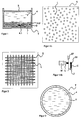
- FIG. 1 shows a schematic longitudinal section through a tank system, with a schematically illustrated failure zone 4.2, the precursor discussed above, over a sediment relief.
- This tank system T for example, is of cylindrical symmetry with an approximately flat bottom 1, it has a wall 2 and a floating roof 3.
- the capacity of such tank systems T can be 100,000 m 3 .
- the floating roof 3 is used for safety reasons to enable the volatile and combustible fractions of the stored crude oil 4 to escape from the tank system T and thus to prevent the formation of explosive mixtures in the tank system T.
- the cover floats directly on the crude oil 4.
- the method according to the invention can also be used for tank systems with a firm roof (firm roof).
- the sediments 4.1 exist, for example from emulsions of water with hydrocarbon fractions, or them consist of segregates of heavy hydrocarbon fractions (hard waxes) or from thickened crude oil or from segregates of mud, sand, salts or from rust and form a solid sediment to viscous oil sludge, also called sludge, which is located on the floor 1 of the tank system T settles.
- the sediments 4.1 exist, for example from emulsions of water with hydrocarbon fractions, or them consist of segregates of heavy hydrocarbon fractions (hard waxes) or from thickened crude oil or from segregates of mud, sand, salts or from rust and form a solid sediment to viscous oil sludge, also called sludge, which is located on the floor 1 of the tank system T settles.
- the thickness of the precipitation zone 4.2 can be in a such tank system T up to 1 m and depends on several difficult to determining parameters, such as the composition of the Crude 4, the ratio of hydrocarbon fractions, for example divided into paraffins, aromatics and naphthenes, and it also depends on The proportion and type of impurities, for example the amount of water or sludge off.
- This compressing precipitation zone 4.2 is, as I said, a kind of precursor Sedimentation from crude oil 4.
- Thickening crude oil is a (thixotropic) mixture, which by mechanical activation from the viscous to the less viscous, liquid physical state can change.
- the condensing Failure zone 4.2 forms as soon as a certain minimum quantity or critical amount of crude oil in a tank system T, seen over time has found a certain metastable balance.
- the critical amount For example, crude oil would be the amount of crude oil needed to form a Allow failure zone 4.2.
- a metastable balance arises, depending according to the type of supply, the supply performance and also the duration the supply of crude oil 4 (whether with interruptions or without) to the tank system T on, this usually happens after a few weeks.
- the crude oil 4 of the tank system T can be influenced by external forces.
- Certain components of crude oil 4, which are in a metastable Precipitation zone 4.2 compress, coagulate and polymerize there and their specific density increases over time in such a way that they are Gravity is drawn to the bottom surface of the dropout zone 4.2 Fail tank system T to form a sediment 4.1.
- the possibilities the coagulation, polymerization and precipitation of crude oil components 4 according to the wide range of variation of a mixture quite diverse and lead them to a stable equilibrium in the form of sediments or sediments 4.1, oil sludge or sludge over. Similar mechanisms of precipitation also apply to other substances that form liquid phases.
- the sedimentation from mixtures such as from crude oil 4, from refinery products and from petrochemical products in Tank systems T avoided by the metastable failure zone 4.2 by external Forces is disturbed, so that coagulation and polymerization of Components of the mixtures is prevented.
- interference devices can thus be in the tank systems T, which act specifically on them.
- Two groups of embodiments of interference devices of the method include hydrodynamic on the one hand and mechanical on the other caused disturbances. The disturbance occurs hydrodynamically through the addition and Removal of crude oil as a disruptive agent in the failure zone 4.2 of the tank system T.
- the Components of the crude oil are thus in motion and the precipitation zone 4.2 is mixed due to the incompressibility of the particles.
- the tank system T is cylindrical and has a circular diameter of up to 100 m and a height of up to 20 m.
- an interference zone of approximately 1 m interference depth is now specified, which according to the concept of the global interference pattern S, that is to say an interference model, is composed of a large number of local interference points L.
- This interference zone is advantageously created at a constant interference height of half a meter with a +/- 50 cm interference effect above the bottom of the tank system T.
- the fault zone extends down to the bottom 1 of the tank system T and can have a volume of several 1000 m 3 (base area x spread of the disturbing effect).
- the failure of the precipitation zone 4.2 is realized according to the invention by hydrodynamic flow or by mechanical vibrations and the latter are advantageously generated by means of strings or bell-shaped membrane in the interior of the tank system T.
- the fault model is therefore first conceived in the process, it connects and optimizes the shape of the tank system T with the shape of the propagation of vibrations in mixtures. With increasing knowledge of the effect, specific fault models can be stored in the computer and modified and output depending on the container, content, shape and environmental influences. According to the optimized fault model, the fault devices are then selected and designed.
- the disturbance pattern S has the shape of a three-dimensional pattern of disturbance points L and forms a two-layer symmetrical arrangement of equidistant "disturbance ellipsoids".
- the two layers cross each other at right angles. They are suitable for long strings to be attached and excited inside the tank system T, similar to two huge, crossed harps, whose antinodes are optimally superimposed in this way. They are designed as long strings that are excited by excitation elements, vibrate in fundamental and partial vibrations and thus deflect the components of the crude oil 4 depending on the size of the amplitude of the sound waves and thus produce an interference or mixing effect.
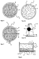
- FIGS. 4a and 4b Another embodiment of a disturbance pattern S according to FIGS. 4a and 4b forms a two-dimensional pattern of disturbance points L, which are designed as more or less equidistant and equally large circular disturbance zones or as arbitrarily distributed disturbance zones.
- T nozzles are attached to the inside of the tank system, or strings to be excited are clamped in or arranged in a bell-shaped membrane.
- the fault points L are in an optimal, corresponding to the fault model Spaced from each other so that they are not too tight and neither stand too far apart and that is in the interference zone between them cannot form trouble-free areas of the failure zone 4.2.
- the Give sizes of the sturgeon ellipsoids in Figure 3 and the interference circles in Figure 4 therefore not the limits of the interference effect of local interference points L, but they only indicate that this fault point L is "active", that is, acting.
- the vibrations to be generated later Will spread medium and thus have a certain range, which is larger than the outer conceptual extent of these impurities L. and which is also greater than the physical extent of those later realized Disruptive means.
- the disruption should occur as homogeneously as possible to fill the volume. she will but locally by means of the interference points L and overall by means of the interference pattern S. or designed globally, always with the aim of training the failure zone 4.2 to prevent such an interference zone. So there are many geometries of interference patterns S, for example three-dimensional structures, have the most tightly packed impurities L. The imperfections must also L itself is not the same size, one can well imagine stronger ones and use weaker defects L combined, in regular or even irregular distances from each other (long and short, thick and thin strings). So difficult geometrical relationships can be overcome in the tank system T, like round walls that so specifically "more" designed to be disturbed.
- the impurities L are not symmetrical, randomly arranged impurities with individual Interference power and interference geometries are used that are sufficient are long-range to form interfering disturbances as overlaps, so that these vibrations of the tank system T as a resonator on the stored crude oil 4 have a volume-filling and homogeneous design. And even symmetrical disturbances can vary widely. So the defects like flat disks far-reaching, but only uniform in one interference level (e.g., sine and circular) or non-uniform (e.g. elliptical) and only here in the the specified interference level. This is advantageous because the one to be prevented Failure zone 4.2 itself is also relatively flat.
- the Those skilled in the art are familiar with the invention in many ways Conception of local fault locations L and global fault patterns S are available.
- the fault pattern S can be designed with standardized fault points L on the drawing board or on the computer as a disturbance model.
- the electronic data processing tool is suitable for this, in which entire libraries of models are built and the field experience save and convert into parameter sets.
- the disturbance pattern S and the defects L are then standardized and proven from a set Embodiments are selected and are selected according to those to be fulfilled Parameters, with the respective geometry of the tank system T or the type of Adjusted crude oil 4. The following shows how this is implemented Figures 5 and 6.
- the interference pattern S according to FIGS. 3 and 4 is superimposed on the base area of the tank system T according to FIG. 2, so that most of the fault locations L located within the fault zone in the tank system T are subsequently realized by means of interference devices .
- the disturbance pattern S is projected onto the geometry of the tank system T, it is not necessary to proceed categorically, but the projection can take place depending on the type and extent of the fault locations L.
- the two layers of interferences L or interfering parabolas shortened in its elongated extent in such a way that it enters the tank system T "fit".
- some are also located within the base of the tank system T located fault locations L or interference circles not realized later. Only such, by comparison with the geometry of the tank system T, which are found to be necessary, are subsequently in Interfering devices V also created.
- the fault zone consists of a volume which consists of the base area of the tank system T and an interference depth is formed and which advantageously includes the failure zone to be disrupted.
- the fault points L are in the following in fault devices advantageously realized as strings or bell-shaped membrane. Each this string or bell-shaped membrane is a realized local fault L with a local disturbance volume.
- FIGS. 7 and 8 schematically show part of an exemplary embodiment of a disturbance device V which works according to the method according to the invention.
- Figure 7 shows a top view
- Figure 8 shows a side view.
- the geometries of the jamming device V with its jamming means 8 and the tank system T are matched to one another in order to achieve an optimal, ie volume-filling and homogeneous malfunction.
- the jamming device has jamming means 8 in the form of strings that can be excited as realized jamming points.
- the interference means 8 are equidistant, strings of different lengths in two constant interference heights 9, 10 above the floor 1 of the tank system T, for example at a height of 40 cm (lower interference height 9) and a height of 60 cm (higher noise level 10) arranged.
- the fault zone covers the entire base area of the tank system T. With an interference effect of + / - 50 cm, it extends down to the bottom 1 of the tank system T and includes the failure zone 4.2 to be disrupted or prevented.
- the tensioned strings of this embodiment of the jammer V. by means of stylized excitation elements 5 via two pull / push units 6 excitable.
- the strings are advantageously in the middle their length stimulated to vibrate.
- Such excitation elements 5 can Thorns or spring-back clubs that are attached to pulling and pushing units 6 are attached.
- the ones that are at rest or slightly vibrating Strings are excited by moving the excitation elements 5 back and forth.
- the excitation elements 5 are brought up to the strings to be excited, these are deflected, tensioned (by plucking), released, the Excitation element 5 moves away from the strings, whereupon the strings undisturbed can swing.
- the strings, their tensioners and the tension and Thrust units 6 for excitation elements 5 are advantageously in several Layers attached so that the swinging of the strings and the fore and aft Return movement of the pull and push units 6 with excitation elements 5 do not hinder each other.
- the strings can be tensioned differently depending on their length and they can be worked in different thicknesses. They are made of stiff materials, For example, wires made of metals such as steel, copper, alloys, possibly plastic and metallized plastics. The prerequisite is that the Materials from crude oil 4 are not attacked and are capable of vibrating. Long strings should not sag so much despite tension and buoyancy, that they have strings arranged underneath or the bottom 1 of the tank system T touch. Large lengths may need to be in two or more strings be divided, which of course also means more devices must be provided to excite the strings. More details about strings, their excitation and tensioning device follow in the description according to Figures 12 and 14, 15th
- the pull and push units 6 have rigid links (rod, piston) or movable links (push / pull chains), for example in slotted tubular guides run smoothly and excitation elements 5 attached to plucking or striking with which they excite the strings.
- the pull and push units 6 run perpendicular to each other and rectilinear in two levels and are outside the tank system T standing, for example crank-operated, fluid-operated or gear-driven drives movable. Details of an advantageous Embodiments of such a drive follow in the description according to Figure 11.
- the pulling and pushing units 6 are for example via with stands or the like connected to the slotted tubular guides Devices firmly mounted on the floor 1 of the tank system T and the rigid or movable links can be through bushings 11 on the Boiler wall 2, in the bottom 1 or on top of the tank system T, through the Guide the floating roof 3 outwards. For security reasons, this should Bushings 11 be worked tight, so that the pull and push units 6 can be operated without liquid components to be processed Mixtures such as crude oil 4 escape from the tank system T.
- the train and Thrust units 6 need to pluck or strike the strings, compared with its length resulting from the size of the tank system T, only Over relatively short distances of 10 cm to a maximum of 1 m forwards and backwards be moved.
- the effort for driving the pull and Thrust units 6 relatively low, they are in the guides without essential Frictional losses lubricated by the crude oil 4 stored.
- the Parts of the pulling and pushing units 6, such as the starting or moving members, the tubular guides and the excitation elements 5 are advantageously made of metal such as steel, bronze etc., possibly plastic and metallized Made of plastic, so that it is not affected by the surrounding media can be attacked, causing this drive of the strings largely is maintenance free.
- the disruptive means are not mechanically stressed. she are planned by pairing materials so that the strings get in use remain during the excitation elements in case of wear exposed and can be easily replaced during revisions. she can be detachably attached to pull and push units 6, for example.
- the strings generate enough high-energy vibrations (estimated 1 to 10 watts of power) and advantageously deep (inaudible) Frequencies.
- Those skilled in the art are familiar with the present invention diverse possibilities of realizing such jamming devices V to disposal.
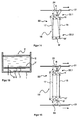
- FIGS. 9B and 10 schematically show part of a second embodiment of an interference device V of the method according to the invention.
- FIG. 9 shows a top view of this
- FIG. 10 shows a side view along the section CC according to FIG. 9.
- the description of this second embodiment coincides in many ways with that of the first embodiment according to FIGS. 7 and 8. In the following, deviations from this are mainly explained .
- equidistant disruptive means 12 attached from one another in the form of bell-shaped membrane or short strings realized in a constant interference height 13 of for example, stand 50 cm above the floor 1 of the tank system T, so that of the entire base area of the tank system T and itself an interference effect of + / - 50 cm around the interference height 13 formed interference zone extends to the bottom 1 of the tank system T and thus the one to be prevented Failure zone 4.2 includes.
- the interference means 12 are by means of excitation elements 5 Excitable via a pull and push unit 6.
- the pull and push unit 6 is made up of movable links like a chain and is therefore spatially flexible.
- the tank system T can consist of chain links that can be rotated relative to one another exist, which are guided in slotted tubular guides will.
- it is spiral in one plane Relocated inside the tank system T. It is firmly on the floor 1 of the tank system T is mounted and is fed through bushings 11 on top of the tank system T, led to the outside in the floating roof 3.
- the excitation elements 5 can small thorns or flails attached to the pull and push units 6 are.
- the ones that are at rest or slightly vibrating bell-shaped membrane or strings are moved forward and backward the excitation elements 5 excited.
- Advantageous embodiments of such bell-shaped membrane or strings follow in the descriptions according to Figures 12 to 15.
- the interference means 12 are the second embodiment So in their outer dimensions smaller than those disruptive means 8 of the first Embodiment.
- the spatially flexible pull and push unit 6 used can roll in large lengths according to a given fault pattern S or model.
- FIG. 9a schematically shows a part of the hydrodynamic embodiment of an interference device V of the method according to the invention, similar to FIG. 9b.
- This jamming device V also consists of pipes 7 which are permanently installed inside the tank system T and which carry the jamming means and which allow the supply and removal of crude oil 4 via jamming means 8 in the form of openings such as perforated pipe networks or nozzles into the tank system T and thus the Formation of a failure zone 4.2 prevented. Details of the hydrodynamic perturbation are discussed below.
- FIGS. 11a and 11b show a schematic top view and side view of part of an embodiment of an exemplary drive for a pulling and pushing unit 6 driving an excitation element 5 in the form of a crank drive.
- This drive can be mounted next to the tank system T or on the floating roof 3 of the tank system T and consists, for example, of a hydraulic motor M with a power of a few kW.
- a slowly rotating crank wheel 27 is driven at approximately 5 or 10 revolutions per minute.
- One end of a connecting rod E is rotatably mounted on a pin Z which is fixedly connected to the flywheel 27 and rotates thereon, the other end of the connecting rod E is rotatably mounted with a piston 28 and this is fixedly connected to the pulling and pushing unit 6 to be driven.
- the crank wheel 27 rotates, the piston 27 is moved linearly back and forth and guided by a guide 29.
- the length of the forward and backward movement of the pulling and pushing unit 6 is equal to twice the circular radius of the pin Z mounted on the flywheel 27 and can therefore be varied relatively easily in the range of 10 cm and 1 m by changing this circular radius.
- the speed of the forward and backward movement of the pulling and pushing unit 6 can be adjusted simply and precisely by varying the speed of rotation of the motor M, for example by varying the reduction ratio U. This is important because the vibration behavior of interference devices V in tank systems T can be regulated and controlled externally. In addition, it is a very slow-running drive unit, which is suitable for continuous operation and requires hardly any maintenance.
- FIGS. 12a, b, c show a schematic view of part of a preferred embodiment of a disturbing means 8, 12 in the form of an oscillatable multiple string 18 with a first embodiment of a tensioning device 16.
- FIGS. 12a, 12b and 12c show how these oscillate Tension multiple strings 18 and their tensioning device 16 after contact with an excitation element 5 and, like this, swing the two strings 15, 17 of the vibratable multiple string 18 after this excitation.
- the vibratable multiple string 18 has two strings 15, 17. You can with their clamping device 16 as a whole according to the disturbance pattern S via supports B, B 'are fixedly mounted on the floor 1 of the tank system T.
- This embodiment has the advantage that the tensioning device 16 with two flexible Brackets H, H 'is worked and that the on the brackets H, H' clamped strings 15, 17 so "mutually" tension.
- the string tension is compensated by the strings 15, 17 and the brackets H, H 'as in the arrow bow.
- the supports B, B 'must have a disturbing means in this embodiment 8.12 withstand a relatively small string tension, this will make the Installation effort for accordingly strong supports and thus saving costs.
- thick steel strings for example 10 mm diameter, which are clamped with great force, must be a clamping device endure considerable tensions, what this "mutual" Bypassing strings.
- the clamping device 16 can also take on other functions, such as the transmission of voltage via flexible brackets H, H '.
- Strings 15.17 the multiple strings 18 can all be excited simultaneously or at different times only certain individual strings can be excited to vibrate.
- the excitation energy is thus in the strings 15.17 and transferred into the brackets H, H ', so that when releasing the contact with the excitation element 5 the system relaxes and begins to oscillate.
- the strings 15, 17 vibrate through mutual excitation with different amplitudes. So it is enough to have a string 15 one To excite multiple strings 18 to vibrate via an excitation element 5, whereby other strings 17 also vibrate and of course vice versa.
- the strings 15, 17 can thus vibrate in natural or partial vibrations are excited and emit sound waves.
- Such a consonant group as shown in Figure 12 produces coupled vibrations, which form a long aftertaste due to phase shifts.
- FIG. 13 shows part of a third embodiment of a disruptive means 12 in the form of an oscillatable bell-shaped membrane.
- a bell-shaped membrane can be excited to one or two natural vibrations and accordingly more partial vibrations. It does not need any tensioning devices and can be fixed in the fault pattern S on the floor 1 of the tank system T using holding means, for example a support. It can be excited via an excitation element 5, which can be firmly connected to the bell-shaped membrane, for example via an elastic connection.
- an excitation element 5 "bobbin-free bell-shaped membrane" movable via the pulling and pushing unit 6 can strike directly by moving back and forth or, according to FIG. 13, a clapper K attached in or on bell-shaped membranes can be deflected via a contact arm A.
- the clapper K can be "prestressed" by the inherent rigidity of the contact arm A to the bell-shaped membrane in a relative equilibrium position, this prestress is stylized by the spring F.
- an excitation element 5 is contacted in a force-transmitting manner with the clapper K via the contact arm A, for example the excitation element 5 and the contacting part of the contact arm A are worked according to FIG. 13 such that during this movement, a concave-shaped area of the excitation element 5 and a convex-shaped area of the contact arm A come into contact.
- the clapper K By moving forward or backward in the same direction of the pulling and pushing unit 6, the clapper K is deflected and the contact arm A is further tensioned.
- the contact arm A When the contact arm A is deflected in a definable manner, the contact between the excitation element 5 and the contact arm A is released, for example it slips a definable deflection over the excitation element 5, the contact arm A relaxes and strikes the clapper K against the wall of the bell-shaped membrane.
- the excitation element 5 is moved back in the opposite direction of the arrow.
- the excitation element 5 and the contacting part of the contact arm A are worked in such a way that there is no force-transmitting contact between the two during this restoring movement of the pulling and pushing unit 6, because two convex regions come into contact with one another and slide past one another laterally.
- FIGS. 14 and 15 are schematic top views of part of a second and third embodiment of tensioning devices for vibratable multiple strings 18. These tensioning devices enable simple assembly of strings 15, 17 that are to be tensioned in the jamming devices according to the invention and they enable the string tensions to be corrected at any time, even after the jamming device has been installed, when the tank system T is filled with crude oil 4. So there are adjustable clamping devices in the clamping force.
- the string tension is set in a single-acting manner via one of the two brackets H, H ', in the embodiment in accordance with FIG. 15 the string tension is adjusted in a double-acting manner via both brackets H, H'.
- a handlebar 24 is rotatably mounted on a holding mandrel B which is in turn firmly anchored in the container; also the bracket H '. To the Handlebar is rotatably attached to the second bracket H. In between are Strings 15 and 17 tensioned. When tightening the clamping unit 21 moves the handlebar and pulls the bracket H with it, the strings tensioned what is shown with the position shown in dashed lines.
- FIG. 14 there is a tensioning element 22 for multiple strings 18 a mobile part 22.1 and a static part 22.2.
- the static part 22.2 is a holder H with clamping points of the ends of the multi-string 18, which over a support B is freely rotatable and firmly mounted on the bottom 1 of the tank system T.
- the mobile Part 22.1 has a similar bracket H 'with clamping points for the Multiple strings 18, for this purpose it is freely rotatably connected to a link 24, which in turn is freely rotatable with a support B 'and rigid with the exciting one Pull and push unit 21 is connected.
- the supports B, B 'by the brackets H, H' largely covered.
- the mobile part has a rotation 22.1 and holding the static part 22.2 of the tensioning element 22 a - Change in position of the multiple strings 18 results in a certain Angle "oblique" to the original position, which according to the embodiment Figure 15 is not the case, here both mobile parts 22.1 rotate and get the position of the multiple strings 18.
- the asymmetrical design of the link 24 causes a leverage, i.e. a long and relatively small force movement of the pull and Thrust units 21 cause a small deflection but greater force on the brackets H, H '.
- Compared to the single-acting clamping device 14 can be used with the double-acting clamping device according to Figure 15 with greater force or it can be with tension a larger number of multiple strings 18 with the same force.
- These two Clamping devices adjustable in the clamping force enable simple and quick assembly or replacement of strings 15.17.
- tensioned strings 15, 17 By relaxing the Tensioning device (backward movement of the exciting pull and push unit 21 against the direction of the drawn arrows) tensioned strings 15, 17 all relaxed, tensioned strings at the same time 15, 17 can then be loose, ie relaxed, with brackets H, H 'of the multiple strings 18 can be connected (for example via quick fasteners, carabiners, etc.) and by tensioning the tensioning device, the jamming device ready for use.
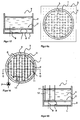
- FIGS. 16, 17 and 18, 19 schematically show parts of a first and second embodiment of a disturbance device V which works according to the method according to the invention.
- FIG. 16 shows a plan view and
- FIG. 17 shows a side view along the sectional plane CC of a first embodiment according to FIG. 16.
- FIG. 18 shows a plan view and
- FIG. 19 shows a side view along the sectional plane DD of another embodiment according to FIG. 18.
- the geometries of the interfering device V with their interfering means 17 and the tank system T are matched to one another in order to achieve an optimal, ie volume-filling and homogeneous disturbance.
- the interfering device has interfering means 8 in the form of nozzles, through which crude oil 4 can flow into and out of the tank system T as the realized interfering points.
- the disruptive means 8 are arranged in a checkerboard geometry and at a constant fault height 9 above the floor 1 of the tank system T, for example in a 50 cm fault height 9.
- the fault zone covers the entire base area of the tank system T. With an interference effect of + / - 50 cm, it extends down to the bottom 1 of the tank system T and includes the failure zone 4.2 to be disrupted or prevented.
- the interference devices V are for those in the process according to FIGS 4 designed fault points L via pipe networks 7 at an adequate fault level 9 Realized and connected to one another above the floor 1 of a tank system T.
- Crude oil 4 for example, is fed into the precipitation zone 4.2 via these pipe networks 7 Via feedthroughs 11 of the pipe networks 7 through the tank system T, or dissipated.
- the supply and discharge takes place via pumps P, which on certain Places the pipe networks are connected.
- the interference means 8 are linear, in a non-branched Pipe network 7 connected to one another, in the embodiment according to FIG. 18 become the disruptive means 8 in a branched pipe network 7 with each other connected.
- Pipe networks 7 can be in the same interference level 9 or in different interference levels 9 stand above the floor 1 of the tank system T, they can be in the same S / N ratio 14 or in different S / N intervals from each other and from the Wall of the tank system T stand.
- the geometry of the interference devices V is advantageously adapted Geometry of the tank system T in order to achieve an optimal, i.e. filling the volume as possible and homogeneous supply and removal of crude oil 4 to the level of education to reach a failure zone 4.2.
- the depth of this interference zone around the interference level 9 is referred to as the interference depth, it covers the base area of the tank system T.
- the fault zone covers the whole Base area of the tank system T. With a typical interference effect of It extends +/- 50 cm to the bottom 1 of the tank system T and includes failure zone 4.2 to be disturbed or prevented.
- the interfering means 8 of the interfering devices V are used to supply or remove Crude oil 4 and openings such as perforated pipe components or nozzles the crude oil 4 can flow in or out.
- the specialist offers himself several known and proven techniques to get crude oil 4 throughout Let the interference zone flow out evenly from all nozzles. In the Stör Love 9 there is an overpressure of depending on the height of the crude oil column in the tank system 10, 20 or even 30 atm.
- the locally excreted quantity of crude oil is caused by the pressure in the Pipe networks 7 and the throughput determined by the nozzles.
- the ratio of the amount of crude oil flowing out of the individual nozzles to the amount of crude oil in the pipe networks 7 so low that in Pipe networks 7 due to the outflow of crude oil 4 from the nozzles is not worth mentioning Pressure drop occurs.
- Similar nozzles equal amounts of crude oil 4 are poured.
- the hydrokinetic disturbance in the formation of the precipitation zone 4.2 can also through a combined removal and supply of crude oil 4 from the fault zone can be prevented via a plurality of pipe networks 7 as interfering devices V.
- crude oil 4 would be fed in via pipe networks 7 (for example via nozzles) and at the same time through other pipe networks 7 (For example, be sucked off through openings in these pipe networks 7).
- the pipe networks 7 of this first and second embodiment can be standardized and common pipe components in the crude oil processing industry such as rigid steel components such as linear extensions, there are elbows, tees, etc. made at certain angles weldable to one another and, for example, at the bottom of the tank system T are permanently fixable.
- Such pipe components can be typically circular Have diameters of 5 to 20 cm at the positions of the to be realized Impurities L they have openings or connecting means for the Assembly of nozzles on.
- Such connecting means can be welded sockets or standard flanges.
- These pipe networks 7 can be, for example, fork-shaped Stand mounted at fault level 9 and on floor 1 of the tank system T be fixed firmly.
- FIG. 9a schematically shows part of a further embodiment of an interference device V of the method according to the invention.
- This jamming device V also consists of at least one pipe system 7 permanently installed inside the tank system T, which enables the supply and removal of crude oil 4 via jamming means 8 in the form of openings such as perforated pipe networks or nozzles into the tank system T and thus the formation of a Failure zone 4.2 prevented.
- this embodiment of a jamming device V coincides largely according to those of the first and second embodiment 16 to 19.
- the pipe system 7 is now made uniform flexible pipe components or armored pressure-resistant hoses spiral laid, for example, from metal such as steel or steel alloys are made.
- Such hoses can have typical circular diameters from 10 to 20 cm and they can be in longer lengths, similar to the cable laying, from a roll according to a specified fault pattern S to be relocated.
- These armored pressure-resistant hoses have the advantage of being flexible Laying.
- Such consisting of one or more coupled hoses, flexible pipe network 7, which in an exemplary Tank system T with a diameter of 100 m again at a fixed disturbance 9 of 50 or 60 cm laid according to a fault pattern S in the form of a spiral is required for the implementation of the individual defects as Interference means 8 and their connection no special manufacture of pipe components like extensions and elbows.
- This relocation causes So that pipe components no longer necessarily have flanges need to be connected, which saves time and material. Only the openings or nozzles have to be attached. This can be done during or after installation by drilling openings Cutting threads and attaching standard fasteners such as Flanges happen so that the nozzles are connected to the pipe network 7 can.
- Another advantage of the flexible pipe network 7 is the simplification of conception and calculation of the fault pattern S and the implementation an effective, highly effective fault zone. Because of the spatial flexibility conditionally of the flexible pipe network 8, can now namely Shape of the disturbance pattern S and the shape of the pipe network 8 matched will. Unlike the first and second embodiments, where the via rigidly routable pipe networks 7 only the defects L of the checkerboard Disturbance pattern S can be realized and connected, now takes place in the third embodiment an interaction between the conception of the fault pattern S and the laying of a pipe network 7 instead.
- the local positions of the Hose can now be easily changed, the local position, type and The size of the nozzles can be varied.
- the hose can now no longer have a perfect spiral, but is local in adapted to small fine structures such as waves etc.
- Such adjustments can happen due to any external circumstances, because otherwise local Faults according to fault pattern S were not optimally developed.
- Such Obstacles that are considered in this fine-tuning can for example, eddies and currents on the walls of the tank system T. It is important that this provides the greatest possible freedom in the design of the Disturbance pattern S itself is created.
- the disturbance pattern S does not need a predefined one Shape more like the chess board in the first and second embodiments according to Figures 16 to 19, but it optimizes the specifications itself.
- these requirements can be freely selected, so it is not necessary to lay the pipe network 7 in the form of a spiral, but this is practical and beneficial.
- the flexible hose can be installed For example, permanently fixed to the bottom 1 of the tank system T, on the calculated ones and optimized positions of the nozzles are openings in the hose attached and the nozzles can through such openings and via connecting means such as cut threads or standardized flanges are so that the nozzles are connected pressure-tight to the pipe network 7.
- the same remarks apply as for the selection of the nozzles of the first and second embodiments.
- the pressure in the pipe network 7 and the The throughput of the nozzles to be attached must be coordinated that the crude oil 4 to be poured with sufficient pressure to all nozzles can be transported and so at the end of the pipe network 7 the last nozzle to develop a full disruptive effect.
- FIG. 20 schematically shows part of a further embodiment of an interference device V of the method according to the invention.
- FIG 20 shows a side view of this in section.
- This jammer V consists of a plurality fixed in the floating roof 3 of the tank system T. installed lances 12, which the supply and removal of crude oil 4 Interference means 8 in the form of openings such as nozzles on the lancets 12 in the Enable tank system T and thus prevent the formation of a failure zone 4.2.
- the feed network with the pumps is not shown here.
- the lances 12 can be standardized and common pipe components in the crude oil processing industry such as for example, rigid steel components such as linear extensions, etc. exist.
- fault points L are now as lances 12 and Interference means 8 realized, which are not on the floor 1 of the tank system T, but are permanently installed in the floating roof 3 of the tank system T.
- These lances 12 can via a common, laid outside the tank system T. Pipe or hose network for the removal and supply of crude oil 4, they are connected but can also all individually with other oil reservoirs for the off and Supply of crude oil 4 will be connected.
- the fault zone covers the whole Base area of the tank system T. With a typical disturbance of + / - 50 cm it reaches down to the bottom 1 of the tank system T and closes it failure zone 4.2 to be disrupted or prevented.
- the Lancets set to "disturbance level" again. That way you have that Possibility of immediately without a conversion, new construction, etc. of a storage container to get the benefits of prevention, if a little more cumbersome, but quite practical for longer storage periods. After emptying the Storage container can then be placed on a preventive device of the embodiments discussed above and the exempted ones Use lancets in other containers.
Landscapes
- Chemical & Material Sciences (AREA)
- Chemical Kinetics & Catalysis (AREA)
- Production Of Liquid Hydrocarbon Mixture For Refining Petroleum (AREA)
- Buildings Adapted To Withstand Abnormal External Influences (AREA)
- Separation Of Suspended Particles By Flocculating Agents (AREA)
- Separation Using Semi-Permeable Membranes (AREA)
- Materials For Photolithography (AREA)
- Physical Or Chemical Processes And Apparatus (AREA)
- Mechanical Treatment Of Semiconductor (AREA)
Applications Claiming Priority (5)
| Application Number | Priority Date | Filing Date | Title |
|---|---|---|---|
| CH2469/93 | 1993-08-17 | ||
| CH2468/93 | 1993-08-17 | ||
| CH246993 | 1993-08-17 | ||
| CH246893 | 1993-08-17 | ||
| PCT/EP1994/002717 WO1995005238A1 (de) | 1993-08-17 | 1994-08-16 | Verfahren zur vermeidung von sedimentationen |
Publications (2)
| Publication Number | Publication Date |
|---|---|
| EP0715542A1 EP0715542A1 (de) | 1996-06-12 |
| EP0715542B1 true EP0715542B1 (de) | 1998-03-04 |
Family
ID=25690528
Family Applications (1)
| Application Number | Title | Priority Date | Filing Date |
|---|---|---|---|
| EP94926197A Expired - Lifetime EP0715542B1 (de) | 1993-08-17 | 1994-08-16 | Verfahren zur vermeidung von sedimentationen |
Country Status (7)
| Country | Link |
|---|---|
| EP (1) | EP0715542B1 (da) |
| AT (1) | ATE163569T1 (da) |
| AU (1) | AU683929B2 (da) |
| DE (1) | DE59405403D1 (da) |
| DK (1) | DK0715542T3 (da) |
| ES (1) | ES2115970T3 (da) |
| WO (1) | WO1995005238A1 (da) |
Families Citing this family (1)
| Publication number | Priority date | Publication date | Assignee | Title |
|---|---|---|---|---|
| CN104926069A (zh) * | 2015-06-24 | 2015-09-23 | 上海市政工程设计研究总院(集团)有限公司 | 用于污泥浓缩池进水口的挡水装置 |
Family Cites Families (7)
| Publication number | Priority date | Publication date | Assignee | Title |
|---|---|---|---|---|
| CH161777A (de) * | 1932-12-21 | 1933-05-31 | Wyss Paul | Verfahren und Einrichtung zum Aufrühren von Jauche in Jauchegruben. |
| CH289372A (de) * | 1948-03-20 | 1953-03-15 | Mueller Hans | Vorrichtung zum Bewegen einer Flüssigkeit mittels eines vibrierenden Organs. |
| US3081239A (en) * | 1961-07-13 | 1963-03-12 | Udylite Corp | Slurry agitator mechanism |
| US3466016A (en) * | 1968-05-10 | 1969-09-09 | Dorr Oliver Inc | Agitating apparatus for flocculating treatment of suspensions |
| JPS5835090B2 (ja) * | 1978-09-12 | 1983-07-30 | 三井造船株式会社 | 石油貯蔵タンクの撹拌装置 |
| DE3434669A1 (de) * | 1984-09-21 | 1986-04-03 | Helmut Grassinger Landtechnik GmbH, 7989 Argenbühl | Verfahren und vorrichtung zum umwaelzen einer fluessigkeit |
| DE3512548A1 (de) * | 1985-04-06 | 1986-10-16 | Heinz Josef Bontenackels | Pulsationsmischer |
-
1994
- 1994-08-16 WO PCT/EP1994/002717 patent/WO1995005238A1/de not_active Ceased
- 1994-08-16 AU AU76134/94A patent/AU683929B2/en not_active Ceased
- 1994-08-16 EP EP94926197A patent/EP0715542B1/de not_active Expired - Lifetime
- 1994-08-16 ES ES94926197T patent/ES2115970T3/es not_active Expired - Lifetime
- 1994-08-16 DK DK94926197T patent/DK0715542T3/da active
- 1994-08-16 DE DE59405403T patent/DE59405403D1/de not_active Expired - Fee Related
- 1994-08-16 AT AT94926197T patent/ATE163569T1/de not_active IP Right Cessation
Also Published As
| Publication number | Publication date |
|---|---|
| ATE163569T1 (de) | 1998-03-15 |
| EP0715542A1 (de) | 1996-06-12 |
| ES2115970T3 (es) | 1998-07-01 |
| DK0715542T3 (da) | 1998-09-28 |
| DE59405403D1 (de) | 1998-04-09 |
| AU7613494A (en) | 1995-03-14 |
| WO1995005238A1 (de) | 1995-02-23 |
| AU683929B2 (en) | 1997-11-27 |
Similar Documents
| Publication | Publication Date | Title |
|---|---|---|
| EP0160805B1 (de) | Verfahren zur Rückgewinnung von Rohöl oder Raffinerieprodukten aus zu schlammigem verdicktem bis kompaktem, sedimentiertem Rohöl oder Raffinerieprodukten, sowie Vorrichtung zur Durchführung des Verfahrens | |
| CH614395A5 (de) | Verfahren und vorrichtung zur behandlung von materialien durch ultraschall-longitudinaldruckschwingungen | |
| EP0442454A1 (de) | Verfahren und Vorrichtung zur Entfernung von Schadstoffen aus Untergrund-Formationen im Erdboden | |
| DE2432937A1 (de) | Sedimentations-vorrichtung | |
| DE3853845T2 (de) | Vortex-Ring-Mischer. | |
| EP1203888A1 (de) | Vorrichtung zur beinflussung der strömung eines strömenden mediums | |
| DE2439991A1 (de) | Verfahren zum eindicken von klaerschlamm und einrichtung zur durchfuehrung des verfahrens | |
| EP0715542B1 (de) | Verfahren zur vermeidung von sedimentationen | |
| DE1931978A1 (de) | Vorrichtung zur Behandlung von Schlammwasser | |
| DE2331242C3 (de) | Vorrichtung zum Homogenisieren eines Schwebefilters | |
| WO2003031340A1 (de) | Vorrichtung und verfahren zur entfernung von öl oder schwimmenden stoffen von einer wasseroberfläche | |
| DE2942303A1 (de) | Verfahren zum abbau von meeressedimenten mittels eines freihaengenden saugrohres sowie anordnung zur durchfuehrung des verfahrens | |
| EP1494975A1 (de) | Vorrichtung zur desintegration von kl rschlamm | |
| DE3429412A1 (de) | Mischvorrichtung | |
| DE4407343C2 (de) | Vorrichtung zum Abscheiden von Partikeln mit fester Konsistenz aus einer Flüssigkeit | |
| DE69913948T2 (de) | Trenngitter | |
| DE2734613A1 (de) | Vorrichtung zum trennen waesseriger suspensionen, insbesondere bei abwaesserschlaemmen | |
| DE4440707B4 (de) | Vorrichtung zum Reinigen von kontaminiertem Erdreich | |
| DE10331022A1 (de) | Verfahren zur Entfernung von magnetisierbaren Metallteilen aus einer Papierfasersuspension | |
| DE4336787C1 (de) | Modul für biologische Abwasserreinigung | |
| DE959990C (de) | Verfahren zur Behandlung mittels Ultraschall von in einem Dispersionsmittel feinverteilten Stoffen | |
| DE4221086A1 (de) | Verfahren und vorrichtung zum beseitigen von material unterhalb des spiegels eines mediums | |
| US5830283A (en) | Method for avoiding sedimentation | |
| DE723903C (de) | Verfahren zur Verdichtung natuerlicher oder kuenstlicher, wassergesaettigter, loser Bodenmassen | |
| DE2837176C2 (de) | Flüssigkeitsmischvorrichtung und mit ihr aufgebaute Anlage zur Behandlung von Schüttgut |
Legal Events
| Date | Code | Title | Description |
|---|---|---|---|
| PUAI | Public reference made under article 153(3) epc to a published international application that has entered the european phase |
Free format text: ORIGINAL CODE: 0009012 |
|
| AK | Designated contracting states |
Kind code of ref document: A1 Designated state(s): AT BE CH DE DK ES FR GB GR IE IT LI LU MC NL PT SE |
|
| AX | Request for extension of the european patent |
Free format text: LT PAYMENT 960322;SI PAYMENT 960322 |
|
| RAX | Requested extension states of the european patent have changed |
Free format text: LT PAYMENT 960311;SI PAYMENT 960311 |
|
| 17P | Request for examination filed |
Effective date: 19960311 |
|
| RAX | Requested extension states of the european patent have changed |
Free format text: LT PAYMENT 960311;SI |
|
| RAX | Requested extension states of the european patent have changed |
Free format text: LT PAYMENT 960311;SI PAYMENT 960311 |
|
| 17Q | First examination report despatched |
Effective date: 19960709 |
|
| GRAG | Despatch of communication of intention to grant |
Free format text: ORIGINAL CODE: EPIDOS AGRA |
|
| GRAH | Despatch of communication of intention to grant a patent |
Free format text: ORIGINAL CODE: EPIDOS IGRA |
|
| GRAH | Despatch of communication of intention to grant a patent |
Free format text: ORIGINAL CODE: EPIDOS IGRA |
|
| RAP1 | Party data changed (applicant data changed or rights of an application transferred) |
Owner name: LINDENPORT SA |
|
| GRAA | (expected) grant |
Free format text: ORIGINAL CODE: 0009210 |
|
| AK | Designated contracting states |
Kind code of ref document: B1 Designated state(s): AT BE CH DE DK ES FR GB GR IE IT LI LU MC NL PT SE |
|
| AX | Request for extension of the european patent |
Free format text: LT PAYMENT 960311;SI PAYMENT 960311 |
|
| LTIE | Lt: invalidation of european patent or patent extension | ||
| PG25 | Lapsed in a contracting state [announced via postgrant information from national office to epo] |
Ref country code: GR Free format text: LAPSE BECAUSE OF FAILURE TO SUBMIT A TRANSLATION OF THE DESCRIPTION OR TO PAY THE FEE WITHIN THE PRESCRIBED TIME-LIMIT Effective date: 19980304 |
|
| REF | Corresponds to: |
Ref document number: 163569 Country of ref document: AT Date of ref document: 19980315 Kind code of ref document: T |
|
| ITF | It: translation for a ep patent filed | ||
| REG | Reference to a national code |
Ref country code: CH Ref legal event code: EP |
|
| ET | Fr: translation filed | ||
| REF | Corresponds to: |
Ref document number: 59405403 Country of ref document: DE Date of ref document: 19980409 |
|
| GBT | Gb: translation of ep patent filed (gb section 77(6)(a)/1977) |
Effective date: 19980501 |
|
| REG | Reference to a national code |
Ref country code: CH Ref legal event code: NV Representative=s name: FREI PATENTANWALTSBUERO |
|
| PG25 | Lapsed in a contracting state [announced via postgrant information from national office to epo] |
Ref country code: SE Free format text: LAPSE BECAUSE OF FAILURE TO SUBMIT A TRANSLATION OF THE DESCRIPTION OR TO PAY THE FEE WITHIN THE PRESCRIBED TIME-LIMIT Effective date: 19980604 Ref country code: PT Free format text: LAPSE BECAUSE OF FAILURE TO SUBMIT A TRANSLATION OF THE DESCRIPTION OR TO PAY THE FEE WITHIN THE PRESCRIBED TIME-LIMIT Effective date: 19980604 |
|
| REG | Reference to a national code |
Ref country code: ES Ref legal event code: FG2A Ref document number: 2115970 Country of ref document: ES Kind code of ref document: T3 |
|
| REG | Reference to a national code |
Ref country code: IE Ref legal event code: FG4D Free format text: 79209 |
|
| REG | Reference to a national code |
Ref country code: DK Ref legal event code: T3 |
|
| PLBE | No opposition filed within time limit |
Free format text: ORIGINAL CODE: 0009261 |
|
| STAA | Information on the status of an ep patent application or granted ep patent |
Free format text: STATUS: NO OPPOSITION FILED WITHIN TIME LIMIT |
|
| 26N | No opposition filed | ||
| PG25 | Lapsed in a contracting state [announced via postgrant information from national office to epo] |
Ref country code: MC Free format text: LAPSE BECAUSE OF NON-PAYMENT OF DUE FEES Effective date: 19990228 |
|
| REG | Reference to a national code |
Ref country code: GB Ref legal event code: IF02 |
|
| PGFP | Annual fee paid to national office [announced via postgrant information from national office to epo] |
Ref country code: NL Payment date: 20060824 Year of fee payment: 13 Ref country code: LU Payment date: 20060824 Year of fee payment: 13 Ref country code: GB Payment date: 20060824 Year of fee payment: 13 Ref country code: FR Payment date: 20060824 Year of fee payment: 13 Ref country code: DK Payment date: 20060824 Year of fee payment: 13 Ref country code: DE Payment date: 20060824 Year of fee payment: 13 |
|
| PGFP | Annual fee paid to national office [announced via postgrant information from national office to epo] |
Ref country code: IE Payment date: 20060825 Year of fee payment: 13 Ref country code: AT Payment date: 20060825 Year of fee payment: 13 |
|
| PGFP | Annual fee paid to national office [announced via postgrant information from national office to epo] |
Ref country code: ES Payment date: 20060830 Year of fee payment: 13 |
|
| PGFP | Annual fee paid to national office [announced via postgrant information from national office to epo] |
Ref country code: IT Payment date: 20060831 Year of fee payment: 13 |
|
| PGFP | Annual fee paid to national office [announced via postgrant information from national office to epo] |
Ref country code: BE Payment date: 20060901 Year of fee payment: 13 |
|
| PGFP | Annual fee paid to national office [announced via postgrant information from national office to epo] |
Ref country code: CH Payment date: 20060921 Year of fee payment: 13 |
|
| BERE | Be: lapsed |
Owner name: S.A. *LINDENPORT Effective date: 20070831 |
|
| REG | Reference to a national code |
Ref country code: CH Ref legal event code: PL |
|
| REG | Reference to a national code |
Ref country code: DK Ref legal event code: EBP |
|
| GBPC | Gb: european patent ceased through non-payment of renewal fee |
Effective date: 20070816 |
|
| PG25 | Lapsed in a contracting state [announced via postgrant information from national office to epo] |
Ref country code: NL Free format text: LAPSE BECAUSE OF NON-PAYMENT OF DUE FEES Effective date: 20080301 Ref country code: LI Free format text: LAPSE BECAUSE OF NON-PAYMENT OF DUE FEES Effective date: 20070831 Ref country code: CH Free format text: LAPSE BECAUSE OF NON-PAYMENT OF DUE FEES Effective date: 20070831 |
|
| NLV4 | Nl: lapsed or anulled due to non-payment of the annual fee |
Effective date: 20080301 |
|
| REG | Reference to a national code |
Ref country code: IE Ref legal event code: MM4A |
|
| PG25 | Lapsed in a contracting state [announced via postgrant information from national office to epo] |
Ref country code: AT Free format text: LAPSE BECAUSE OF NON-PAYMENT OF DUE FEES Effective date: 20070816 |
|
| REG | Reference to a national code |
Ref country code: FR Ref legal event code: ST Effective date: 20080430 |
|
| PG25 | Lapsed in a contracting state [announced via postgrant information from national office to epo] |
Ref country code: DK Free format text: LAPSE BECAUSE OF NON-PAYMENT OF DUE FEES Effective date: 20070831 Ref country code: DE Free format text: LAPSE BECAUSE OF NON-PAYMENT OF DUE FEES Effective date: 20080301 |
|
| PG25 | Lapsed in a contracting state [announced via postgrant information from national office to epo] |
Ref country code: BE Free format text: LAPSE BECAUSE OF NON-PAYMENT OF DUE FEES Effective date: 20070831 |
|
| PG25 | Lapsed in a contracting state [announced via postgrant information from national office to epo] |
Ref country code: IE Free format text: LAPSE BECAUSE OF NON-PAYMENT OF DUE FEES Effective date: 20070816 Ref country code: FR Free format text: LAPSE BECAUSE OF NON-PAYMENT OF DUE FEES Effective date: 20070831 |
|
| REG | Reference to a national code |
Ref country code: ES Ref legal event code: FD2A Effective date: 20070817 |
|
| PG25 | Lapsed in a contracting state [announced via postgrant information from national office to epo] |
Ref country code: GB Free format text: LAPSE BECAUSE OF NON-PAYMENT OF DUE FEES Effective date: 20070816 |
|
| PG25 | Lapsed in a contracting state [announced via postgrant information from national office to epo] |
Ref country code: ES Free format text: LAPSE BECAUSE OF NON-PAYMENT OF DUE FEES Effective date: 20070817 |
|
| PG25 | Lapsed in a contracting state [announced via postgrant information from national office to epo] |
Ref country code: LU Free format text: LAPSE BECAUSE OF NON-PAYMENT OF DUE FEES Effective date: 20070816 |
|
| PG25 | Lapsed in a contracting state [announced via postgrant information from national office to epo] |
Ref country code: IT Free format text: LAPSE BECAUSE OF NON-PAYMENT OF DUE FEES Effective date: 20070816 |