EP0714745A1 - Vorrichtung und Verfahren zum Spritzgiessen eines thermoplastischen Kunstharzformteils - Google Patents
Vorrichtung und Verfahren zum Spritzgiessen eines thermoplastischen Kunstharzformteils Download PDFInfo
- Publication number
- EP0714745A1 EP0714745A1 EP94119061A EP94119061A EP0714745A1 EP 0714745 A1 EP0714745 A1 EP 0714745A1 EP 94119061 A EP94119061 A EP 94119061A EP 94119061 A EP94119061 A EP 94119061A EP 0714745 A1 EP0714745 A1 EP 0714745A1
- Authority
- EP
- European Patent Office
- Prior art keywords
- foaming agent
- plastic material
- liquid foaming
- injection
- forming apparatus
- Prior art date
- Legal status (The legal status is an assumption and is not a legal conclusion. Google has not performed a legal analysis and makes no representation as to the accuracy of the status listed.)
- Granted
Links
- 238000000034 method Methods 0.000 title claims abstract description 29
- 238000001746 injection moulding Methods 0.000 title claims abstract description 10
- 229920005992 thermoplastic resin Polymers 0.000 title description 12
- 239000004088 foaming agent Substances 0.000 claims abstract description 72
- 239000007788 liquid Substances 0.000 claims abstract description 69
- 238000002347 injection Methods 0.000 claims abstract description 65
- 239000007924 injection Substances 0.000 claims abstract description 65
- 239000011800 void material Substances 0.000 claims abstract description 62
- 239000004033 plastic Substances 0.000 claims abstract description 45
- 239000000463 material Substances 0.000 claims abstract description 30
- 238000000465 moulding Methods 0.000 claims abstract description 8
- 150000005827 chlorofluoro hydrocarbons Chemical class 0.000 claims description 3
- LFQSCWFLJHTTHZ-UHFFFAOYSA-N Ethanol Chemical class CCO LFQSCWFLJHTTHZ-UHFFFAOYSA-N 0.000 claims description 2
- OKKJLVBELUTLKV-UHFFFAOYSA-N Methanol Chemical class OC OKKJLVBELUTLKV-UHFFFAOYSA-N 0.000 claims description 2
- 235000019441 ethanol Nutrition 0.000 claims description 2
- CSCPPACGZOOCGX-UHFFFAOYSA-N Acetone Chemical class CC(C)=O CSCPPACGZOOCGX-UHFFFAOYSA-N 0.000 claims 1
- 230000008016 vaporization Effects 0.000 claims 1
- 239000000088 plastic resin Substances 0.000 description 23
- 238000001816 cooling Methods 0.000 description 6
- 229920001169 thermoplastic Polymers 0.000 description 6
- 239000004416 thermosoftening plastic Substances 0.000 description 6
- 229920005989 resin Polymers 0.000 description 5
- 239000011347 resin Substances 0.000 description 5
- 230000007547 defect Effects 0.000 description 4
- 230000001939 inductive effect Effects 0.000 description 4
- 238000007796 conventional method Methods 0.000 description 3
- 238000001704 evaporation Methods 0.000 description 3
- 230000008020 evaporation Effects 0.000 description 3
- 238000005187 foaming Methods 0.000 description 3
- 238000004519 manufacturing process Methods 0.000 description 3
- 238000010521 absorption reaction Methods 0.000 description 2
- 230000015572 biosynthetic process Effects 0.000 description 2
- 230000035515 penetration Effects 0.000 description 2
- CXIGIYYQHHRBJC-UHFFFAOYSA-N 1,1,1,4,4,4-hexafluorobutane Chemical compound FC(F)(F)CCC(F)(F)F CXIGIYYQHHRBJC-UHFFFAOYSA-N 0.000 description 1
- OHMHBGPWCHTMQE-UHFFFAOYSA-N 2,2-dichloro-1,1,1-trifluoroethane Chemical compound FC(F)(F)C(Cl)Cl OHMHBGPWCHTMQE-UHFFFAOYSA-N 0.000 description 1
- 239000004793 Polystyrene Substances 0.000 description 1
- 238000009933 burial Methods 0.000 description 1
- 230000001627 detrimental effect Effects 0.000 description 1
- 230000000694 effects Effects 0.000 description 1
- 238000004880 explosion Methods 0.000 description 1
- 238000005259 measurement Methods 0.000 description 1
- 229920002223 polystyrene Polymers 0.000 description 1
- 229920005990 polystyrene resin Polymers 0.000 description 1
- 238000002360 preparation method Methods 0.000 description 1
- 230000002265 prevention Effects 0.000 description 1
- 238000004904 shortening Methods 0.000 description 1
- 239000012815 thermoplastic material Substances 0.000 description 1
Images



Classifications
-
- B—PERFORMING OPERATIONS; TRANSPORTING
- B29—WORKING OF PLASTICS; WORKING OF SUBSTANCES IN A PLASTIC STATE IN GENERAL
- B29C—SHAPING OR JOINING OF PLASTICS; SHAPING OF MATERIAL IN A PLASTIC STATE, NOT OTHERWISE PROVIDED FOR; AFTER-TREATMENT OF THE SHAPED PRODUCTS, e.g. REPAIRING
- B29C45/00—Injection moulding, i.e. forcing the required volume of moulding material through a nozzle into a closed mould; Apparatus therefor
- B29C45/17—Component parts, details or accessories; Auxiliary operations
- B29C45/1703—Introducing an auxiliary fluid into the mould
- B29C45/1704—Introducing an auxiliary fluid into the mould the fluid being introduced into the interior of the injected material which is still in a molten state, e.g. for producing hollow articles
- B29C45/1706—Introducing an auxiliary fluid into the mould the fluid being introduced into the interior of the injected material which is still in a molten state, e.g. for producing hollow articles using particular fluids or fluid generating substances
-
- B—PERFORMING OPERATIONS; TRANSPORTING
- B29—WORKING OF PLASTICS; WORKING OF SUBSTANCES IN A PLASTIC STATE IN GENERAL
- B29C—SHAPING OR JOINING OF PLASTICS; SHAPING OF MATERIAL IN A PLASTIC STATE, NOT OTHERWISE PROVIDED FOR; AFTER-TREATMENT OF THE SHAPED PRODUCTS, e.g. REPAIRING
- B29C45/00—Injection moulding, i.e. forcing the required volume of moulding material through a nozzle into a closed mould; Apparatus therefor
- B29C45/17—Component parts, details or accessories; Auxiliary operations
- B29C45/1703—Introducing an auxiliary fluid into the mould
- B29C45/1704—Introducing an auxiliary fluid into the mould the fluid being introduced into the interior of the injected material which is still in a molten state, e.g. for producing hollow articles
- B29C45/1706—Introducing an auxiliary fluid into the mould the fluid being introduced into the interior of the injected material which is still in a molten state, e.g. for producing hollow articles using particular fluids or fluid generating substances
- B29C2045/1707—Introducing an auxiliary fluid into the mould the fluid being introduced into the interior of the injected material which is still in a molten state, e.g. for producing hollow articles using particular fluids or fluid generating substances using a liquid, e.g. water
-
- B—PERFORMING OPERATIONS; TRANSPORTING
- B29—WORKING OF PLASTICS; WORKING OF SUBSTANCES IN A PLASTIC STATE IN GENERAL
- B29C—SHAPING OR JOINING OF PLASTICS; SHAPING OF MATERIAL IN A PLASTIC STATE, NOT OTHERWISE PROVIDED FOR; AFTER-TREATMENT OF THE SHAPED PRODUCTS, e.g. REPAIRING
- B29C45/00—Injection moulding, i.e. forcing the required volume of moulding material through a nozzle into a closed mould; Apparatus therefor
- B29C45/17—Component parts, details or accessories; Auxiliary operations
- B29C45/1703—Introducing an auxiliary fluid into the mould
- B29C45/1704—Introducing an auxiliary fluid into the mould the fluid being introduced into the interior of the injected material which is still in a molten state, e.g. for producing hollow articles
- B29C45/1706—Introducing an auxiliary fluid into the mould the fluid being introduced into the interior of the injected material which is still in a molten state, e.g. for producing hollow articles using particular fluids or fluid generating substances
- B29C2045/171—Introducing an auxiliary fluid into the mould the fluid being introduced into the interior of the injected material which is still in a molten state, e.g. for producing hollow articles using particular fluids or fluid generating substances using an evaporating substance
Definitions
- the present invention relates to an apparatus and process for injection molding a thermoplastic resin article, and more particularly, it relates to a process for injection molding a void thermoplastic article wherein a void is formed in a part of the thermoplastic article by injecting a liquid foaming agent through an injection apparatus into the injected thermoplastic material in a mold cavity of a plastic injection mold unit.
- thermoplastic article when a thermoplastic article is injection-molded through an injection mold unit, the article often has a thick wall section which is designed to reinforce its strength. In this case, it takes more time for the thick section to get hardened than a thin section in that the former contains a relatively higher amount of heat than the latter. Consequently, the thick section is likely to have various surface defects, such as sink marks and twists.
- a conventional method for eliminating sink marks caused by the shrinkage of resin is to apply additional pressure to offset the shrinkage of a thermoplastic resin immediately after the injection of the thermoplastic resin has been completed. However, it is hard to expect a maximum effect from that conventional method especially when a molded article has a relatively large difference of thickness between its thick wall portion and thin wall portion and also when an article has a complex structure.
- a foaming method has been developed to be used in order to eliminate sink marks appearing on the surface of the relatively thick wall portion of an article.
- This foaming method is designed to prevent the appearance of sink marks by means of injecting both a thermoplastic resin and a foaming agent at a time so that a hollow portion may be formed within the interior of an article. Nonetheless, this method still faces another problem of surface defects, i.e., swirl marks caused by the foaming gas, which must be solved by a secondary processing.
- U.S. Patent No. 4,101,617 and British Patent Nos. 2,139,548 and 2,202,181 disclose processes of eliminating surface defects, such as sink marks, by means of forming a hollow portion within the interior of an thermoplastic article with the high-pressurized gas of over 150 kg/cm2 injected through a nozzle or a gas-filling device installed in the cavity of an injection mold unit.
- the aforementioned method has a difficulty in forming a preferable hollow inside the article to avoid the appearance of sink marks. Even if a gas can be injected to form a hollow, the pressure of the thermoplastic resin inside a mold cavity drops during injection of the gas so that the thermoplastic resin becomes hardened at the surface of an article. This physical phenomena generates stripe-like marks on the surface of an article. In the worst case, the high-pressurized gas penetrates the surface of an article to make it unacceptable.
- Japanese Patent Application Laid Open No. 5-16177 discloses another method for injection molding to prevent the formation of sink marks, which is characterized by the set-up of a void inducing member in a mold cavity to introduce a pressurized gas to form a void as large as the dimensional reduction of a thermoplastic resin resulting from its shrinking.
- the present invention which is intended to solve various problems deriving from such conventional methods as mentioned above, aims at providing a new molding process and apparatus in which it is possible through a very simple process to prevent surface defects, such as sink marks, twists and stripe-like marks, on a thermoplastic resin article.
- an apparatus for injection molding a void plastic article characterized by that a liquid foaming agent is injected through an injection pin into the injected plastic material in a mold cavity of a plastic injection mold unit.
- the injection pin is assembled with the void forming apparatus which is mounted at a location of a movable mold section or of a stationary mold section.
- the liquid foaming agent is injected through an injection pin into the injected plastic material in a liquid state without preheating the liquid foaming agent.
- the void forming apparatus consists of an injection pin and an injection cylinder.
- the void forming apparatus carries out periodically reciprocal movement into the mold cavity so that the injection pin may enter the cavity when a liquid foaming agent is injected into plastic material, and that the injection pin may return to its original position.
- a feeding meter is installed in front of the void forming apparatus. The feeding meter measures a predetermined amount of a liquid foaming agent and supplies the liquid foaming agent into the injection cylinder.
- the void forming apparatus with an injection pin to inject a liquid foaming agent is mounted at a location of a movable mold section or of a stationary mold section. More than one void forming apparatus may be mounted at locations of a movable mold section or of a stationary mold section in a accordance with the shape of a molded article.
- the liquid foaming agent is injected through the injection pin immediately after the total amount of the molten plastic material for an article is injected by a molding machine or after most of the molten plastic material for an article is injected by a molding machine.
- a liquid foaming agent is injected into the plastic material in a mold cavity, the liquid foaming agent is heated by heat of the plastic material and vaporized so as to form the void portion of a plastic article.
- the gasified foaming agent in the void portion becomes dormant after substantial cooling and hardening of the plastic article.
- the present invention provides a process of injection molding for forming a plastic article as set out in claims 5 to 11.
- a liquid foaming agent is injected either in the course of filling a plastic resin or after the plastic resin has been filled up, and the former process is applied when it is required to make a void large due to the thickness of the thick wall portion of a molded article, while the latter is recommended for the prevention of partial shrinking.
- the injection of a liquid foaming agent is carried out instantaneously so that the plastic resin near the injection pin may not get solidified.
- the failure of an instant injection will result in generating sink marks because the injected foaming agent will evaporate due to the remaining heat of the plastic resin.
- the required time for injection of a liquid foaming agent depends on the thickness of a product, but usually less than five seconds are allowed for the injection while less than two seconds are more preferable.
- the amount of a liquid foaming agent to be injected is determined considering both the volume(A) corresponding to the shrinkage of a product and the volume(B) of the gasified foaming agent. It is more effective to keep the volume(B) a little bit larger than the volume(A).
- the void forming apparatus for injecting a liquid foaming agent is operated by a timer according to the signal emitted from the injection mold machine.
- the preferable diameter of the pin may be 0.2 to 1 mm so that the trace of the pin can be easily buried by the molten plastic resin.
- the mold unit used for the present invention is designed to fit for a plastic molded article with thick wall portions, and therefore the wall of the mold cavity is pierced with a hole at the corresponding position of each thick portion to allow an injection pin to penetrate the molten plastic resin and inject a liquid foaming agent.
- liquid foaming agent used in the present invention it is required for the liquid foaming agent to have the following characteristics;
- liquid foaming agent there is not a liquid foaming agent that may completely satisfy all the above requirements, so it is desired to select the type of a foaming agent which is the most in proximity to such conditions according to the type of resin to be used.
- Preferable liquid foaming agents are methanols, hydrochlorofluorocarbons, chlorofluorohydrocarbon, 1,1,1,4,4,4-hexafluorobutane, ethanols, and acetons.
- a predetermined amount of a liquid foaming agent is injected instantaneously through the void forming apparatus installed at a predetermined position where a void is formed. Influenced by the residual heat of the molten plastic resin, the injected foaming agent gets gasified instantly within the resin, producing an evaporation pressure and forming a void. Then the plastic resin gets cooled and hardened, beginning to shrink. As this shrinkage is offset by the evaporation pressure of the gasified foaming agent, sink marks can be prevented on the surface of the thick wall portion of a molded article.
- the pin for injecting the liquid foaming agent must be slim as mentioned previously. With a slim pin, it is possible to minimize the area of penetration into the plastic resin and it is easy for the penetration hole to be buried by the yet unsolidified resin after the pullout of the pin. With the method used in the present invention, it is easy to control the size and position of a void by means of a void forming apparatus which forms a void through evaporation of a liquid foaming agent by the residual heat of the plastic resin. The absorption of the residual heat of the plastic resin by the liquid foaming agent results in shortening the total cycle time to manufacture an article, thus reducing the production cost.
- a slim pin for injecting a liquid foaming agent provides an excellent configuration on the surface of a molded article thanks to the smooth burial of the injection trace by the plastic resin and also presents a higher degree of freedom for designing an article.
- a void forming apparatus for injecting a liquid foaming agent can be installed either to the movable part or to the stationary part of a mold unit.
- Fig. 1 is a perspective view of a thermoplastic molded article which shows sink marks at a thick part of the molded article.
- the molded article 10 is formed by the injection of a thermoplastic resin through a gate and it consists of two different parts, a thick wall portion 13 and a thin wall portion 12. A conventional injection molding method would likely produce sink marks on the surfaces within the dotted circles 15 and 16.
- Fig. 2 is a sectional view of an injection mold unit to be used in the present invention.
- the mold unit 20 consists of a stationary mold section 21 and a movable mold section 22 so as to form a mold cavity.
- the void forming apparatus consisting of an injection pin 25 and an injection cylinder 24 is installed at the movable section 22 of the mold unit 20.
- the hydraulic pressure system 29 After receiving a signal from the injection mold machine, the hydraulic pressure system 29 makes the void forming apparatus move into the mold cavity.
- the liquid foaming agent is injected through the injection pin 25, then the void forming apparatus returns to its original position. At the same time, the amount of a liquid foaming agent is predetermined by a feeding meter 28 for preparation of the next cycle.
- the feeding meter 28 is installed at the external wall of the movable mold section 22 or to the interior part of the mold unit. Also the feeding meter may be installed at the stationary mold section 21 and to the core part of the slide.
- Fig. 3 is a sectional view of the injection mold unit with a void forming apparatus after a liquid foaming agent has been injected into the plastic resin during injection of the plastic resin. On being injected, the liquid foaming agent 32 evaporates with the absorption of the residual heat of the plastic resin.
- Fig. 4 shows a sectional view of the injection mold unit with a void forming apparatus after the liquid foaming agent has been gasified so as to form a void in the molded article.
- the injected foaming agent continues to expand to offset the volumetric shrinkage of the plastic resin, thus preventing the formation of sink marks.
- the injection cylinder 24 receives the predetermined amount of a liquid foaming agent from the feeding meter 28 for the next injection.
- the resin gets completely solidified, a molded article 10 is extracted.
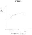
- Fig. 5 is a graph showing the influence of the amount of a liquid foaming agent on the size of a void
- Fig. 6 is a graph showing the influence of the amount of a plastic resin in the mold cavity on the size of a void.
- a mold unit 20 shown in Fig. 2 was used in order to manufacture a molded article as shown in Fig. 1.
- Two sets of a void forming apparatus were installed at the movable mold section 21 of the mold unit 20.
- thermoplastic resin A transparent polystyrene resin was used as thermoplastic resin, and hydrochlorofluorocarbon(HCFC) was used as liquid foaming agent.
- the volumetric measurement of HCFC was made at 0.1 cc for the respective void forming apparatus at the left and the right.
- the liquid foaming agent is injected through the void forming apparatus when 93% by volume of the plastic resin was injected into the mold cavity.
- the injection time of the liquid foaming agent was one second.
- the process applying a supplementary pressure was omitted and a molded article was extracted after an immediate cooling process.
- Example 1 In order to find out the performance of the liquid foaming agent, the liquid foaming agent was replaced by 1 cc of air. Other conditions were same as in Example 1.
- the extracted molded article after the cooling showed a small void inside the article, but it also showed a considerable shrinkage on the surfaces of the article.
- the molten polystyrene was injected into the mold cavity with the amount measured with 100 percent of the capacity, and a supplementary pressure was applied for 4 seconds.
- 0.1 cc of HCFC was injected through each void forming apparatus for 2 seconds after the cooling began. After the completion of cooling, the molded article showed that there was a little bit of shrinkage and that the size of the void was small.
- Example 4 was carried out under the same conditions as in Example 1 except that the amount of HCFC was increased each time by a total of 0.1 cc. The result is shown in Fig. 5.
- Example 5 was carried out by differentiating the amount of injected plastic resin under the same conditions as in Example 1. The result is shown in Fig. 6.
Landscapes
- Engineering & Computer Science (AREA)
- Manufacturing & Machinery (AREA)
- Mechanical Engineering (AREA)
- Injection Moulding Of Plastics Or The Like (AREA)
- Moulds For Moulding Plastics Or The Like (AREA)
Priority Applications (2)
| Application Number | Priority Date | Filing Date | Title |
|---|---|---|---|
| DE1994609118 DE69409118T2 (de) | 1994-12-02 | 1994-12-02 | Vorrichtung und Verfahren zum Spritzgiessen eines thermoplastischen Kunstharzformteils |
| EP19940119061 EP0714745B1 (de) | 1994-12-02 | 1994-12-02 | Vorrichtung und Verfahren zum Spritzgiessen eines thermoplastischen Kunstharzformteils |
Applications Claiming Priority (1)
| Application Number | Priority Date | Filing Date | Title |
|---|---|---|---|
| EP19940119061 EP0714745B1 (de) | 1994-12-02 | 1994-12-02 | Vorrichtung und Verfahren zum Spritzgiessen eines thermoplastischen Kunstharzformteils |
Publications (2)
| Publication Number | Publication Date |
|---|---|
| EP0714745A1 true EP0714745A1 (de) | 1996-06-05 |
| EP0714745B1 EP0714745B1 (de) | 1998-03-18 |
Family
ID=8216500
Family Applications (1)
| Application Number | Title | Priority Date | Filing Date |
|---|---|---|---|
| EP19940119061 Expired - Lifetime EP0714745B1 (de) | 1994-12-02 | 1994-12-02 | Vorrichtung und Verfahren zum Spritzgiessen eines thermoplastischen Kunstharzformteils |
Country Status (2)
| Country | Link |
|---|---|
| EP (1) | EP0714745B1 (de) |
| DE (1) | DE69409118T2 (de) |
Cited By (2)
| Publication number | Priority date | Publication date | Assignee | Title |
|---|---|---|---|---|
| GB2322094A (en) * | 1997-02-14 | 1998-08-19 | Peter Michael Woodworth | Method and apparatus for injection moulding |
| CN101430720B (zh) * | 2007-11-09 | 2011-02-09 | 邱维铭 | 用于模内装饰射出成型的分析方法 |
Families Citing this family (1)
| Publication number | Priority date | Publication date | Assignee | Title |
|---|---|---|---|---|
| DE102006034953A1 (de) * | 2006-03-31 | 2007-10-25 | MöllerTech GmbH | Verfahren zum Herstellen eines Artikels mit einem Hohlraum aus einem Kunststoffmaterial |
Citations (4)
| Publication number | Priority date | Publication date | Assignee | Title |
|---|---|---|---|---|
| GB2139548A (en) * | 1983-05-11 | 1984-11-14 | James Watson Hendry | Injection moulding |
| EP0363948A1 (de) * | 1988-10-13 | 1990-04-18 | Klöckner Ferromatik Desma GmbH | Düse für Spritzgiessmaschinen |
| US5127814A (en) * | 1990-11-26 | 1992-07-07 | Nitrojection Corporation | Apparatus for producing a fluid-assisted injection molded product |
| US5139714A (en) * | 1991-06-03 | 1992-08-18 | Siebolt Hettinga | Process for injection molding a hollow plastic article |
-
1994
- 1994-12-02 EP EP19940119061 patent/EP0714745B1/de not_active Expired - Lifetime
- 1994-12-02 DE DE1994609118 patent/DE69409118T2/de not_active Expired - Fee Related
Patent Citations (4)
| Publication number | Priority date | Publication date | Assignee | Title |
|---|---|---|---|---|
| GB2139548A (en) * | 1983-05-11 | 1984-11-14 | James Watson Hendry | Injection moulding |
| EP0363948A1 (de) * | 1988-10-13 | 1990-04-18 | Klöckner Ferromatik Desma GmbH | Düse für Spritzgiessmaschinen |
| US5127814A (en) * | 1990-11-26 | 1992-07-07 | Nitrojection Corporation | Apparatus for producing a fluid-assisted injection molded product |
| US5139714A (en) * | 1991-06-03 | 1992-08-18 | Siebolt Hettinga | Process for injection molding a hollow plastic article |
Cited By (3)
| Publication number | Priority date | Publication date | Assignee | Title |
|---|---|---|---|---|
| GB2322094A (en) * | 1997-02-14 | 1998-08-19 | Peter Michael Woodworth | Method and apparatus for injection moulding |
| GB2322094B (en) * | 1997-02-14 | 2001-12-05 | Peter Michael Woodworth | Method and apparatus for injection moulding of plastics material |
| CN101430720B (zh) * | 2007-11-09 | 2011-02-09 | 邱维铭 | 用于模内装饰射出成型的分析方法 |
Also Published As
| Publication number | Publication date |
|---|---|
| EP0714745B1 (de) | 1998-03-18 |
| DE69409118D1 (de) | 1998-04-23 |
| DE69409118T2 (de) | 1998-07-16 |
Similar Documents
| Publication | Publication Date | Title |
|---|---|---|
| CA1298046C (en) | Method and manufacturing multiple-layer molded articles of thermoplastic material | |
| EP0424435B1 (de) | Verfahren zum einspritzgiessformen | |
| EP0495614B1 (de) | Verfahren zum Spritzgiessen eines thermoplastischen Kunststoffes und Spritzgiessform | |
| JP3174962B2 (ja) | プラスチック成形において表面性向上のためのガス利用方法 | |
| US5167896A (en) | Method of manufacturing a front cabinet for use with a display | |
| CA2110717C (en) | Process for injection molding a hollow plastic article | |
| WO1993014916A1 (en) | Injection molding of plastic article having hollow rib | |
| KR20040086463A (ko) | 발포사출 성형방법 | |
| EP0714745B1 (de) | Vorrichtung und Verfahren zum Spritzgiessen eines thermoplastischen Kunstharzformteils | |
| US5798063A (en) | Molding process using gas under pressure | |
| JPH01168425A (ja) | 中空成形品の製法 | |
| EP0785855B1 (de) | Giessverfahren | |
| KR960014538B1 (ko) | 열가소성 수지 성형품의 사출성형법 및 사출성형 장치 | |
| US6468465B1 (en) | Plastic injection molding with reduced dimensional variations using gas pressure and secondary plastic injection | |
| JPH06262645A (ja) | 射出成形機及び射出成形方法 | |
| MacMillan | High pressure structural foam | |
| JPH05293844A (ja) | 偏肉構造の成形品の射出成形方法 | |
| JPH0380606B2 (de) | ||
| HK1006210B (en) | Method of injection molding a thermoplastic resin and a mold for injection molding | |
| JPH02286214A (ja) | 中空発泡製品の製造方法 | |
| JPH06320591A (ja) | 肉厚成形品の発泡射出成形方法 | |
| JP2001071346A (ja) | 複数層射出成形方法及び複数層射出成形装置 | |
| JPH04201423A (ja) | 中空型物の製造法 | |
| JP3249769B2 (ja) | 射出成形機のノズル | |
| JPH0430329B2 (de) |
Legal Events
| Date | Code | Title | Description |
|---|---|---|---|
| PUAI | Public reference made under article 153(3) epc to a published international application that has entered the european phase |
Free format text: ORIGINAL CODE: 0009012 |
|
| AK | Designated contracting states |
Kind code of ref document: A1 Designated state(s): DE FR GB |
|
| 17P | Request for examination filed |
Effective date: 19960822 |
|
| 17Q | First examination report despatched |
Effective date: 19961011 |
|
| GRAG | Despatch of communication of intention to grant |
Free format text: ORIGINAL CODE: EPIDOS AGRA |
|
| GRAG | Despatch of communication of intention to grant |
Free format text: ORIGINAL CODE: EPIDOS AGRA |
|
| GRAH | Despatch of communication of intention to grant a patent |
Free format text: ORIGINAL CODE: EPIDOS IGRA |
|
| GRAH | Despatch of communication of intention to grant a patent |
Free format text: ORIGINAL CODE: EPIDOS IGRA |
|
| GRAA | (expected) grant |
Free format text: ORIGINAL CODE: 0009210 |
|
| AK | Designated contracting states |
Kind code of ref document: B1 Designated state(s): DE FR GB |
|
| REF | Corresponds to: |
Ref document number: 69409118 Country of ref document: DE Date of ref document: 19980423 |
|
| ET | Fr: translation filed | ||
| ET1 | Fr: translation filed ** revision of the translation of the patent or the claims | ||
| PLBE | No opposition filed within time limit |
Free format text: ORIGINAL CODE: 0009261 |
|
| STAA | Information on the status of an ep patent application or granted ep patent |
Free format text: STATUS: NO OPPOSITION FILED WITHIN TIME LIMIT |
|
| 26N | No opposition filed | ||
| REG | Reference to a national code |
Ref country code: GB Ref legal event code: IF02 |
|
| PGFP | Annual fee paid to national office [announced via postgrant information from national office to epo] |
Ref country code: FR Payment date: 20081212 Year of fee payment: 15 |
|
| PGFP | Annual fee paid to national office [announced via postgrant information from national office to epo] |
Ref country code: DE Payment date: 20081127 Year of fee payment: 15 |
|
| PGFP | Annual fee paid to national office [announced via postgrant information from national office to epo] |
Ref country code: GB Payment date: 20081126 Year of fee payment: 15 |
|
| GBPC | Gb: european patent ceased through non-payment of renewal fee |
Effective date: 20091202 |
|
| REG | Reference to a national code |
Ref country code: FR Ref legal event code: ST Effective date: 20100831 |
|
| PG25 | Lapsed in a contracting state [announced via postgrant information from national office to epo] |
Ref country code: FR Free format text: LAPSE BECAUSE OF NON-PAYMENT OF DUE FEES Effective date: 20091231 |
|
| PG25 | Lapsed in a contracting state [announced via postgrant information from national office to epo] |
Ref country code: DE Free format text: LAPSE BECAUSE OF NON-PAYMENT OF DUE FEES Effective date: 20100701 |
|
| PG25 | Lapsed in a contracting state [announced via postgrant information from national office to epo] |
Ref country code: GB Free format text: LAPSE BECAUSE OF NON-PAYMENT OF DUE FEES Effective date: 20091202 |