EP0713296B1 - Zusammenpassende Spektral-Nullkodes für unvollständige Antwortkanäle - Google Patents
Zusammenpassende Spektral-Nullkodes für unvollständige Antwortkanäle Download PDFInfo
- Publication number
- EP0713296B1 EP0713296B1 EP95308236A EP95308236A EP0713296B1 EP 0713296 B1 EP0713296 B1 EP 0713296B1 EP 95308236 A EP95308236 A EP 95308236A EP 95308236 A EP95308236 A EP 95308236A EP 0713296 B1 EP0713296 B1 EP 0713296B1
- Authority
- EP
- European Patent Office
- Prior art keywords
- code
- data
- word
- code word
- unique
- Prior art date
- Legal status (The legal status is an assumption and is not a legal conclusion. Google has not performed a legal analysis and makes no representation as to the accuracy of the status listed.)
- Expired - Lifetime
Links
Images
Classifications
-
- G—PHYSICS
- G06—COMPUTING OR CALCULATING; COUNTING
- G06F—ELECTRIC DIGITAL DATA PROCESSING
- G06F11/00—Error detection; Error correction; Monitoring
- G06F11/07—Responding to the occurrence of a fault, e.g. fault tolerance
- G06F11/08—Error detection or correction by redundancy in data representation, e.g. by using checking codes
- G06F11/10—Adding special bits or symbols to the coded information, e.g. parity check, casting out 9's or 11's
-
- H—ELECTRICITY
- H03—ELECTRONIC CIRCUITRY
- H03M—CODING; DECODING; CODE CONVERSION IN GENERAL
- H03M13/00—Coding, decoding or code conversion, for error detection or error correction; Coding theory basic assumptions; Coding bounds; Error probability evaluation methods; Channel models; Simulation or testing of codes
-
- H—ELECTRICITY
- H04—ELECTRIC COMMUNICATION TECHNIQUE
- H04L—TRANSMISSION OF DIGITAL INFORMATION, e.g. TELEGRAPHIC COMMUNICATION
- H04L25/00—Baseband systems
- H04L25/38—Synchronous or start-stop systems, e.g. for Baudot code
- H04L25/40—Transmitting circuits; Receiving circuits
- H04L25/49—Transmitting circuits; Receiving circuits using code conversion at the transmitter; using predistortion; using insertion of idle bits for obtaining a desired frequency spectrum; using three or more amplitude levels ; Baseband coding techniques specific to data transmission systems
- H04L25/497—Transmitting circuits; Receiving circuits using code conversion at the transmitter; using predistortion; using insertion of idle bits for obtaining a desired frequency spectrum; using three or more amplitude levels ; Baseband coding techniques specific to data transmission systems by correlative coding, e.g. partial response coding or echo modulation coding transmitters and receivers for partial response systems
-
- G—PHYSICS
- G11—INFORMATION STORAGE
- G11B—INFORMATION STORAGE BASED ON RELATIVE MOVEMENT BETWEEN RECORD CARRIER AND TRANSDUCER
- G11B20/00—Signal processing not specific to the method of recording or reproducing; Circuits therefor
- G11B20/10—Digital recording or reproducing
- G11B20/10009—Improvement or modification of read or write signals
Definitions
- This invention relates generally to encoding and decoding of binary data over partial response channels using maximum likelihood sequence detection (PRML). More particularly, this invention relates to a method for developing a non-quasicatastrophic and phase invariant matched spectral null trellis code having a preselected code rate, wherein the order of the higher order null in the transfer function of the partial response channel is ⁇ 1.
- PRML maximum likelihood sequence detection
- Matched spectral null trellis codes including background theory related thereto are described in more detail in Karabed and Siegel, Matched Spectral-Null Codes For Partial Response Channels, IEEE transactions on Information Theory, Vol 37, No. 3, p. 818 (May 1991). See also U.S. Patents 4,888,775; 4,888,779 and 5,096,484.
- EP 0333324A discloses matched spectral null trellis codes for partial response channels for providing an output having a reliability determined by a preselectable encoding gain.
- a method for coding an input string of data for a partial response channel having a transfer function of the form (1-D)(1+D) n to provide an output having a preselected code rate said method characterised by comprising:
- a method of coding an input string of data for a partial response channel having a transfer function of the form (1-D)(1+D) n to provide an output having a preselected code rate said method characterised by comprising:
- a system for encoding and decoding an input string of data for a partial response channel having a transfer function of the form (1-D)(1+D) n to provide an output having a preselected code rate said system characterised by comprising:
- This system may be advantageously employed for encoding binary data for recordation on storage media such as a computer disc, and for subsequent decoding of retrieved data.
- the encoding method may include selection of a data word length for subdividing a stream of binary data into a succession of data words of uniform length, and selecting a code word length to which each data word is to be translated. For example, in a preferred form of the invention, a stream or string of binary data is subdivided into data words having eight bits, and these data words are translated to code words having ten bits.
- a high code rate, i.e. Rate (R) 8/10, is preferred for optimum use of channel band width.
- An encoding table is developed for translating each data word to a unique code word, using a canonical state diagram (G) for binary sequences having spectral nulls at the Nyquist frequency.
- G canonical state diagram
- the code words can be re-converted to re-create the original data by use of a finite memory Viterbi sequence detection device and method, with each specific code word and its complement translating back to the same data word.
- the present embodiment pertains to an improved method of encoding and decoding binary data, and to the resultant matched spectral null code developed therefrom.
- SNR signal-to-noise
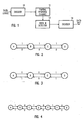
- FIGURE 1 generally illustrates the encoding of a string of binary data at a preselected code rate for recordation of the data as a succession of code words of the fixed length.
- the encoder 10 translates each successive string of data bits of preselected length into a unique code word consisting of a greater number of bits for recordation on the appropriate storage media, as represented by the partial response channel 12.
- Matched spectral null trellis codes and related background theory are described in the literature, e.g., Karabed and Siegel, Matched Spectral-Null Codes For Partial-Response Channels , IEEE Transactions on Information Theory, Vol. 37, No. 3, p. 818 (May 1991), which is incorporated by reference herein. See also U.S. patents 4,888,775; 4,888,779; and 5,095,484.
- the trellis codes discussed in these references have not been adapted to match the higher order null, referred to as the Nyquist null, and thus have not been applicable to the higher order partial response systems.
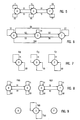
- Binary sequences with spectral null constraints are normally characterized by so-called canonical state diagrams or graphs, as represented by way of example in FIGS. 2 and 3.
- These canonical diagrams can be used as the basis to develop a code for translating arbitrary binary sequences or data words into new binary sequences or code words that can later be converted into a modulated sequence with a spectral null at Nyquist frequency.
- the graph capacity (C) is approximately 0.6942.
- the capacity of either graph can be increased by increasing the number of states (N) while preserving the labelling scheme.
- the graph capacity (C) is the upper limit to the achievable code rate (R) of a code which can be designed from that graph.
- R achievable code rate
- the starting graph must be a canonical state diagram having a Nyquist null labelling scheme, with a number of states (N) where the graph capacity (per Eq. 7) is at least 0.8.
- a 6-state Nyquist null graph has a graph capacity (per Eq. 7) of approximately 0.8495.
- a 7-state Nyquist null graph has a graph capacity of about 0.8857.
- the 7-state graph of FIG. 4 is chosen in the preferred embodiment and is described as follows, since it affords greater convenience and flexibility in designing a code which is both phase invariant and non-quasicatastrophic.
- the n th power of the graph is a graph whose states are the same as the original graph, but in which the label on an edge or path between any pair of states is the sequence of n symbols read off the edges of the path joining those states in the original graph.
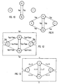
- the 7-state graph of FIG. 4 yields a 3-state subgraph (G) as depicted in FIG. 5, wherein the subgraph (G) represents the second power of the original 7-state graph (FIG. 4).
- a loop in the graph is a path that begins and ends at the same state.
- a loop that does not pass through any other state is referred to as a self-loop.
- the graph is irreducible if there is a path of some length between every pair of states in the graph.
- An irreducible graph is said to be periodic with a period (p) if the length of every loop in the graph is a multiple of (p), with p>1.
- the pth power of a periodic graph with period (p) can be subdivided into (p) disconnected aperiodic graphs.
- the period of the 7-state Nyquist null graph of FIG. 4 equals 2, as can be verified by taking its second power (FIG. 5).
- the second power splits into two graphs, one consisting of states B, D and F (FIG. 5) and the other consisting of states A, C, E and G.
- FIG. 5 shows the 3-state subgraph of the second power, including states B, D and F.
- a loop is referred to as quasicatastrophic if its label is the same in binary code as the label on any other loop.
- the self-loops "11" around states B, D and F are identical, whereby these loops are quasicatastrophic.
- the self-loops "00" for these states are also identical and are thus quasicatastrophic.
- the loops B-D-B and D-F-D are quasicatastrophic since their labels are the same, namely, "0110". If any loop is quasicatastrophic, the graph is referred to as a quasicatastrophic graph. Conversely, if no loop is quasicatastrophic, then the graph is referred to as non-quasicatastrophic.
- a (i, j) 0 if there is no edge between the states (i) and (j)
- a (i, j) r if there are (r) edges between states (i) and (j).
- the adjacency matrix is represented as follows:
- a n is the adjacency matrix for the n th power of the graph.
- a canonical graph is deterministic if, for every state in the graph, the edges leaving that state have distinct labels.
- the n th power of the deterministic graph is also deterministic.
- the subgraph G (FIG. 5) is deterministic.
- AWGN additive white Gaussian noise
- SNR signal-to-noise ratio
- the partial response channels are commonly referred to as the dicode channel, the PR4 channel, the EPR4 channel, and the E 2 PR4 channel, respectively.
- the 7-state state graph of FIG. 4 is then converted to the second power diagram (G) of FIG. 5.
- This second power, 3-state subgraph (G) forms the foundation for the code design procedure.
- the adjacency matrix for the resultant subgraph (G 5 ) is:
- the code word selection process proceeds by arbitrarily removing, i.e., not selecting those code words that would be incompatible with desired non-quasicatastrophic and phase invariant characteristics.
- a code is phase invariant if and only if:
- a code is non-quasicatastrophic if and only if
- FIG. 6 is a reproduction of the subgraph (G 5 ) of FIG. 5, with edge labels rewritten to indicate the set of edges joining each pair of states.
- S1 denotes the set of 132 10-bit labelled edges that begin and end at state B.
- the number of 10-bit labelled edges comprising the sets referred to by S1, S2... S10 are given by the adjacency matrix A 5 (Eq. 9).
- the subgraph (G 5 ) as well as the final code graph to be developed can be viewed as being compiled in increments from the subgraph of (G) that progressively increase in complexity.
- the adjacency matrix A 5 (Eq. 9) can also be viewed as being incrementally generated.
- FIG. 7 illustrates the subgraph (G) in partial form as three 1-state subgraphs G B , G D , and G F .
- Each of these three 1-state subgraphs has 32 different self-loops on each state in (G 5 ).
- These 1-state subgraphs do not generate any other paths in (G 5 ).
- M 1 denote the contribution to the adjacency matrix A 5 by these 1-state graphs:
- the adjacency matrix N for each subgraph will also be identical.
- the adjacency matrix of G BD is:
- the adjacency matrix N 5 also indicates that there are 122 self-loops formed around D in (G 5 ) by G BD .
- 32 of those self-loops are already defined by D alone, such that the interconnection between B and D resulted in 90 additional self-loops around D.
- those 90 additional self-loops around D are the complements of the set referenced above by S DD , and hence are noted in FIG. 9 by S DD .
- G BD and G DG are identical, these 90 additional self-loops are also generated around F in (G 5 ) by G DF , and are thus quasicatastrophic if both sets are included in the final code.
- FIG. 9 indicates selection of the set S DD around state D, but not the corresponding set around state F.
- FIG. 9 thus represents a partial graph of the final code, to include S DD and its complement set S DD .
- FIG. 10 illustrates modification of the partial graph of FIG. 9, by splitting state D into two states D 1 , and D 2 .
- splitting state D new loops D 1 -D 2 -D 1 and D 2 -D 1 -D 2 result, wherein these loops are non-quasicatastrophic in FIG. 10 and in (G).
- G BD From the adjacency matrix N 5 (Eq. 12), it is noted that G BD generates 121 paths from state B to state D in (G 5 ). By symmetry, G DF also generates 121 loops in (G 5 ), with the same labels as the paths between states B and D. Similarly, G BD generates another set of 121 labels for paths from state D to state B, wherein the set in this direction are complements to the set from state B to D.
- the set of loops from B to D are referred to as S BD
- the complement set from D to B is referred to a S BD .
- S DF sets of loops from state D to state F
- S DF complement set of loops from state F to D
- S DF complement set of loops from state F to D
- Both B-D-B and B-D-D-B loops are quasicatastrophic in (G) and thus the code graph should avoid them.
- the edges in S BD should extend from B to D 2
- the edges in S BD should extend from D 1 to B.
- the edges in S BD should extend from D 2 to F
- the edges in S BD should extend from F to D 1 .
- the code graph reflecting these edges, inclusive of the edges selected per FIG. 9, is shown in FIG. 11.
- All of the loops in (G 5 ) that are produced by (G) will be non-quasicatastrophic in (G 5 ). Hence, these loops can be included in the final code, up to a number providing 256 edges leaving each state in the code graph.
- the twenty additional self-loops around state D in (G 5 ) formed by (G) can be evenly distributed between D 1 and D 2 , with ten edges leaving D 1 and the other ten edges leaving D 2 . These two sets of ten edges are complements to each other, and are denoted in FIG. 12 by S DDG and S DDG .
- the set of 43 edges generated by (G) that extend from state B to state D in (G 5 ) is referred to in FIG. 12 by S BDG .
- the set of 43 edges generated by (G) and extend from state D to state F in (G 5 ) are designated S DFG .
- the complement set of 43 edges generated by (G) to extend from state F to state D in (G 5 ) are labelled S BDG
- the complement set of 43 edges generated by (G) to extend from state D to state B in (G 5 ) are labelled S DFG .
- the graph (G) also generates 10 self-loops on state B, denoted in FIG. 12 by S BB , and 10 complement self-loops around state F, labelled S BB in FIG. 12.
- the graph (G) generates 100 edges extending from state B to state F in (G 5 ), identified in FIG. 12 by S BF .
- Another 100 edges are generated to extend from state F to state B in (G 5 ), wherein this set is a complement to S BF , and is thus noted in FIG. 12 as S BF .
- the code graph is shown in FIG. 12, which constitutes a composite of FIGS. 10-11.
- the edges S BDG are shown to extend from state B to D 2
- the edges S DFG are shown to extend from state D 1 to B.
- the symbol "U" on the code graph (FIG. 12) denotes the union of sets.
- the notation S BD U S BDG on the edge connecting state B and D 2 refers to all of the edges in the union of sets S BD and S BDG that extend from state B to D 2 .
- the complexity of the code graph can be reduced by omitting self-loops on states D and F.
- 8 additional edges can be eliminated, for example, from S BD and the complements thereof in S BD . This permits all of the edges in the sets S BDG and S DFG to be utilized, a choice that aids in reducing the detection memory required to implement the code.
- a code word defined by a particular 10-bit pattern or sequence is the label for an edge in the set S BDG , then the path in the code graph is identified as between the states D 2 and F.
- the 10-bit pattern is the label for an edge in the set S BD , it is not possible to specify whether that pattern represents a code graph path between the states B and D 2 or between the states D 2 and F, unless the preceding code word is known. That is, if the preceding code word is the label for an edge in the set S DF or S BD or S DFG , then the current code word represents an edge between states B and D 2 .
- the prior code word is from the sets S BD , S DD or S BDG .
- the current code word represents an edge between the states D 2 and F. Omission of the 8 edges from S BD and S BD avoids the need to know the prior code word in the stream, to thus simplify detection memory.
- the set of all 256 possible 8-bit data words are assigned to individual 10-bit code words, following the rule that any given 10-bit code word and its complement must decode to the same 8-bit data word.
- the resultant code is thus made phase invariant.
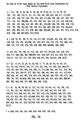
- the final code graph is shown in FIG. 13, wherein the states B, D 1 , D 2 , and F have been re-labelled as 1, 2, 3 and 4, and wherein the sets of edge labels representing 10-bit code words S BD , S BDG , S DFG , S BF , S DD and S DDG have been re-labelled as A, B, C, D, E and F. Similarly, the complement sets have been re-labelled A , B , C , D , E , and F.
- the code represented by FIG. 13 is block decodable.
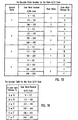
- FIG. 14 is a table wherein the sets of 10-bit code words are listed by decimal equivalent in association with the six re-labelled sets A through F (FIG. 13).
- FIG. 15 is an encoder table representing the operation of a standard 4-state block encoder 10 in FIG. 1 to assign a unique 10-bit code word to each unique 8-bit string of binary data.
- FIG. 16 is a decoder table representing the operation of a decoder for decoding the code words and their complements to retrieve the original data in the form of successive 8-bit strings.
- the SNR gain achieved by use of the matched spectral-null code can be used to improve performance.
- the detector must only use a finite memory, wherein the trellis of such detector is referred to as a finite-memory trellis.
- Another practical constraint is that the complexity of the trellis should not be too great in terms of the total number of states and edges.
- a specific rate 8/10 code has been described in detail, it will be understood that the same methodology can be used to develop other matched spectral null codes at other code rates, such as 3/4, 6/8, etc. Accordingly, it will be understood that the invention is not limited to the embodiment shown and described herein, except as set forth in the appended claims.
Landscapes
- Engineering & Computer Science (AREA)
- Physics & Mathematics (AREA)
- Theoretical Computer Science (AREA)
- Probability & Statistics with Applications (AREA)
- Computer Networks & Wireless Communication (AREA)
- General Engineering & Computer Science (AREA)
- General Physics & Mathematics (AREA)
- Spectroscopy & Molecular Physics (AREA)
- Quality & Reliability (AREA)
- Signal Processing (AREA)
- Error Detection And Correction (AREA)
- Signal Processing For Digital Recording And Reproducing (AREA)
- Compression, Expansion, Code Conversion, And Decoders (AREA)
- Filters That Use Time-Delay Elements (AREA)
- Dc Digital Transmission (AREA)
- Cable Transmission Systems, Equalization Of Radio And Reduction Of Echo (AREA)
Claims (8)
- Verfahren zum Codieren eines Eingabedatenstrings eines Kanals mit Teilantwort mit einer Übertragungsfunktion in der Form (1-D) (1+D)n, um eine Ausgabe bereitzustellen, die eine vorgewählte Coderate hat, wobei das Verfahren gekennzeichnet ist durch:Bestimmen der Häufigkeit, mit der es eine Null höherer Ordnung in der Übertragungsfunktion des Teilantwortkanals gibt, wobei n ≥ 1 ist; undCodieren eines Eingabedatenstrings in einen binären Codestring mit einem Spektraldichtewert gleich Null für diese Häufigkeit; wobeider Codierschritt das Codieren jedes einzigartigen Datenworts in ein entsprechend einziges Codewort entsprechend einer phaseninvarianten und nicht quasi-katastrophenartigen Codiertabelle enthält.
- Verfahren nach Anspruch 1, bei dem der Codierschritt ein Unterteilen des Eingabedatenstrings in einer Folge von Datenwörtern ausgewählter einheitlicher Länge und Übersetzen der Datenwörter jeweils in Codewörter ausgewählter einheitlicher Länge umfaßt, wobei jedes einzigartige Datenwort in ein einzigartiges Codewort übersetzt wird.
- Verfahren nach Anspruch 2, das des weiteren den Schritt des Decodieren der Codewörter zum Neu-Erzeugen des Eingabedatenstrings umfaßt, wobei der Decodierschritt ein Übersetzen jedes einzigartigen Codeworts und dessen Komplements in ein einzigartiges Datenwort, das,zu diesen gehört, umfaßt.
- Verfahren nach Anspruch 2 oder 3, bei dem der Codierschritt das Erzeugen einer Codiertabelle aus einem kanonischen Zustandsdiagramm (G) und (GP) für binäre Folgen mit Spektralnull bei Nyquist-Frequenz umfaßt, wobei die Potenz (P) des Diagramms (GP) eine Funktion der Codewortlänge ist, und wobei des weiteren ein ausgewähltes Codewort, das eine Schleife in dem Diagramm (G) und (GP) bildet, einer Schleife entspricht, die nicht quasi-katastrophenartig in dem Diagramm (G) ist.
- Verfahren zum Codieren eines Eingabedatenstrings eines Zeitantwortkanals mit einer Übertragungsfunktion der Form (1-D) (1+D)n, um eine Ausgabe bereitzustellen, die eine vorgewählte Coderate hat, wobei das Verfahren gekennzeichnet ist durch:Unterteilen eines Eingabedatenstrings in eine Folge von Datenworten ausgewählter einheitlicher Länge, wobei die Anzahl der einzigartigen Datenworte eine Funktion der ausgewählten Datenwortlänge ist;Übersetzen der Datenworte in Codeworte einer ausgewählten einheitlichen Länge, die größer als die ausgewählte Datenwortlänge ist, wobei eine Codiertabelle aus kanonischen Zustandsdiagrammen (G) und (GP) für binäre Folgen erzeugt wird, die spektrale Nullen bei der Nyquist-Frequenz haben, wobei die Potenz (P) des Diagramms (GP) eine Funktion der Codewortlänge ist, wobei für jedes ausgewählte Codewort dessen Komplement ebenfalls ausgewählt wird, wobei ein ausgewähltes Codewort, das eine Schleife in den Diagrammen (G) und (GP) bildet, einer Schleife entspricht, die nicht quasi-katastrophenartig in dem Diagramm (G) ist, und wobei jedes ausgewählte Codewort und sein Komplement zu dem gleichen einzigartigen Datenwort decodiert werden.
- Verfahren nach Anspruch 5, bei dem das kanonische Zustandsdiagramm (G) eine Anzahl von Zuständen hat, die ausreichen, um eine Graph-Kapazität (C) zu ergeben, die das Verhältnis der ausgewählten Datenwortlänge zu der ausgewählten Codewortlänge überschreiten, wobei die Graphen-Kapazität (C) durch die Formel gegeben ist:

- Verfahren nach Anspruch 5 oder 6, das des weiteren den Schritt des Decodieren jedes einzigartigen Codeworts und seines Komplements zu dem selben einzigartigen Datenwort zum Neu-Erzeugen des Eingabedatenstrings enthält.
- System zum Codieren und Decodieren eines Eingabedatenstrings für einen Kanal mit Teilantwort mit einer Übertragungsfunktion in der Form (1-D)(1+D)n, um eine Ausgabe bereitzustellen, die eine im voraus gewählte Coderate hat,
wobei das System gekennzeichnet ist durch:wobei die Codiertabelle aus kanonischen Zustandsdiagrammen (G) und (GP) für binäre Folgen mit spektralen Nullen bei Nyquist-Frequenz erzeugt wird, wobei die Potenz (P) des Diagramms (GP) eine Funktion der Codewortlänge ist, und wobei des weiteren ein ausgewähltes Codewort, das eine Schleife in dem Diagramm (G) und (GP) bildet, einer Schleife entspricht, die nicht quasi-katastrophenartig in dem Diagramm (G) ist; undein finites Speichermittel zum Speichern einer Codiertabelle zum Übersetzen einer Folge von Eingabedatenworten einer ausgewählten einheitlichen Länge in eine Folge von Ausgabecodeworten einer ausgewählten einheitlichen Länge, die größer als die ausgewählte Datenwortlänge ist, wobei jedes einzigartige Datenwort in ein einzigartiges Codewort übersetzt wird;
die Decodiermittel zum Decodieren jedes einzigartigen Codeworts und dessen Komplements zu einem einzigartigen Datenwort, das zu diesen gehört.
Applications Claiming Priority (2)
| Application Number | Priority Date | Filing Date | Title |
|---|---|---|---|
| US342229 | 1994-11-18 | ||
| US08/342,229 US5646950A (en) | 1994-11-18 | 1994-11-18 | Matched spectral null codes for partial response channels |
Publications (3)
| Publication Number | Publication Date |
|---|---|
| EP0713296A2 EP0713296A2 (de) | 1996-05-22 |
| EP0713296A3 EP0713296A3 (de) | 1998-01-07 |
| EP0713296B1 true EP0713296B1 (de) | 2003-03-26 |
Family
ID=23340918
Family Applications (1)
| Application Number | Title | Priority Date | Filing Date |
|---|---|---|---|
| EP95308236A Expired - Lifetime EP0713296B1 (de) | 1994-11-18 | 1995-11-17 | Zusammenpassende Spektral-Nullkodes für unvollständige Antwortkanäle |
Country Status (5)
| Country | Link |
|---|---|
| US (1) | US5646950A (de) |
| EP (1) | EP0713296B1 (de) |
| JP (1) | JPH08256182A (de) |
| KR (1) | KR960018889A (de) |
| DE (1) | DE69530046T2 (de) |
Families Citing this family (9)
| Publication number | Priority date | Publication date | Assignee | Title |
|---|---|---|---|---|
| US6233289B1 (en) * | 1996-07-17 | 2001-05-15 | Seagate Technolgy, Inc. | High rate trellis code for partial response channels |
| JP3951441B2 (ja) * | 1998-04-28 | 2007-08-01 | ソニー株式会社 | 符号状態判定方法および符号化装置 |
| US6272661B1 (en) * | 1998-12-29 | 2001-08-07 | Texas Instruments Incorporated | Minimum memory implementation of high speed viterbi decoder |
| JP4239314B2 (ja) | 1999-09-06 | 2009-03-18 | ソニー株式会社 | 符号化装置および方法、復号装置および方法、および記録媒体 |
| JP2001251200A (ja) * | 2000-03-03 | 2001-09-14 | Nec Corp | 符号化方法 |
| WO2003032497A1 (fr) * | 2001-10-03 | 2003-04-17 | Sony Corporation | Procede de codage et de decodage |
| US7084789B2 (en) * | 2003-11-17 | 2006-08-01 | Seagate Technology Llc | DC-free code having limited error propagation and limited complexity |
| US7002492B2 (en) | 2004-07-07 | 2006-02-21 | Seagate Technology Llc | High rate running digital sum-restricted code |
| WO2013063440A1 (en) * | 2011-10-27 | 2013-05-02 | Lsi Corporation | Vector processor having instruction set with vector convolution funciton for fir filtering |
Family Cites Families (16)
| Publication number | Priority date | Publication date | Assignee | Title |
|---|---|---|---|---|
| DE2508706C2 (de) * | 1974-05-02 | 1984-10-11 | International Business Machines Corp., Armonk, N.Y. | Schaltungsanordnung zur Codierung von Datenbitfolgen |
| US4451819A (en) * | 1981-06-22 | 1984-05-29 | Memorex Corporation | Method and apparatus for decoding binary data |
| US4413251A (en) * | 1981-07-16 | 1983-11-01 | International Business Machines Corporation | Method and apparatus for generating a noiseless sliding block code for a (1,7) channel with rate 2/3 |
| US4463344A (en) * | 1981-12-31 | 1984-07-31 | International Business Machines Corporation | Method and apparatus for generating a noiseless sliding block code for a (2,7) channel with rate 1/2 |
| US4538189A (en) * | 1984-02-06 | 1985-08-27 | Storage Technology Corporation | (1,8) Data encoder/decoder |
| US4581601A (en) * | 1984-06-25 | 1986-04-08 | At&T Bell Laboratories | Multi-dimensional coding for error reduction |
| US4583078A (en) * | 1984-11-13 | 1986-04-15 | Communications Satellite Corporation | Serial Viterbi decoder |
| US4888779A (en) * | 1988-03-18 | 1989-12-19 | International Business Machines Corporation | Matched spectral null trellis codes for partial response channels |
| US4888775A (en) * | 1988-03-18 | 1989-12-19 | International Business Machines Corporation | Trellis codes for partial response channels |
| US4970609A (en) * | 1988-10-17 | 1990-11-13 | International Business Machines Corporation | Clocking method and apparatus for use with partial response coded binary data |
| US5095484A (en) * | 1989-11-13 | 1992-03-10 | International Business Machines Company Corporation | Phase invariant rate 8/10 matched spectral null code for PRML |
| JP2946636B2 (ja) * | 1990-05-21 | 1999-09-06 | ソニー株式会社 | 磁気ディスク装置のトラックアドレスパターン |
| US5327440A (en) * | 1991-10-15 | 1994-07-05 | International Business Machines Corporation | Viterbi trellis coding methods and apparatus for a direct access storage device |
| EP0543070A1 (de) * | 1991-11-21 | 1993-05-26 | International Business Machines Corporation | Codierungsystem und -Verfahren, das quaternäre Codes anwendet |
| US5280489A (en) * | 1992-04-15 | 1994-01-18 | International Business Machines Corporation | Time-varying Viterbi detector for control of error event length |
| US5257272A (en) * | 1992-04-15 | 1993-10-26 | International Business Machines Corporation | Time-varying modulo N trellis codes for input restricted partial response channels |
-
1994
- 1994-11-18 US US08/342,229 patent/US5646950A/en not_active Expired - Fee Related
-
1995
- 1995-11-17 EP EP95308236A patent/EP0713296B1/de not_active Expired - Lifetime
- 1995-11-17 DE DE69530046T patent/DE69530046T2/de not_active Expired - Fee Related
- 1995-11-17 JP JP7300168A patent/JPH08256182A/ja active Pending
- 1995-11-18 KR KR1019950043062A patent/KR960018889A/ko not_active Ceased
Also Published As
| Publication number | Publication date |
|---|---|
| JPH08256182A (ja) | 1996-10-01 |
| DE69530046T2 (de) | 2004-03-04 |
| KR960018889A (ko) | 1996-06-17 |
| EP0713296A2 (de) | 1996-05-22 |
| US5646950A (en) | 1997-07-08 |
| EP0713296A3 (de) | 1998-01-07 |
| DE69530046D1 (de) | 2003-04-30 |
Similar Documents
| Publication | Publication Date | Title |
|---|---|---|
| US5635933A (en) | Rate 16/17 (d=0,G=6/I=7) modulation code for a magnetic recording channel | |
| US4707681A (en) | Method and apparatus for implementing optimum PRML codes | |
| US5173694A (en) | Binary data encoding and decoding using a rate 2/5 (2,18,2) code | |
| US4644564A (en) | Decoding the output signal of a partial-response class-IV communication or recording device channel | |
| US6711213B2 (en) | Implementing reduced-state viterbi detectors | |
| US5196849A (en) | Method and apparatus for implementing PRML codes with maximum ones | |
| US5859601A (en) | Method and apparatus for implementing maximum transition run codes | |
| US6241778B1 (en) | Methods and apparatus for implementing run-length limited and maximum transition run codes | |
| US5608397A (en) | Method and apparatus for generating DC-free sequences | |
| US6046691A (en) | Rate 16/17 (0,5) modulation code apparatus and method for partial response magnetic recording channels | |
| JP2547299B2 (ja) | 2値符号記録媒体 | |
| KR100370416B1 (ko) | 고밀도 데이터의 기록/재생을 위한 부호화/복호화 방법 및 그에 따른 장치 | |
| US6154870A (en) | Signal error-correction system and method | |
| US6535345B1 (en) | Signal processing apparatus and signal processing method | |
| US6016330A (en) | Encoding and detection of balanced codes | |
| EP0713296B1 (de) | Zusammenpassende Spektral-Nullkodes für unvollständige Antwortkanäle | |
| US7136440B2 (en) | Timing recovery for data sampling of a detector | |
| US6347390B1 (en) | Data encoding method and device, data decoding method and device, and data supply medium | |
| CN100456640C (zh) | 调制和解调方法与装置、信息传输方法和装置 | |
| EP1482644A2 (de) | Vorrichtung und Verfahren zur Dekodierung eines Trellis-Kodes | |
| KR100408532B1 (ko) | 데이타저장기기의prml코드생성방법 | |
| KR100450782B1 (ko) | 고밀도 데이타 저장기기를 위한 피알엠엘 코드의 부호화 및복호화 방법 | |
| HK1013372A (en) | Matched spectral null codes for partial response channels | |
| JP3658395B2 (ja) | 信号復調装置及び方法 | |
| US6097321A (en) | Punctured maximum transition run code, apparatus and method for providing the same |
Legal Events
| Date | Code | Title | Description |
|---|---|---|---|
| PUAI | Public reference made under article 153(3) epc to a published international application that has entered the european phase |
Free format text: ORIGINAL CODE: 0009012 |
|
| AK | Designated contracting states |
Kind code of ref document: A2 Designated state(s): DE FR GB IT |
|
| PUAL | Search report despatched |
Free format text: ORIGINAL CODE: 0009013 |
|
| AK | Designated contracting states |
Kind code of ref document: A3 Designated state(s): DE FR GB IT |
|
| RHK1 | Main classification (correction) |
Ipc: H03M 13/12 |
|
| 17P | Request for examination filed |
Effective date: 19980706 |
|
| RAP1 | Party data changed (applicant data changed or rights of an application transferred) |
Owner name: SEAGATE TECHNOLOGY LLC |
|
| 17Q | First examination report despatched |
Effective date: 20010417 |
|
| GRAG | Despatch of communication of intention to grant |
Free format text: ORIGINAL CODE: EPIDOS AGRA |
|
| GRAG | Despatch of communication of intention to grant |
Free format text: ORIGINAL CODE: EPIDOS AGRA |
|
| GRAH | Despatch of communication of intention to grant a patent |
Free format text: ORIGINAL CODE: EPIDOS IGRA |
|
| GRAH | Despatch of communication of intention to grant a patent |
Free format text: ORIGINAL CODE: EPIDOS IGRA |
|
| GRAA | (expected) grant |
Free format text: ORIGINAL CODE: 0009210 |
|
| AK | Designated contracting states |
Designated state(s): DE FR GB IT |
|
| PG25 | Lapsed in a contracting state [announced via postgrant information from national office to epo] |
Ref country code: IT Free format text: LAPSE BECAUSE OF FAILURE TO SUBMIT A TRANSLATION OF THE DESCRIPTION OR TO PAY THE FEE WITHIN THE PRE;WARNING: LAPSES OF ITALIAN PATENTS WITH EFFECTIVE DATE BEFORE 2007 MAY HAVE OCCURRED AT ANY TIME BEFORE 2007. THE CORRECT EFFECTIVE DATE MAY BE DIFFERENT FROM THE ONE RECORDED.SCRIBED TIME-LIMIT Effective date: 20030326 Ref country code: FR Free format text: LAPSE BECAUSE OF FAILURE TO SUBMIT A TRANSLATION OF THE DESCRIPTION OR TO PAY THE FEE WITHIN THE PRESCRIBED TIME-LIMIT Effective date: 20030326 |
|
| REG | Reference to a national code |
Ref country code: GB Ref legal event code: FG4D |
|
| RIC1 | Information provided on ipc code assigned before grant |
Ipc: 7H 03M 13/23 A |
|
| REF | Corresponds to: |
Ref document number: 69530046 Country of ref document: DE Date of ref document: 20030430 Kind code of ref document: P |
|
| PGFP | Annual fee paid to national office [announced via postgrant information from national office to epo] |
Ref country code: GB Payment date: 20031103 Year of fee payment: 9 |
|
| PGFP | Annual fee paid to national office [announced via postgrant information from national office to epo] |
Ref country code: DE Payment date: 20031127 Year of fee payment: 9 |
|
| PLBE | No opposition filed within time limit |
Free format text: ORIGINAL CODE: 0009261 |
|
| STAA | Information on the status of an ep patent application or granted ep patent |
Free format text: STATUS: NO OPPOSITION FILED WITHIN TIME LIMIT |
|
| EN | Fr: translation not filed | ||
| 26N | No opposition filed |
Effective date: 20031230 |
|
| PG25 | Lapsed in a contracting state [announced via postgrant information from national office to epo] |
Ref country code: GB Free format text: LAPSE BECAUSE OF NON-PAYMENT OF DUE FEES Effective date: 20041117 |
|
| PG25 | Lapsed in a contracting state [announced via postgrant information from national office to epo] |
Ref country code: DE Free format text: LAPSE BECAUSE OF NON-PAYMENT OF DUE FEES Effective date: 20050601 |
|
| REG | Reference to a national code |
Ref country code: HK Ref legal event code: WD Ref document number: 1013372 Country of ref document: HK |
|
| GBPC | Gb: european patent ceased through non-payment of renewal fee |
Effective date: 20041117 |