EP0712967A1 - Siege de w-c a chasse d'eau - Google Patents
Siege de w-c a chasse d'eau Download PDFInfo
- Publication number
- EP0712967A1 EP0712967A1 EP95919626A EP95919626A EP0712967A1 EP 0712967 A1 EP0712967 A1 EP 0712967A1 EP 95919626 A EP95919626 A EP 95919626A EP 95919626 A EP95919626 A EP 95919626A EP 0712967 A1 EP0712967 A1 EP 0712967A1
- Authority
- EP
- European Patent Office
- Prior art keywords
- water
- bowl part
- bowl
- discharge passage
- path
- Prior art date
- Legal status (The legal status is an assumption and is not a legal conclusion. Google has not performed a legal analysis and makes no representation as to the accuracy of the status listed.)
- Withdrawn
Links
Images


Classifications
-
- E—FIXED CONSTRUCTIONS
- E03—WATER SUPPLY; SEWERAGE
- E03D—WATER-CLOSETS OR URINALS WITH FLUSHING DEVICES; FLUSHING VALVES THEREFOR
- E03D11/00—Other component parts of water-closets, e.g. noise-reducing means in the flushing system, flushing pipes mounted in the bowl, seals for the bowl outlet, devices preventing overflow of the bowl contents; devices forming a water seal in the bowl after flushing, devices eliminating obstructions in the bowl outlet or preventing backflow of water and excrements from the waterpipe
- E03D11/02—Water-closet bowls ; Bowls with a double odour seal optionally with provisions for a good siphonic action; siphons as part of the bowl
-
- E—FIXED CONSTRUCTIONS
- E03—WATER SUPPLY; SEWERAGE
- E03D—WATER-CLOSETS OR URINALS WITH FLUSHING DEVICES; FLUSHING VALVES THEREFOR
- E03D2201/00—Details and methods of use for water closets and urinals not otherwise provided for
- E03D2201/40—Devices for distribution of flush water inside the bowl
Definitions
- This invention relates to a water closet of the type which discharges sewage using the siphoning action.
- the wall surface of a weir provided at the top of the trap discharge passage is continuous to the descending passage of the trap discharge passage by way of a smoothly curved surface; so, when water flowing over the weir of the trap discharge passage is not yet great in amount at the beginning of water discharge, the water which has flowed over the weir flows down along the inner wall surface of the descending passage from the weir, thus resulting in the water flowing down along the surface opposite the protruding step, so that the step never contributes to starting the siphoning action.
- the conventional water closet is so shaped that the section of the bowl part is made wider with a gently curved surface from the position of the surface of stored water to the upper end portion of the bowl part so that the sectional area thereof is increased upwardly, the amount of water required for the water level to rise to the height necessary to cause the siphoning action becomes greater and it also takes a long time, thus inevitably causing more water to flow wastefully during such a period.
- the trap discharge passage is normally substantially circular in cross section and the weir is also circular in cross section.
- Such a circular cross section at the weir allows only a small amount of water to flow into the descending passage considering the cross sectional area at the weir, thus taking much time to fill the descending passage with water thereby delaying the start of the siphoning action and, simultaneously, causing more water to flow wastefully.
- the present invention has been made taking the above-described problems into consideration, and aims at providing a water closet which allows cleaning effects to be increased and the amount of water used for flushing to be saved by starting the siphoning action sooner.
- the present invention aims at providing a water closet which allows the stored water within the bowl part to be surely restored to a predetermined position without being affected by a change in the water pressure of the water supply part.
- a water closet comprises: a bowl part in the form of a bowl in which flush water is stored; a rim water path provided in the peripheral edge portion at the upper end of said bowl part; a substantially inverted U-type trap discharge passage which is formed in communication with the bottom of said bowl part and which is provided with a weir on the way; and a water supply part provided at the back of said bowl part and supplying flush water to said bowl part and said rim water path, said trap discharge passage being formed with a flush water peeling-off part constituted by suddenly changing the form of the inner wall surface from said weir to the descending passage of the trap discharge passage.
- the present invention has a feature in that the bowl part is provided, at a position higher than the position of the stored water surface thereof, with a main flow discharge opening in communication with the water supply part, from which the flush water is discharged directly into the bowl part.
- the present invention has a feature in that the inner wall surface of the bowl part in the portion from the stored water surface up to the raised position in water level required to start the siphoning action is formed in a steeply inclined surface which rises at a steep angle.
- the present invention has a feature in that the front inner wall surface of the bowl part is formed in a steeply inclined surface which descends at a steep angle from a position lower than the position of the stored water surface toward the bottom of the bowl part, and a horizontal distance between said steeply inclined surface and the back wall of the bowl part has a value of 60 to 90 mm.
- the present invention has a feature in that a flow resistance means to delay an arrival of flush water at said rim water path is provided between said water supply part and said rim water path.
- FIGs. 1 to 5 are views showing an embodiment of the present invention, in which reference character A indicates a water closet body.
- This water closet body A comprises a bowl part 2 provided with a rim water path 1 at the upper peripheral edge thereof, and a trap discharge passage 3 formed so that an inlet 31 and an outlet 32 are bent into a substantially inverted U-type and communicate with each other, said inlet 31 being provided adjacent to the bowl part 2 and opening at the lower portion of the back wall 21 of the bowl part 2, and said outlet 32 opening at the bottom of the water closet body A.
- the descending passage 33 of the trap discharge passage 3 is formed with a projection 35 on the wall surface which is continuous with the lateral wall surface opposite a weir 37.
- the rim water path 1 is formed so as to protrude inwardly of the bowl part 2 with the bottom surface thereof facing the interior of the bowl part 2.
- This rim water path 1 communicates with a water supply opening 5 provided on the upper rear surface of the water closet body A, by way of a water guide channel 6 at the back side of the bowl part 2 on the center line bisecting the water closet body A into the left and right parts, as shown in Fig. 2.
- the water guide channel 6 is so formed that it is deflected from the center line bisecting the water closet body A into the left and right parts and branches off into two channels, one serving as a flush water guide channel 61 and the other serving as a replenishing water guide channel 62, thereby separating the flush water and the replenishing water at the left and right to supply them to the rim water path 1.
- the replenishing water channel 62 is provided with a baffle board 63 to allow most of the water supplied to the water guide channel 6 to flow from the flush water guide channel 61 to the rim water path 1.
- an area of the opening of a narrow gap t in the replenishing water guide channel 62 formed by providing the baffle board 63 must be an area which does not allow water film to spread after the replenishing water flows out.
- the rim water path 1 is provided at the bottom thereof with rim water injection holes 11 along the entire periphery of the water channel 1, and a main flow discharge opening 7 is provided in place of the above-described rim water injection holes 11 in a position where the flush water guide channel 61 enters the rim water path 1 a short distance from the portion communicating with the rim water path 1, specifically speaking, at the position as close to the water supply opening 5 as possible and corresponding directly over the inlet 31 of the trap discharge passage 3.
- the main flow discharge opening 7 has an area of opening which allows 40 % and more of the flush water flowing from the water supply opening to the flush water guide channel 61, preferably 60 to 70 %, to be supplied from the discharge opening 7 to the bowl part 2, and is formed as a hole in the form of an ellipse along the direction of intersecting with the flow of flush water flowing from the flush water guide channel 61 into the rim water path 1.
- the form of the main flow discharge opening 7 need not necessarily be an ellipse but may be, for example, a plurality of circular holes arranged adjacent to each other, or a hole in the form of a circle, a rectangle or the like having a greater area of the opening may be arranged.
- the reason why the main flow discharge opening 7 is provided in a position as close to the water supply port 5 as possible is to discharge the supplied flush water with as strong a force as possible.
- the flush water flowing into the above-described rim water path 1 has a direction of flowing from the back of the water channel 1 to the front thereof, and is delivered from the main flow discharge opening 7 into the bowl part 2 with the above-described direction of flowing depending on the size of the opening, so that a flow of rotation is imparted on the stored water within the bowl part 2.
- the bowl part 2 is formed so that the sectional area thereof is generally enlarged from the bottom to the upper portion, as shown in Fig. 1; however, the wall portion at the front side of the bowl part 2 from a position a little lower than a position of the surface "a" of the stored water to the bottom of the bowl part 2 is formed so that it comes to a steeply inclined surface by making a rising angle thereof greater, whereby a dimension W of the distance between the wall portion 22 and the back wall 21 of the bowl part 2 is determined in a range of 60 mm to 90 mm.
- the dimension of 60 to 90 mm is considerably smaller than that of the conventional water closet.
- the greater water pressure per unit area makes a force of pressing out sewage into the trap discharge passage 3 subsequently greater, and also the higher velocity of flow of the water flowing into the trap discharge passage 3 becomes effective for the discharge of floating sewage and increases a capacity of discharging sewage.
- the trap discharge passage 3 is formed at the border between the top 34 and the descending passage 33 with a flush water peeling-off portion 4 in which the inner wall surface continuing from the weir 37 of the trap discharge passage 3 at the top 34 to the descending passage 33 is made concave, like a step, so that the form of the inner wall surface of the trap discharge passage 3 continuing from the weir 37 to the descending passage 33 is abruptly changed.
- the flush water peeling-off portion 4 comprises a vertical wall 4a vertically descending from the weir 37 and a horizontal wall 4b extending horizontally from the lower end of the vertical wall 4a.
- weir 37 is substantially linear and extends horizontally, as shown in Fig. 5, and the form of a cross section near the top 34 is composed of half a circle having the same diameter as that of the descending passage 33 having a circular cross section, a pair of parallel vertical lines and a horizontal line connecting the lower ends of the vertical lines with each other.
- the form of a cross section at the top 34 of the trap discharge passage 3 is not a circle and has a height substantially corresponding to the transversal width of the trap discharge passage 3, and the weir 37 is formed in a horizontal straight line substantially equal to the transversal width of the trap discharge passage 3; so, in the case where the height of a rise in water level is the same, the cross section of the flow path becomes larger, as shown in Fig. 7 (b), thereby increasing the amount of water flowing into the descending passage 33, as compared with the discharge trap having the top 34 of a circular cross section (Fig. 7 (a)).
- the form of a cross section at the top 34 of the trap discharge passage 3 is not limited to the above-described embodiment, but may be also a square, an ellipse or the like in which the transversal width is the same as or wider than the rising passage 36 and the descending passage 33 with the greater part of the lower edge being substantially horizontal, thereby enabling the effects similar to the case of the form of the above-described embodiment to be offered.
- the bowl part 2 is so shaped that the portion 23 upwardly from the position "a" of the stored water surface, with position "a" as a reference, up to the portion "b" corresponding to an amount of a rise in water level required to cause the siphoning action, speaking specifically, the portion up to the position corresponding to the height of more than half an inner diameter at the top 34 of the trap discharge passage, is made to rise in a nearly vertical position, whereby the sectional area of the portion 23 comes to the same extent as that at the position "a" of the stored water surface.
- the bowl part 2 is so shaped that the portion 22 from a position a little lower than the position "a" of the stored water surface to the bottom of the bowl part, and the portion 23 upwardly from the stored water surface "a" as a reference to the position "b" corresponding to the amount of a rise in water level required to cause the siphoning action, are connected with a portion 24 having a curved surface which is gentle in slope and large in curvature.
- the entire shape of the wall surface at the front side of the bowl part particularly the portion providing substantially a step from the upper point of the portion indicated by reference character 22 to the portion indicated by reference character 23 controls the direction of the rotating main flow produced in the stored water by a large amount of flush water discharged from the main flow discharge opening 7 and constitutes a guide part 8 for guiding the main flow so as to flow toward and get into the inlet 31 of the trap discharge passage 3.
- the main flow of flush water is effectively guided to the inlet 31 of the trap discharge passage 3 by the guide part 8, so that a large powerful amount of water is concentrated and flows into the trap discharge passage 3; so, the trap discharge passage 3 can be filled sooner with water, thereby making it possible to start the siphoning action sooner.
- the water closet when flush water is supplied from a flush water supply device such as a low tank or the like in a similar way to a conventional siphoning type water closet, 60 % to 70 % of the flush water is concentrically discharged from the main flow discharge opening 7 and forms the main flow, causing the stored water to produce a flow of rotation depending on the direction the main flow flows out.
- the remaining flush water is injected from the rim water injection holes 11 of the rim water path 1 and flows down the bowl surface, thereby flushing the bowl surface.
- the flush water supplied to the bowl part 2 flows through the inlet 31 into the trap discharge passage 3, passes through the rising passage 36, and flows over the top 34 of the trap discharge passage 3 and into the descending passage 33, filling the descending passage 33 with water to thereby start the siphoning action.
- the main flow flowing in the bowl part 2 while being rotated is efficiently guided into the inlet 31 of the trap discharge passage 3 by the guide part 8.
- the raised position "b" in water level required to produce the siphoning action i.e., a rise in water level upwardly from the position "a" of the stored water surface to the position corresponding to the height half the inner diameter at the top 34 of the discharge passage can be achieved sooner using a smaller amount of water because of the narrowness above the stored water surface of the bowl part 2.
- the distance W from a position a little lower than the position "a" of the stored water surface to the inlet 31 of the trap discharge passage is narrow, the water pressure per unit area applied to the inlet 31 of the trap discharge passage becomes great, thereby allowing the flush water to be pressed into the trap discharge passage 3 with a powerful force. Accordingly, the flush water flows powerfully and smoothly into the trap discharge passage 3, and flows sooner over the weir 37 of the trap discharge passage into the descending passage 33.
- the water flowing over the weir 37 of the trap discharge passage into the descending passage 33 is high in the instantaneous flow rate and, moreover, is peeled off from the wall surface of the trap discharge passage 3 at the flush water peeling-off part 4, as described above.
- the descending passage 33 of the trap discharge passage 3 is filled sooner with water; so, the starting of the siphoning action is promoted, thereby enabling the amount of flush water required for flushing and discharge to be reduced.
- the flush water which branches off and flows into the replenishing water guide channel 62, to arrive at the rim water path 1, is delayed by a flow resistance means provided in the replenishing water guide channel 62, i.e., a baffle board 63, and after an action of flushing the bowl part using the flush water supplied into the bowl part 2 through the flush water guide channel 61 is finished, it is subsequently injected from the respective injection holes 11 of the rim water path 1.
- This injected flush water restores the stored water within the bowl part 2 to a predetermined position "a" of the stored water surface.
- flush water supplied from the flush guide channel 6 branches off in the flush water guide channel 61 and the replenishing water guide channel 62, and the flush water supplied powerfully to the interior of the bowl part 2 by way of the flush water guide channel 61 allows flushing within the bowl part 2 to be performed and, simultaneously, allows sewage to be surely discharged.
- the flush water supplied by way of the replenishing water guide channel 62 to arrive at the rim water path 1, is delayed by the baffle board 63, and is injected subsequently after the action of flushing the bowl part 2 has been finished; so, the stored water within the bowl part 2 can be surely restored to a predetermined position without being affected by a change in the water pressure at the inlet side of a ball tap, a flush valve and the like of the water supply tank.
- Fig. 8 is a longitudinal sectional view showing a second embodiment of the present invention.
- the main flow discharge opening 7 is provided at a position different from the rim water path 1 and on the wall surface of the bowl part higher than the position "a" of the stored water surface.
- the other construction is the same as the above-described first embodiment, and the same component parts are designated by the same reference characters.
- This second embodiment allows the main flow discharging opening 7 to be provided at the most desirable level, thereby enabling the flushing and discharging efficiencies to be increased.
- Fig. 9 is a longitudinal sectional view showing a third embodiment of the present invention.
- the flush water peeling-off part 4 is formed by an inclined surface which descends from the weir 37 of the trap discharge passage 3 at a steep angle of 40 degree or more.
- the flush water flowing over the weir 37 falls down while being peeled-off from the inner wall surface of the descending part 33 and collides with the lower projection 35, thereby sealing the descending passage 33 with a relatively small amount of water. This produces the siphoning action sooner in the same way as the above-described embodiment, allowing flush water to be saved.
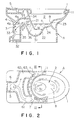
- Fig. 10 is a plan view including a partially cutaway portion and showing a fourth embodiment of the present invention.
- a water guide channel 64 for supplying flush water to the main flow discharging opening 7 and a water guide channel 65 for supplying flush water to the rim water path 1 are formed as separate independent passages.
- Forming the water guide channels 64 and 65 as separate independent passages allows the amount of flush water supplied to the main flow discharging opening 7 and the rim water path 1 to be distributed more precisely, providing efficient flushing and discharging actions.
- the guide part 8 is in the form of a protruding wall on the inner wall surface of the bowl part 2 facing the main flow discharging opening 7 and in the vicinity of the inlet 31 of the trap discharge passage.
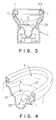
- Fig. 11 is a perspective view, partly in section, of an essential part of a fifth embodiment of the present invention.
- the guide part 8 is in the form of a wall protruding and rising from the inner wall surface of the bowl part 2 below and near the main flow discharging opening 7 below.
- the flush water discharged from the main flow discharging opening 7 directly collides with the guide part 8 and is guided toward the inlet 31 of the trap discharge passage, flowing powerfully from the inlet 31 into the trap discharge passage. This allows the trap discharge passage 3 to be filled sooner with water, thereby producing the siphoning action sooner.
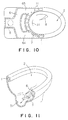
- Fig. 12 is a fragmentary perspective view showing an essential portion of a sixth embodiment of the invention.
- the guide part 8 is in the form of a groove from a position near the main flow discharging opening 7 toward the inlet 31 of the trap discharge passage.
- the flush water discharged from the main flow discharging opening 7 flows along the groove-like guide part 8 and is led into the inlet 31 of the trap discharge passage.
- the present embodiment also enables the siphoning action to be produced sooner in the way similar to the above-described embodiment.
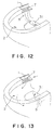
- Fig. 13 is a fragmentary perspective view showing an essential portion of a seventh embodiment of the present invention.
- the guide part 8 is in the form of a protruding and rising wall on the inner wall surface of the bowl part 2 at the side opposite the side of the main flow discharging opening 7 and at a position near the front end of the bowl part 2.
- the flush water discharged from the main flow discharging opening 7 flows down while rotating along the inner wall of the bowl part 2 and collides with the guide part 8, so that it is guided to the inlet 31 of the trap discharge passage. This allows the inner wall surface of the bowl part 2 to be powerfully flushed and, simultaneously, allows the siphoning action to be started sooner.
- Fig. 14 is a cross sectional view showing an eighth embodiment of the invention.
- the bowl part 2 has a steeply inclined surface 26 having a great angle of inclination formed so that the inner wall surface of the bowl part at any one of the left and right thereof comes to be steeply inclined compared with the other inner wall surface, and the inlet 31 of the trap discharge passage is provided at the side of the steeply inclined surface 26 in an off-centered relation.
- the steeply inclined surface 26 functions as a guide part for guiding flush water discharged from the main flow discharging opening 7, and allows flush water to flow smoothly into the trap discharge passage, thereby producing the siphoning action sooner.
- Fig. 15 is a plan view including a partially cutaway portion and showing a ninth embodiment of the invention.
- a plurality of projecting walls 68 extending from one of side walls in the replenishing water flow channel to the other wall are provided at predetermined intervals, and a narrow clearance "t" is formed between the other side wall and the ends of the projecting walls 68, so that a plurality of blind parts are formed to cause the flush water (replenishing water) flowing through the replenishing water guide channel 62 to stay in the blind parts 69, to thereby delay an arrival of the replenishing water at the rim water path 1, whereby a flow resistance means is constituted.
- an area of opening of the narrow clearance "t" in the replenishing water guide channel 62 formed by providing the above-described blind parts 69 should be an area which does not allow water film to spread after the replenishing water flows out, in the way similar to the above-described embodiment.
- Fig. 15 shows four blind parts 69, however, one blind part or blind parts less than four or more than four may be formed by changing the size, form and dimension of the blind parts suitably.
- the time to delay an arrival of the replenishing water at the rim water guide channel 1 is adjusted by suitably determining (increasing) the number of the blind parts 69, thereby ensuring the replenishing water more positively and allowing the effects of restoring the stored water within the bowl part as described above, to be made more effective.
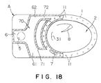
- Fig. 16 is a plan view including a partially cutaway view and showing a tenth embodiment of the invention.
- sectioned parts 66 and 67 are formed at both the left and right of the flush water guide channel 61 so that the flush water guide channel 61 is ensured in a direct connection from the water supply chamber 6 toward the rim water path 1 and, simultaneously, the replenishing water guide channel 62 is defined at the outside of one 62 of the sectioned parts so as to make a detour round the sectioned part 67 and communicate with the rim water path 1, so that the length of the replenishing water guide channel 62 is made longer than that of the flush water guide channel 61, thereby constituting a flow resistance means of delaying an arrival of the replenishing water at the rim water path 1.
- the means for making the length of the replenishing water guide channel 62 longer than the flush water guide channel 61 is not limited to what shown in the drawings, but arbitrary means are considered including defining the replenishing water guide channel 62 in the back of the water closet body A at a predetermined part thereof, for example, below the water supply chamber 6 or in the vicinity of the trap discharge passage, extending a portion of the replenishing water guide channel 62 outwardly of the water closet body A, and forming the replenishing water guide channel 62 per se spirally.
- the baffle board 63 and the narrow clearance "t" shown in Fig. 2 are formed in the vicinity of the outlet 62a of the replenishing water guide channel 62 so that the time to delay an arrival of the replenishing water at the rim water path 1 is suitably set; however, providing the baffle board 63 and the narrow clearance "t" in the present embodiment is not always required, and they may be arbitrarily provided corresponding to the length of the replenishing water guide channel 62, in other words, corresponding to the extent of delaying an arrival of the replenishing water at the rim water path 1.
- the flow resistance means in the present embodiment there is an advantage in that the time to delay an arrival of the replenishing water at the rim water path 1 can be adjusted by suitably determining (lengthening) the length of the replenishing water guide channel 62, thereby ensuring the replenishing water more positively and allowing the effects of restoring the stored water within the bowl part as described above, to be made more effective.
- the flow resistance means in the present embodiment is simple in construction and easy to manufacture, compared with the means of forming the replenishing water guide channel 62 below the water supply chamber 6 or in the vicinity of the trap water discharging channel, extending a portion thereof outwardly of the water closet body, and forming the replenishing water guide channel per se spirally.
- the replenishing water guide channel 62 is formed in a zigzag line so that the replenishing water flows therethrough in a zigzag direction, thereby constituting a flow resistance means of delaying an arrival of the replenishing water at the rim water path 1.
- the narrow clearances "t" in the replenishing water guide channel 62 formed by extending the replenishing water guide channel 62 in a zigzag line, i.e., the areas of openings of the bent portions in the zigzagged, replenishing water guide channel 62 should be areas to such a extent that water film does not spread after the replenishing water flows out, in the way similar to the above-described embodiment.
- the length of the replenishing water guide channel 62 is made longer by determining the zigzag pitch suitably, so that the time to delay an arrival of the replenishing water at the rim water path 1 is made longer, thereby ensuring the replenishing water more positively and allowing the effects of restoring the stored water within the bowl part as described above, to be made more effective.
- a sectioned part 71 which divides the downstream side of the water supply channel 70 into both the flush water guide channel 61 and the replenishing water guide channel 62, is extended in the direction of the replenishing water guide channel 62 to thereby reduce the diameter of the flow path at the downstream portion in the replenishing water guide channel 62 to form a narrow flow path 72, thereby constituting a flow resistance means of delaying an arrival of the replenishing water at the rim water path 1.
- the diameter of the narrow flow path 72 in the replenishing water guide channel 62 formed by providing the narrow flow path 72 is a diameter to such a degree that it does not allow water film to spread after the replenishing water flows out, in the way similar to the above-described embodiment.
- the narrow flow path 72 is formed at the downstream portion; however, the flow path diameter at the intermediate portion in the replenishing water guide channel 62 may be reduced to form the narrow flow path 72.
- the time to delay an arrival of the replenishing water at the rim water path 1 is made longer by suitably determining (lengthening) the length of the narrow flow path 72, thereby ensuring the replenishing water more positively and allowing the effects of restoring the stored water within the bowl part as described above, to be made more effective.
- the siphoning jet type of water closet is provided with a construction of injecting the main flow from the interior of the stored water toward the inlet of the trap discharge passage, none of the main flow discharging opening 7 provided at a level above the stored water surface and the guide part 8 for guiding the main flow to the trap discharge passage are required.
- the siphoning jet type of water closet serves the purpose also in the case where a raised position "b" in water level required to produce the siphoning action is lower, compared with the siphoning type of water closet described in the embodiments, the upper end of the portion 23 in which the wall surface within the bowl part rises in a nearly vertically position may be lower than that of the siphoning type of water closet.
- the present invention allows the descending passage of the trap discharge passage to be filled sooner with water, thereby enabling the siphoning action to be produced in the trap discharge passage sooner.
- the present invention further allows the flush water supplied from the water supply part to be efficiently used for flushing and discharging operation, thereby enabling the flush water to be saved.
- the stored water can be surely restored to a predetermined position within the bowl part without being affected by a change in water pressure at the inlet side of a ball tap, a flush valve and the like of the water supply tank.
Landscapes
- Health & Medical Sciences (AREA)
- Life Sciences & Earth Sciences (AREA)
- Engineering & Computer Science (AREA)
- Hydrology & Water Resources (AREA)
- Public Health (AREA)
- Water Supply & Treatment (AREA)
- Sanitary Device For Flush Toilet (AREA)
Applications Claiming Priority (3)
| Application Number | Priority Date | Filing Date | Title |
|---|---|---|---|
| JP11889694A JP3538894B2 (ja) | 1994-05-31 | 1994-05-31 | サイホン式水洗便器 |
| JP118896/94 | 1994-05-31 | ||
| PCT/JP1995/000995 WO1995033103A1 (fr) | 1994-05-31 | 1995-05-24 | Siege de w-c a chasse d'eau |
Publications (1)
| Publication Number | Publication Date |
|---|---|
| EP0712967A1 true EP0712967A1 (fr) | 1996-05-22 |
Family
ID=14747850
Family Applications (1)
| Application Number | Title | Priority Date | Filing Date |
|---|---|---|---|
| EP95919626A Withdrawn EP0712967A1 (fr) | 1994-05-31 | 1995-05-24 | Siege de w-c a chasse d'eau |
Country Status (5)
| Country | Link |
|---|---|
| EP (1) | EP0712967A1 (fr) |
| JP (1) | JP3538894B2 (fr) |
| CA (1) | CA2168235A1 (fr) |
| TW (1) | TW276285B (fr) |
| WO (1) | WO1995033103A1 (fr) |
Cited By (2)
| Publication number | Priority date | Publication date | Assignee | Title |
|---|---|---|---|---|
| JP2015206179A (ja) * | 2014-04-18 | 2015-11-19 | 株式会社Lixil | 水洗式便器 |
| CN112575860A (zh) * | 2019-09-27 | 2021-03-30 | Toto株式会社 | 冲水大便器 |
Families Citing this family (12)
| Publication number | Priority date | Publication date | Assignee | Title |
|---|---|---|---|---|
| JP4782628B2 (ja) * | 2006-07-13 | 2011-09-28 | 株式会社ブリヂストン | サイフォン排水システム |
| JP5715402B2 (ja) * | 2010-12-15 | 2015-05-07 | 株式会社Lixil | 水洗式便器の排水路 |
| JP5826485B2 (ja) * | 2010-02-01 | 2015-12-02 | 株式会社Lixil | 水洗式便器 |
| JP5715403B2 (ja) * | 2010-12-15 | 2015-05-07 | 株式会社Lixil | 水洗式便器の排水路 |
| WO2011093440A1 (fr) * | 2010-02-01 | 2011-08-04 | 株式会社Lixil | Canal de drainage de toilette à chasse d'eau |
| JP5841343B2 (ja) * | 2011-03-25 | 2016-01-13 | 株式会社Lixil | 水洗式便器 |
| JP5885119B2 (ja) * | 2011-08-05 | 2016-03-15 | Toto株式会社 | 水洗大便器 |
| JP6037267B2 (ja) * | 2011-09-21 | 2016-12-07 | パナソニックIpマネジメント株式会社 | 水洗便器 |
| JP5831847B2 (ja) * | 2012-02-22 | 2015-12-09 | Toto株式会社 | サイホン式大便器 |
| JP6025531B2 (ja) * | 2012-11-30 | 2016-11-16 | アロン化成株式会社 | 吸引式便器 |
| JP6242140B2 (ja) * | 2013-10-04 | 2017-12-06 | 株式会社Lixil | 汚物排出装置 |
| JP2016148218A (ja) * | 2015-02-13 | 2016-08-18 | パナソニックIpマネジメント株式会社 | 水洗便器 |
Family Cites Families (2)
| Publication number | Priority date | Publication date | Assignee | Title |
|---|---|---|---|---|
| JPH0735891Y2 (ja) * | 1989-07-31 | 1995-08-16 | 株式会社イナックス | 水洗便器 |
| JP2845351B2 (ja) * | 1991-01-09 | 1999-01-13 | 東陶機器株式会社 | 水洗式便器 |
-
1994
- 1994-05-31 JP JP11889694A patent/JP3538894B2/ja not_active Expired - Lifetime
-
1995
- 1995-05-24 WO PCT/JP1995/000995 patent/WO1995033103A1/fr not_active Application Discontinuation
- 1995-05-24 EP EP95919626A patent/EP0712967A1/fr not_active Withdrawn
- 1995-05-24 CA CA002168235A patent/CA2168235A1/fr not_active Abandoned
- 1995-05-30 TW TW84105453A patent/TW276285B/zh active
Non-Patent Citations (1)
| Title |
|---|
| See references of WO9533103A1 * |
Cited By (2)
| Publication number | Priority date | Publication date | Assignee | Title |
|---|---|---|---|---|
| JP2015206179A (ja) * | 2014-04-18 | 2015-11-19 | 株式会社Lixil | 水洗式便器 |
| CN112575860A (zh) * | 2019-09-27 | 2021-03-30 | Toto株式会社 | 冲水大便器 |
Also Published As
| Publication number | Publication date |
|---|---|
| JP3538894B2 (ja) | 2004-06-14 |
| WO1995033103A1 (fr) | 1995-12-07 |
| JPH07324367A (ja) | 1995-12-12 |
| TW276285B (en) | 1996-05-21 |
| CA2168235A1 (fr) | 1995-12-01 |
Similar Documents
| Publication | Publication Date | Title |
|---|---|---|
| EP0712967A1 (fr) | Siege de w-c a chasse d'eau | |
| US7661153B2 (en) | Flush toilet | |
| KR100256323B1 (ko) | 수세식대변기 | |
| US9303395B2 (en) | Flush toilet | |
| CN107201776B (zh) | 冲水大便器 | |
| JP4406920B2 (ja) | 水洗便器 | |
| JP4702922B2 (ja) | 水洗便器 | |
| EP0407609A1 (fr) | Cuvette de w.-c. a chasse d'eau | |
| CA2157044A1 (fr) | W.c. | |
| JP6880470B2 (ja) | 水洗大便器 | |
| JP3216421B2 (ja) | 水洗式便器 | |
| US9995029B2 (en) | Flush toilet having rim slot of varying width | |
| CN107849841B (zh) | 抽水马桶 | |
| JP3593620B2 (ja) | 便器と排便管接続用の排水ソケット | |
| US11072920B2 (en) | Flush toilet | |
| JP2003129550A (ja) | 大便器 | |
| JP2710791B2 (ja) | 水洗式便器 | |
| JP6718587B2 (ja) | 水洗大便器 | |
| JPH09177161A (ja) | 水洗便器 | |
| JP2002173969A (ja) | 水洗式便器 | |
| JPH09195366A (ja) | サイホン式洋風便器 | |
| JPH10237928A (ja) | 水洗便器 | |
| JP2023102353A (ja) | 水洗式便器 | |
| JPH0218133Y2 (fr) | ||
| JP5715404B2 (ja) | 水洗式便器の排水路 |
Legal Events
| Date | Code | Title | Description |
|---|---|---|---|
| PUAI | Public reference made under article 153(3) epc to a published international application that has entered the european phase |
Free format text: ORIGINAL CODE: 0009012 |
|
| 17P | Request for examination filed |
Effective date: 19960208 |
|
| AK | Designated contracting states |
Kind code of ref document: A1 Designated state(s): AT BE CH DE DK ES FR GB GR IE IT LI LU MC NL PT SE |
|
| STAA | Information on the status of an ep patent application or granted ep patent |
Free format text: STATUS: THE APPLICATION IS DEEMED TO BE WITHDRAWN |
|
| 18D | Application deemed to be withdrawn |
Effective date: 19971201 |