EP0712207A2 - Leistungsversorgung zur zeitlichen Stromversorgung nach dem Sperren - Google Patents
Leistungsversorgung zur zeitlichen Stromversorgung nach dem Sperren Download PDFInfo
- Publication number
- EP0712207A2 EP0712207A2 EP95111108A EP95111108A EP0712207A2 EP 0712207 A2 EP0712207 A2 EP 0712207A2 EP 95111108 A EP95111108 A EP 95111108A EP 95111108 A EP95111108 A EP 95111108A EP 0712207 A2 EP0712207 A2 EP 0712207A2
- Authority
- EP
- European Patent Office
- Prior art keywords
- power
- power supply
- switch
- circuit
- loss
- Prior art date
- Legal status (The legal status is an assumption and is not a legal conclusion. Google has not performed a legal analysis and makes no representation as to the accuracy of the status listed.)
- Granted
Links
Images
Classifications
-
- G—PHYSICS
- G03—PHOTOGRAPHY; CINEMATOGRAPHY; ANALOGOUS TECHNIQUES USING WAVES OTHER THAN OPTICAL WAVES; ELECTROGRAPHY; HOLOGRAPHY
- G03G—ELECTROGRAPHY; ELECTROPHOTOGRAPHY; MAGNETOGRAPHY
- G03G15/00—Apparatus for electrographic processes using a charge pattern
- G03G15/80—Details relating to power supplies, circuits boards, electrical connections
-
- G—PHYSICS
- G03—PHOTOGRAPHY; CINEMATOGRAPHY; ANALOGOUS TECHNIQUES USING WAVES OTHER THAN OPTICAL WAVES; ELECTROGRAPHY; HOLOGRAPHY
- G03G—ELECTROGRAPHY; ELECTROPHOTOGRAPHY; MAGNETOGRAPHY
- G03G21/00—Arrangements not provided for by groups G03G13/00 - G03G19/00, e.g. cleaning, elimination of residual charge
- G03G21/20—Humidity or temperature control also ozone evacuation; Internal apparatus environment control
- G03G21/206—Conducting air through the machine, e.g. for cooling, filtering, removing gases like ozone
-
- H—ELECTRICITY
- H02—GENERATION; CONVERSION OR DISTRIBUTION OF ELECTRIC POWER
- H02J—ELECTRIC POWER NETWORKS; CIRCUIT ARRANGEMENTS OR SYSTEMS FOR SUPPLYING OR DISTRIBUTING ELECTRIC POWER; SYSTEMS FOR STORING ELECTRIC ENERGY
- H02J9/00—Circuit arrangements for emergency or stand-by power supply, e.g. for emergency lighting
-
- H—ELECTRICITY
- H03—ELECTRONIC CIRCUITRY
- H03K—PULSE TECHNIQUE
- H03K17/00—Electronic switching or gating, i.e. not by contact-making and –breaking
- H03K17/28—Modifications for introducing a time delay before switching
- H03K17/292—Modifications for introducing a time delay before switching in thyristor, unijunction transistor or programmable unijunction transistor switches
-
- H—ELECTRICITY
- H03—ELECTRONIC CIRCUITRY
- H03K—PULSE TECHNIQUE
- H03K17/00—Electronic switching or gating, i.e. not by contact-making and –breaking
- H03K17/51—Electronic switching or gating, i.e. not by contact-making and –breaking characterised by the components used
- H03K17/56—Electronic switching or gating, i.e. not by contact-making and –breaking characterised by the components used by the use, as active elements, of semiconductor devices
- H03K17/687—Electronic switching or gating, i.e. not by contact-making and –breaking characterised by the components used by the use, as active elements, of semiconductor devices the devices being field-effect transistors
- H03K17/689—Electronic switching or gating, i.e. not by contact-making and –breaking characterised by the components used by the use, as active elements, of semiconductor devices the devices being field-effect transistors with galvanic isolation between the control circuit and the output circuit
Definitions
- This invention relates to an improved laser printer power supply that maintains 24 volt power to run exhaust fans for a brief period after the power switch is turned off. These fans remove undesirable ozone from the photo conducting print drum so as to extend the life of the photo conductor.
- Certain state-of-the-art laser printers presently utilize power supplies composed of a switching power supply combined with an auxiliary power supply.
- the switching power supply is used to provide the primary direct current (DC) voltages that the laser printer operates on.
- the switching power supply provides three operating voltages for the printer, +5 volts, +12 volts, and +24 volts. These are standard voltages with +5 volts used for the control computer, +12 volts used for analog circuitry, and +24 volts used for powering cooling fans, electric motors, electromechanical relays, and solenoids.
- the auxiliary power supply provides +22 volts and is used to power exhaust fans after the switching power supply has been turned off.
- the exhaust fans are powered for a short time after the printer has been turned off to vent ozone from the photo conducting print drum. Ozone generated from the printing process attacks the outer surface of the photo conductor and decreases the useful life of the photo conductor.
- An electronic time delay senses loss of 24 volts DC and starts timing to allow the auxiliary power supply to operate for approximately three minutes to ensure that the ozone is sufficiently vented from the photo conductor.
- auxiliary power supply utilizing +120v AC or +240v AC and supplying +22v DC requires a bulky transformer.
- the auxiliary power supply is always connected to the AC line which results in constant power consumption when the printed is turned off and higher power consumption when the printer is turned on. This higher power consumption results in higher operating temperatures within the printer power supplies, thereby requiring an extra 2-watt DC power supply cooling fan.
- the power consumption of the auxiliary power supply when plugged into 120v AC is about 2 watts. Future regulatory requirements, both voluntary and non-voluntary will require a lower "turned off" power consumption.
- This invention is for a power supply for providing timed residual power after turn off comprising: an AC power switching device providing voltage to AC and DC power circuits; a timer circuit activated by a loss of AC power from an AC power switch; an optically isolated photo-diac having an output from the timer circuit coupled to the AC power switching device; a load switch driver circuit having an input from the power switch and having an opto-coupler output to a load switch circuit; wherein the loss of AC power from the AC power switch causes the timer circuit to continue to provide power to the AC and DC power circuits and to activate the load switch circuit.
- the power supply does not require the load switch driver or load switch circuit.
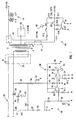
- Figure 1 is an electrical schematic of an improved printer power supply and timer of the present invention.
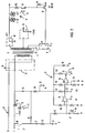
- Figure 2 is an electrical schematic of an improved printer power supply and timer without a load switch on the +5v DC circuit.
- Figure 1 illustrates the circuit modifications of the present invention that permit deleting the auxiliary power supply and the DC power supply cooling fan of the prior art.
- the AC line switching function is performed by an AC power switching device 29 comprising triac 30 which is controlled by optically isolated photo-diac 31 and 32.
- This photo-diac shown as a Light Emitting Diode (LED) 31 in the timer circuit 34 and as a pair of back-to-back diodes 32 connecting at triac 30 is actually a single component that is optically coupled by internal light beam 33.
- a triac is a thyristor that can be triggered to conduct in either direction or, if non-triggered, possesses symmetrical bidirectional blocking voltage capabilities. In this case, the triggering comes from the operational amplifier timing circuit 34 that can provide a three-to-four-minute time delay via the optically isolated photo-diac 31 and 32.
- Time delay circuit 34 consists of a first op-amp (comparator) 36 and a second op-amp 38. These op-amps 36 and 38 are open collector types.
- a load switch 40 provides a load, 10 ohm resistor R15, on the 5 volt power supply 41 so that the 5v DC is regulated properly when the rest of the printer is off and only the 24 v DC exhaust fans 14 are running.
- the 5 volt load also keeps the 12v and 24v supplies, 42 and 44 respectively, at their proper voltage at this same time.
- This load switch is activated by light 46 from load switch drive circuit 48.
- Drive circuit 48 has one-half of an opto-coupler Q4, appearing as a light emitting diode, and is coupled by internal light 46 to the transistor device Q4 in the load switch 40.
- Opto-coupler Q4 turns OFF Q3 and Q1, turning Q2 ON to load R15.
- the power sense comparator 36 compares the voltage at the anode of Q4 to a reference formed by R6 and R11. As long as S1 remains closed, the voltage at the negative terminal of the comparator 36 is greater than the voltage at the positive terminal and the open collector outputs of the comparator 36 keep the timing circuit R7 and C3 discharged.
- the timing comparator 38 compares the voltage at the positive terminal from C3 to a reference formed by R8 and R12 at the negative terminal. As long as the voltage on the negative terminal is greater than the positive terminal, LED 31 is conducting and emitting light 33 to turn on the photo-diac 32 which keeps the triac 30 turned on and supplying AC current to the switching power supply front end 24.
- the power sense comparator 36 allows C3 of the timing circuit 34 to be charged by R7 starting the 3.5 minute power time delay of timing circuit 34.
- the comparator turns OFF opto-coupler 31 and 32 which then causes the triac 30 to turn OFF and AC current is no longer supplied to the switching power supply front end 24.
- Components in the component list have been selected such that the timing comparator 38 allows the printer exhaust fans 14 to remain on for about 3.5 minutes. Further, D1 stops conducting, C2 discharges, and the comparators turn OFF. The printer is now fully turned OFF and essentially draws no power, i.e., less than .06 watts in circuitry not associated with the supply.
- the load switch 40 may not be necessary. Use of a load switch depends only on the minimum loading necessary to stabilize the outputs of the 24v, 12v, and 5v voltage regulators 44, 42, and 41, respectively, as seen in Figure 2. In this case, the load switch 40 ( Figure 1) is not used and only Q4, R13, R14, and Q3 are needed to turn off the +5v digital circuit supply.
Landscapes
- Engineering & Computer Science (AREA)
- General Physics & Mathematics (AREA)
- Physics & Mathematics (AREA)
- Environmental Sciences (AREA)
- Atmospheric Sciences (AREA)
- Biodiversity & Conservation Biology (AREA)
- Ecology (AREA)
- Environmental & Geological Engineering (AREA)
- Life Sciences & Earth Sciences (AREA)
- Business, Economics & Management (AREA)
- Emergency Management (AREA)
- Power Engineering (AREA)
- Control Or Security For Electrophotography (AREA)
- Rectifiers (AREA)
- Control Of Voltage And Current In General (AREA)
- Accessory Devices And Overall Control Thereof (AREA)
Applications Claiming Priority (2)
| Application Number | Priority Date | Filing Date | Title |
|---|---|---|---|
| US338710 | 1994-11-14 | ||
| US08/338,710 US5541458A (en) | 1994-11-14 | 1994-11-14 | Power supply for timed residual power after turn off |
Publications (3)
| Publication Number | Publication Date |
|---|---|
| EP0712207A2 true EP0712207A2 (de) | 1996-05-15 |
| EP0712207A3 EP0712207A3 (de) | 1996-09-25 |
| EP0712207B1 EP0712207B1 (de) | 2004-09-29 |
Family
ID=23325839
Family Applications (1)
| Application Number | Title | Priority Date | Filing Date |
|---|---|---|---|
| EP95111108A Expired - Lifetime EP0712207B1 (de) | 1994-11-14 | 1995-07-14 | Leistungsversorgung zur zeitlichen Stromversorgung nach dem Sperren |
Country Status (4)
| Country | Link |
|---|---|
| US (1) | US5541458A (de) |
| EP (1) | EP0712207B1 (de) |
| JP (1) | JP3628784B2 (de) |
| DE (1) | DE69533572T2 (de) |
Cited By (2)
| Publication number | Priority date | Publication date | Assignee | Title |
|---|---|---|---|---|
| GB2519851A (en) * | 2013-09-05 | 2015-05-06 | Canon Kk | Information processing apparatus and power-supply control method for information processing apparatus |
| CN102694532B (zh) * | 2012-06-06 | 2016-09-28 | 兰莉莉 | 节能控制装置 |
Families Citing this family (9)
| Publication number | Priority date | Publication date | Assignee | Title |
|---|---|---|---|---|
| KR0180801B1 (ko) * | 1995-11-30 | 1999-05-15 | 김광호 | 전원 공급의 자동 차단을 위한 제어 장치 |
| FR2775364B1 (fr) * | 1998-02-20 | 2003-06-20 | Crouzet Automatismes | Procede de commande par angle de phase |
| HK1040944B (en) * | 1998-10-23 | 2007-09-07 | Amgen Inc. | Methods and compositions for the prevention and treatment of anemia |
| US6538345B1 (en) | 2000-10-24 | 2003-03-25 | Trombetta, Llc | Load bank alternating current regulating control |
| US6661123B2 (en) * | 2001-12-17 | 2003-12-09 | Mitac International Corp. | Power control circuit with power-off time delay control for microprocessor-based system |
| US6908164B2 (en) * | 2003-01-13 | 2005-06-21 | Lexmark International, Inc. | Power control circuit for printers and other devices |
| CN102445911B (zh) * | 2011-11-23 | 2016-05-04 | 兰莉莉 | 电路简单的节能控制开关 |
| JP2015125429A (ja) * | 2013-12-27 | 2015-07-06 | キヤノン株式会社 | 画像形成装置、画像形成装置の制御方法、及びプログラム |
| CN104184442B (zh) * | 2014-08-05 | 2018-01-09 | 衢州迪升工业设计有限公司 | 由关门信息触发的冰箱除臭保鲜器电路 |
Family Cites Families (8)
| Publication number | Priority date | Publication date | Assignee | Title |
|---|---|---|---|---|
| US4384213A (en) * | 1976-07-19 | 1983-05-17 | Westinghouse Electric Corp. | Automatic transfer control device |
| US4521693A (en) * | 1983-02-11 | 1985-06-04 | Johnson Alan L | Electro-optical solid-state SPDT relay switch |
| JPS60201364A (ja) * | 1984-03-26 | 1985-10-11 | Konishiroku Photo Ind Co Ltd | 複写装置 |
| JPS62225194A (ja) * | 1986-03-27 | 1987-10-03 | Mitsubishi Electric Corp | フアンモ−タ通電制御回路 |
| JPH01200375A (ja) * | 1988-02-05 | 1989-08-11 | Minolta Camera Co Ltd | 複写機 |
| DE3943193C2 (de) * | 1989-12-28 | 1999-06-10 | Kutzner & Weber Gmbh | Belüftungseinrichtung für einen Raum mit Feuerstelle |
| US5144364A (en) * | 1990-03-22 | 1992-09-01 | Tokyo Electric Co., Ltd. | Power supply for electrophotography apparatus |
| JP3088769B2 (ja) * | 1991-04-18 | 2000-09-18 | 株式会社リコー | 画像形成装置 |
-
1994
- 1994-11-14 US US08/338,710 patent/US5541458A/en not_active Expired - Lifetime
-
1995
- 1995-07-14 EP EP95111108A patent/EP0712207B1/de not_active Expired - Lifetime
- 1995-07-14 DE DE69533572T patent/DE69533572T2/de not_active Expired - Fee Related
- 1995-11-14 JP JP31957995A patent/JP3628784B2/ja not_active Expired - Fee Related
Non-Patent Citations (1)
| Title |
|---|
| None |
Cited By (4)
| Publication number | Priority date | Publication date | Assignee | Title |
|---|---|---|---|---|
| CN102694532B (zh) * | 2012-06-06 | 2016-09-28 | 兰莉莉 | 节能控制装置 |
| GB2519851A (en) * | 2013-09-05 | 2015-05-06 | Canon Kk | Information processing apparatus and power-supply control method for information processing apparatus |
| GB2519851B (en) * | 2013-09-05 | 2016-06-01 | Canon Kk | Image forming apparatus and power-supply control method for image forming apparatus |
| US9785874B2 (en) | 2013-09-05 | 2017-10-10 | Canon Kabushiki Kaisha | Information processing apparatus and power-supply control method for information processing apparatus that interrupt power supply to a printing unit based on elapsing of a first time period and that interrupt power supply to a control unit based on elapsing of a second time period |
Also Published As
| Publication number | Publication date |
|---|---|
| JPH08256478A (ja) | 1996-10-01 |
| EP0712207A3 (de) | 1996-09-25 |
| EP0712207B1 (de) | 2004-09-29 |
| DE69533572T2 (de) | 2005-10-06 |
| US5541458A (en) | 1996-07-30 |
| DE69533572D1 (de) | 2004-11-04 |
| JP3628784B2 (ja) | 2005-03-16 |
Similar Documents
| Publication | Publication Date | Title |
|---|---|---|
| EP0712207A2 (de) | Leistungsversorgung zur zeitlichen Stromversorgung nach dem Sperren | |
| HK79996A (en) | A power supply circuit | |
| US6230710B1 (en) | Electrical power system for a self-contained transportable life support system | |
| JPH04185297A (ja) | モータの給電回路 | |
| JPH02294277A (ja) | スイッチング電源装置用初期パワーアップ装置 | |
| US6952085B2 (en) | Continuous mode ballast with pulsed operation | |
| US20050012468A1 (en) | Scanning apparatus having a fluorescent lamp and control method thereof | |
| US7521820B2 (en) | Electrical apparatus system | |
| JP2865085B2 (ja) | 突入電流防止回路 | |
| JP2000232729A (ja) | 電源装置及び電源供給システム | |
| HU191025B (en) | Cicuit arrangement for supplying the control electronics of current convertors of forced commutation with current | |
| EP0827264A3 (de) | Schaltnetzteil | |
| US6975076B2 (en) | Charge pump circuit to operate control circuit | |
| JPH06284571A (ja) | 突入電流防止回路 | |
| JPH0713433Y2 (ja) | 高周波発振器用直流電源回路 | |
| JP2639652B2 (ja) | アーク加工装置 | |
| ES2133505T3 (es) | Dispositivo de limitacion de corriente del tipo colocado entre una tarjeta electronica y medios de alimentacion. | |
| KR880002194Y1 (ko) | 전원 차단시 모우터 원상복귀회로 | |
| JP2536495B2 (ja) | 電源装置 | |
| EP0234413A3 (en) | Circuit arrangement for current supply | |
| WO2000025413A1 (en) | Switch mode and computer power supply with a method of its controlling | |
| JPH03159567A (ja) | 直流電源装置 | |
| JP2829990B2 (ja) | 車両用充電制御装置 | |
| JPH07303336A (ja) | 電子回路 | |
| JPH01117690A (ja) | 送風機制御装置 |
Legal Events
| Date | Code | Title | Description |
|---|---|---|---|
| PUAI | Public reference made under article 153(3) epc to a published international application that has entered the european phase |
Free format text: ORIGINAL CODE: 0009012 |
|
| AK | Designated contracting states |
Kind code of ref document: A2 Designated state(s): DE FR GB |
|
| PUAL | Search report despatched |
Free format text: ORIGINAL CODE: 0009013 |
|
| AK | Designated contracting states |
Kind code of ref document: A3 Designated state(s): DE FR GB |
|
| 17P | Request for examination filed |
Effective date: 19970321 |
|
| RAP1 | Party data changed (applicant data changed or rights of an application transferred) |
Owner name: HEWLETT-PACKARD COMPANY, A DELAWARE CORPORATION |
|
| 17Q | First examination report despatched |
Effective date: 20030923 |
|
| GRAP | Despatch of communication of intention to grant a patent |
Free format text: ORIGINAL CODE: EPIDOSNIGR1 |
|
| GRAS | Grant fee paid |
Free format text: ORIGINAL CODE: EPIDOSNIGR3 |
|
| GRAA | (expected) grant |
Free format text: ORIGINAL CODE: 0009210 |
|
| AK | Designated contracting states |
Kind code of ref document: B1 Designated state(s): DE FR GB |
|
| REG | Reference to a national code |
Ref country code: GB Ref legal event code: FG4D |
|
| REF | Corresponds to: |
Ref document number: 69533572 Country of ref document: DE Date of ref document: 20041104 Kind code of ref document: P |
|
| ET | Fr: translation filed | ||
| PLBE | No opposition filed within time limit |
Free format text: ORIGINAL CODE: 0009261 |
|
| STAA | Information on the status of an ep patent application or granted ep patent |
Free format text: STATUS: NO OPPOSITION FILED WITHIN TIME LIMIT |
|
| 26N | No opposition filed |
Effective date: 20050630 |
|
| PGFP | Annual fee paid to national office [announced via postgrant information from national office to epo] |
Ref country code: DE Payment date: 20070831 Year of fee payment: 13 |
|
| PGFP | Annual fee paid to national office [announced via postgrant information from national office to epo] |
Ref country code: FR Payment date: 20070717 Year of fee payment: 13 |
|
| PG25 | Lapsed in a contracting state [announced via postgrant information from national office to epo] |
Ref country code: DE Free format text: LAPSE BECAUSE OF NON-PAYMENT OF DUE FEES Effective date: 20090203 |
|
| REG | Reference to a national code |
Ref country code: FR Ref legal event code: ST Effective date: 20090331 |
|
| PG25 | Lapsed in a contracting state [announced via postgrant information from national office to epo] |
Ref country code: FR Free format text: LAPSE BECAUSE OF NON-PAYMENT OF DUE FEES Effective date: 20080731 |
|
| REG | Reference to a national code |
Ref country code: GB Ref legal event code: 732E Free format text: REGISTERED BETWEEN 20120329 AND 20120404 |
|
| PGFP | Annual fee paid to national office [announced via postgrant information from national office to epo] |
Ref country code: GB Payment date: 20130626 Year of fee payment: 19 |
|
| GBPC | Gb: european patent ceased through non-payment of renewal fee |
Effective date: 20140714 |
|
| PG25 | Lapsed in a contracting state [announced via postgrant information from national office to epo] |
Ref country code: GB Free format text: LAPSE BECAUSE OF NON-PAYMENT OF DUE FEES Effective date: 20140714 |