EP0711603B1 - System zur Inkubation von Probeflüssigkeiten - Google Patents
System zur Inkubation von Probeflüssigkeiten Download PDFInfo
- Publication number
- EP0711603B1 EP0711603B1 EP95117563A EP95117563A EP0711603B1 EP 0711603 B1 EP0711603 B1 EP 0711603B1 EP 95117563 A EP95117563 A EP 95117563A EP 95117563 A EP95117563 A EP 95117563A EP 0711603 B1 EP0711603 B1 EP 0711603B1
- Authority
- EP
- European Patent Office
- Prior art keywords
- incubation
- block
- vessels
- holding plate
- holes
- Prior art date
- Legal status (The legal status is an assumption and is not a legal conclusion. Google has not performed a legal analysis and makes no representation as to the accuracy of the status listed.)
- Expired - Lifetime
Links
Images

Classifications
-
- B—PERFORMING OPERATIONS; TRANSPORTING
- B01—PHYSICAL OR CHEMICAL PROCESSES OR APPARATUS IN GENERAL
- B01L—CHEMICAL OR PHYSICAL LABORATORY APPARATUS FOR GENERAL USE
- B01L3/00—Containers or dishes for laboratory use, e.g. laboratory glassware; Droppers
- B01L3/50—Containers for the purpose of retaining a material to be analysed, e.g. test tubes
- B01L3/508—Rigid containers without fluid transport within
- B01L3/5085—Rigid containers without fluid transport within for multiple samples, e.g. microtitration plates
- B01L3/50851—Rigid containers without fluid transport within for multiple samples, e.g. microtitration plates specially adapted for heating or cooling samples
-
- B—PERFORMING OPERATIONS; TRANSPORTING
- B01—PHYSICAL OR CHEMICAL PROCESSES OR APPARATUS IN GENERAL
- B01L—CHEMICAL OR PHYSICAL LABORATORY APPARATUS FOR GENERAL USE
- B01L7/00—Heating or cooling apparatus; Heat insulating devices
- B01L7/52—Heating or cooling apparatus; Heat insulating devices with provision for submitting samples to a predetermined sequence of different temperatures, e.g. for treating nucleic acid samples
-
- Y—GENERAL TAGGING OF NEW TECHNOLOGICAL DEVELOPMENTS; GENERAL TAGGING OF CROSS-SECTIONAL TECHNOLOGIES SPANNING OVER SEVERAL SECTIONS OF THE IPC; TECHNICAL SUBJECTS COVERED BY FORMER USPC CROSS-REFERENCE ART COLLECTIONS [XRACs] AND DIGESTS
- Y10—TECHNICAL SUBJECTS COVERED BY FORMER USPC
- Y10S—TECHNICAL SUBJECTS COVERED BY FORMER USPC CROSS-REFERENCE ART COLLECTIONS [XRACs] AND DIGESTS
- Y10S435/00—Chemistry: molecular biology and microbiology
- Y10S435/809—Incubators or racks or holders for culture plates or containers
-
- Y—GENERAL TAGGING OF NEW TECHNOLOGICAL DEVELOPMENTS; GENERAL TAGGING OF CROSS-SECTIONAL TECHNOLOGIES SPANNING OVER SEVERAL SECTIONS OF THE IPC; TECHNICAL SUBJECTS COVERED BY FORMER USPC CROSS-REFERENCE ART COLLECTIONS [XRACs] AND DIGESTS
- Y10—TECHNICAL SUBJECTS COVERED BY FORMER USPC
- Y10S—TECHNICAL SUBJECTS COVERED BY FORMER USPC CROSS-REFERENCE ART COLLECTIONS [XRACs] AND DIGESTS
- Y10S436/00—Chemistry: analytical and immunological testing
- Y10S436/807—Apparatus included in process claim, e.g. physical support structures
-
- Y—GENERAL TAGGING OF NEW TECHNOLOGICAL DEVELOPMENTS; GENERAL TAGGING OF CROSS-SECTIONAL TECHNOLOGIES SPANNING OVER SEVERAL SECTIONS OF THE IPC; TECHNICAL SUBJECTS COVERED BY FORMER USPC CROSS-REFERENCE ART COLLECTIONS [XRACs] AND DIGESTS
- Y10—TECHNICAL SUBJECTS COVERED BY FORMER USPC
- Y10S—TECHNICAL SUBJECTS COVERED BY FORMER USPC CROSS-REFERENCE ART COLLECTIONS [XRACs] AND DIGESTS
- Y10S436/00—Chemistry: analytical and immunological testing
- Y10S436/807—Apparatus included in process claim, e.g. physical support structures
- Y10S436/809—Multifield plates or multicontainer arrays
-
- Y—GENERAL TAGGING OF NEW TECHNOLOGICAL DEVELOPMENTS; GENERAL TAGGING OF CROSS-SECTIONAL TECHNOLOGIES SPANNING OVER SEVERAL SECTIONS OF THE IPC; TECHNICAL SUBJECTS COVERED BY FORMER USPC CROSS-REFERENCE ART COLLECTIONS [XRACs] AND DIGESTS
- Y10—TECHNICAL SUBJECTS COVERED BY FORMER USPC
- Y10S—TECHNICAL SUBJECTS COVERED BY FORMER USPC CROSS-REFERENCE ART COLLECTIONS [XRACs] AND DIGESTS
- Y10S436/00—Chemistry: analytical and immunological testing
- Y10S436/807—Apparatus included in process claim, e.g. physical support structures
- Y10S436/81—Tube, bottle, or dipstick
-
- Y—GENERAL TAGGING OF NEW TECHNOLOGICAL DEVELOPMENTS; GENERAL TAGGING OF CROSS-SECTIONAL TECHNOLOGIES SPANNING OVER SEVERAL SECTIONS OF THE IPC; TECHNICAL SUBJECTS COVERED BY FORMER USPC CROSS-REFERENCE ART COLLECTIONS [XRACs] AND DIGESTS
- Y10—TECHNICAL SUBJECTS COVERED BY FORMER USPC
- Y10T—TECHNICAL SUBJECTS COVERED BY FORMER US CLASSIFICATION
- Y10T436/00—Chemistry: analytical and immunological testing
- Y10T436/11—Automated chemical analysis
-
- Y—GENERAL TAGGING OF NEW TECHNOLOGICAL DEVELOPMENTS; GENERAL TAGGING OF CROSS-SECTIONAL TECHNOLOGIES SPANNING OVER SEVERAL SECTIONS OF THE IPC; TECHNICAL SUBJECTS COVERED BY FORMER USPC CROSS-REFERENCE ART COLLECTIONS [XRACs] AND DIGESTS
- Y10—TECHNICAL SUBJECTS COVERED BY FORMER USPC
- Y10T—TECHNICAL SUBJECTS COVERED BY FORMER US CLASSIFICATION
- Y10T436/00—Chemistry: analytical and immunological testing
- Y10T436/25—Chemistry: analytical and immunological testing including sample preparation
Definitions
- sample liquids are not used exclusively for performing an analytical Reaction used, rather incubators are also used to in Sample liquids of existing organisms such as bacteria, yeast, fungi, viruses etc. to multiply in order to subsequently be able to determine the multiplicated organisms. Incubators are also used, for example, to multiply DNA or RNA. The corresponding devices are called thermal cyclers.
- the known devices can basically be divided into two classes become.
- the first class includes such incubators, in which the sample vessels be heated by a fluid phase.
- Devices of this type are for example in EP-A-0 363 143 and EP-B-0 087 028.
- the sample vessels or sample liquids are tempered by the liquid inside the incubator. Due to the fluid properties of the liquid phase, the liquid adapts perfectly to the shape of the incubation vessels.
- the second class of incubation devices includes so-called metal block incubators, in which within an incubation block of thermally conductive Material holes are located, which are used to hold incubation vessels.
- Such incubation devices are, for example, from EP-A-0 151 781 or US 4,335,620.
- US 4,335,620 describes an incubator that has a solid block that is made of a thermally conductive material such.
- B. aluminum The block serves both for holding sample vessels as well as a heat sink for temperature control of the vessels.
- the document refers to a special construction for thermal insulation of the device from the environment. The total heat loss equipment is minimized.
- Document US-4,727,034 relates to a device for thermostatting Sample liquids.
- the vessels with sample liquids are placed in a rack good heat-conductive material used.
- the rack in turn is in the device clamped between two side walls, at least one of which is heated is, so that a temperature control of the rack and thus the sample liquids in the Vessels is possible.
- EP-A-0 488 769 also deals with a device for the incubation of liquids.
- the object of the invention was to overcome this disadvantage of metal block incubators eliminate and propose an incubator that takes advantage of Connects metal block incubators and fluid incubators.
- those liquids are also included which are made from sample materials can be obtained by adding reagents.
- DNA-containing samples are also intended to be used for the amplification of the DNA with reagents.
- a system according to the invention can be used, in particular, for chemical and clinical chemistry Analysis can be used because in this area compliance with certain Temperatures or the pretreatment of samples at certain Temperatures are critical to the reliability of the analysis results is.
- a system for incubation according to the invention can, for example can also be used as a so-called thermal cycler, which is used for amplification of DNA is used.
- the temperature of sample liquids is said to be above a certain one Period can be understood with a predetermined temperature profile.
- the incubation block has one Defined temperature that is kept constant over a long period of time can.
- the incubation is done by adjusting the incubation vessel started in the incubation block and by removing the incubation vessel finished from the block.
- the invention also provides that the temperature of the incubation block is controlled as a function of time. On this allows a sample liquid to be drawn during the presence of the incubation vessel exposed to changing temperatures in the incubation block.
- Temporally Changing temperatures are, for example, in so-called thermal cyclers used for the amplification of DNA with the "polymerase chain reaction".
- a system for the incubation of sample liquids in the sense of the invention can be a So-called "stand-alone module" or a sub-unit within an analysis device represent.
- the part of the incubation system is called the incubation block. which has holes for receiving incubation vessels.
- Incubators therefore belong to the class of metal block incubators.
- the incubation block is preferably made from one piece, for example from a cylinder into which holes are drilled or by casting one Materials into a shape. which provides recesses for incubation vessels.
- Suitable Materials for the incubation block are metals, especially aluminum and also alloys, such as brass.
- the holes inside the incubation block are usually cylindrical Shape or are truncated cones. By the designation "cylinder” should Both cylinders with a round and square cross section can be included.
- the Boreholes are usually a few centimeters deep and run preferentially towards the inside of the incubation block.
- the incubation block can also have guiding elements for positioning facilitate a rack according to the invention. Inside the incubation block or there may be sensors (e.g. light barriers) on the outside, which detect the presence of a rack.
- sensors e.g. light barriers
- the incubation block is still in thermal contact with a device for tempering.
- the incubation block is only for heating incubation vessels Provided above room temperature, this tempering device be a simple electric heater.
- this tempering device be a simple electric heater.
- a cooling can, for example, by part of the Incubation block can be realized, which is flowed through by cold water.
- a heat pump for cooling can also be used in a refrigerator.
- Devices with which both heating as well as cooling is possible, are Peltier elements that use electrical Energy transport heat.
- the said device for tempering the incubation block can either be thermally coupled to the incubation block, as for example in US 4,335,620, or the means for tempering can be within of the incubation block itself.
- thermosensors within the incubation block, preferably in the vicinity of the holes for the incubation vessels, there may be temperature detectors with which the setting the desired temperature can be controlled.
- the regulation of Devices for temperature control are well known in the prior art (EP-B-0 273 969).
- the incubation block has a number of holes that are open at the top are arranged periodically. Equipping these holes with incubation vessels takes place in the prior art either manually or with the help of a Robotic arm. While manual assembly is time-consuming and personnel-intensive, makes a device for automatic assembly of a device relatively complex and therefore expensive. Incubation vessels must be attached to the device even with automatic loading from the outside in a form that is suitable for robotics suitable is.
- the incubation block is equipped with Help a rack in which there are incubation vessels.
- the invention hang the incubation tubes in the holes of a holding plate.
- the holes inside the holding plate are in line with the holes in the incubation block arranged.
- the rack is moved over the incubation block and lowered there, so that the incubation vessels move into the holes in the incubation block.
- a holding plate has the shape of a thin disc in which Holes are attached that serve to hold incubation vessels.
- the Retaining plate can be made from a variety of dimensionally stable materials. In Metals and especially plastics are suitable for use.
- the order the holes in the holding plate correspond to the arrangement of the holes at the top of the incubation block used.
- a holding plate can for example be a full circle or preferably a segment of a circle or a section from a circular disc.
- the thickness of the holding plate must be such that it ensures mechanical stability when incubation vessels are in the Hang the holding plate. If the holding plate is made of plastic, then the material thickness usually be one to several millimeters. Of course there is Reduction of the material thickness possible if struts are installed, which the increase mechanical stability.
- the holes inside the holding plate can be used with tools in a holding plate be introduced from solid material or they are already in the form for Manufacture of the holding plate provided. According to the cross section of this Holes of some importance, so the tolerances for the bore cross section should be less than 0.05 mm.
- Stand elements can preferably be located on the underside of the holding plate, which ensure that the incubation vessels hanging in the holding plate are not belching on the pad.
- the stand elements make the holding plate one Rack in which the incubation vessels are also stored outside of an incubation device can be. This is especially important if the holding plate is already there factory-fitted with incubation vessels. In this case, allow the stand elements simpler packaging of the holding plate with the incubation vessels and furthermore easier handling for the user.
- Tabs can be attached to the top of the holding plate, which a user can take if he wants to transport the rack.
- the tabs are special helpful when inserting the rack into the incubation block, since here a Grasping the holding plate itself would be inconvenient.
- Incubation vessels are preferably factory-made in the bores of the holding plate used. However, it is also possible to equip the holding plate with incubation vessels possible manually by the user. Incubation vessels are state of the art already widely known. Reusable incubation tubes are in the Usually made of glass, while single-use vessels are usually made of Plastics are manufactured. Suitable plastics are, for example, polyethylene, Polypropylene. Polystyrene and polymethyl methacrylate. The shape of the incubation tubes usually corresponds to that of tubes with an open and a closed end. As already described above, it is for use of incubation vessels in incubation blocks with holes important that the The outside of the incubation vessels bears against the inner wall of the bores to ensure the best possible heat transfer.
- the incubation vessels also have holding devices which prevent them from slipping through prevent the incubation vessels through the holes in the holding plate.
- the incubation vessels hang in the holding plate so that their closed end points down.
- the incubation vessels can be held if the Incubation tubes are tapered and the open end is a cross section has that is larger than the cross section of a bore of the holding plate.
- the incubation vessel holds elements has a better defined holding position of the incubation vessel specify within the holding plate.
- These holding elements can, for example Be webs that are attached to the outer peripheral surface of the incubation vessel are and a sudden widening at a certain height of the incubation vessel effective cross-section. It is particularly preferred if the incubation vessel is constructed so that a plateau exists, which essentially is perpendicular to the longitudinal axis of the incubation vessel, and with which the incubation vessels lie on the holding plate.
- Such a plateau can, for example generated by a circular ring that runs around the incubation vessel or the incubation vessel can have a lower part, the cross section of which is smaller than the cross section of the bores and there is a second one on this part Part is located, whose cross section is larger than the bore cross section.
- Prefers the two parts are preferably perpendicular to the longitudinal axis by a piece of material of the incubation vessel connected to each other. This connector forms that Plateau that rests on the holding plate.
- the ratio of the bore cross section and the outer circumference of the incubation vessel, which is at the level of the holding plate, if that Incubation vessel in the holding plate is important.
- the incubation vessel through the holding plate is sufficiently precise within the plane the holding plate are held so that a targeted insertion of the incubation vessels into the holes of the incubation block.
- it has to Incubation vessel within the bore some play in the plane of the holding plate therefore have geometrical deviations in the holes in the holding plate and the holes in the incubation block do not jam the incubation vessels to lead.
- a mechanical game between incubation tubes and Holding plate is of particular importance for incubators, because the Temperature differences set thermal expansions in a rigid arrangement lead to jamming from incubation vessels and holding plate, if there is more than one incubation vessel. A little jamming leads to a tight fit of the incubation vessels on the inner walls the holes in the incubation block are no longer guaranteed.
- a suitable mechanical play can be obtained if the outer cross section of the incubation vessels in the area enclosed by the holding plate is 0.2 to 1 mm smaller than the inner cross section of the holes in the holding plate.
- the holding plate is delivered equipped with incubation vessels so that it Users only need to be inserted into the incubation block.
- the invention therefore offers the advantage that with the rack according to the invention incubators can be easily assembled.
- the advantages of fluid incubators and metal block incubators can be obtained using an inventive Racks can therefore be combined. It is a simple assembly an incubator with a variety of incubation vessels possible without a A multitude of manual work steps is necessary, robotics are required, or that the disadvantages associated with fluids occur.
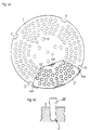
- Figure 1a shows an incubation block (1) in supervision and in Figure 1b one Detail cross section.
- the top of the incubation block essentially has one circular shape.
- the holes (2) in the incubation block and the holes (12) in the holding plate are arranged in four concentric circles.
- the Holding plate (3) has essentially the shape of a segment of a circle and has its underside several stand elements (4a, 4b), which are also used for positioning serve the holding plate on the incubation block.
- the stand elements (4a) have an angled cross section, which in cooperation with the recesses (5) in the incubation block (1) for positioning.
- the holding plate has a standing element (4b) which in a circular recess (6) within the Incubation block (1) engages.
- Figure 1b shows that the shape of the incubation vessel (20) and the bore (2) in the incubation block (1) matched to one another are that the wall of the incubation vessel is close to the inside of the bore (2) is applied to ensure good heat transfer.
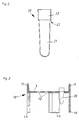
- the incubation vessel shown (20) is in one piece, but can be divided into two sections.
- the section (21) tapers downwards and is closed at the bottom.
- the section (22) which is above the holding plate (3) if the vessel is suspended in the holding plate, has a cylindrical shape and is open to the top.
- the plateau (23) has a width of about 0.3 to 0.6 mm.
- Figure 3 shows a rack (10) in side view with a hooked Incubation vessel (20) and free bores (12). Above the holding plate (3) are the two tabs (11). Below the holding plate (3) are both to recognize the stand elements (4a) and the stand element (4b).
- FIG. 4a shows a system for incubation in a perspective view.
- One rack (10) is placed on the incubation block (1) so that the incubation vessels (20) in the Immerse the holes (2) in the incubation block.
- a light barrier (24) can also be seen in FIG is inside the incubation block. The light barrier detects the Presence of a rack in that a stand element (4b) on the light path interrupts the lower end of the recess (6).
- a cutout is for clarification from this figure shown in side view in Figure 4b. It is in these Figures to recognize that the incubation vessel (20) first in the rack (10) is attached.
- the incubation vessel If the incubation vessel is placed in a hole with the help of the rack (2) of the incubation block (1), the incubation jar bumps into the Bottom of the hole in the incubation block.
- the length of the incubation tube (20) is such that between the plateau (23) and the top of the holding plate (3) A gap is created when the holding plate rests on the incubation block.
- Figure 4b can also be seen that the space between the Bore edge and the incubation tube enlarged when the incubation tube is pushed up out of the holding plate.
Landscapes
- Health & Medical Sciences (AREA)
- Chemical & Material Sciences (AREA)
- Chemical Kinetics & Catalysis (AREA)
- General Health & Medical Sciences (AREA)
- Clinical Laboratory Science (AREA)
- Hematology (AREA)
- Analytical Chemistry (AREA)
- Life Sciences & Earth Sciences (AREA)
- Biochemistry (AREA)
- Molecular Biology (AREA)
- Apparatus Associated With Microorganisms And Enzymes (AREA)
- Automatic Analysis And Handling Materials Therefor (AREA)
- Coating Apparatus (AREA)
- Devices For Use In Laboratory Experiments (AREA)
Description
- einem Rack, bei dem Inkubationsgefäße in Bohrungen einer Halteplatte eingehängt sind,
- einem Inkubationsblock mit Bohrungen zur Aufnahme von Inkubationsgefäßen,
- einer Vorrichtung zur Temperierung des Inkubationsblockes, die thermisch mit dem Inkubationsblock verbunden ist,
- Figur 1a:
- Aufsicht auf einen Inkubationsblock mit eingesetztem Rack
- Figur 1b:
- Teilausschnitt der Figur la in Seitenansicht
- Figur 2:
- Inkubationsgefäß
- Figur 3:
- Rack in seitlicher Darstellung
- Figur 4a:
- Perspektivische Darstellung eines teilweise bestückten Inkubationsblockes
- Figur 4b:
- Schematische Darstellung des Bestückungsvorganges
- (1)
- Inkubationsblock
- (2)
- Bohrungen des Inkubationsblockes
- (3)
- Halteplatte
- (4a, 4b)
- Standelemente
- (5)
- Ausnehmung
- (6)
- kreisförmige Ausnehmung
- (10)
- Rack
- (11)
- Grifflaschen
- (12)
- Bohrungen in Halteplatte
- (20)
- Inkubationsgefäß
- (21)
- unterer Abschnitt Inkubationsgefäß
- (22)
- oberer Abschnitt Inkubationsgefäß
- (23)
- Plateau
- (24)
- Lichtschranke
Claims (9)
- System zur Inkubation von Probeflüssigkeiten, das die folgenden Elemente besitztwobei die Bohrungen in der Halteplatte (12) und die Bohrungen im Inkubationsblock (2) in ihrer geometrischen Anordnung so aufeinander abgestimmt sind, daß sich die Inkubationsgefäße des Racks in die Bohrungen des Inkubationsblockes einpassen, wenn das Rack auf den Inkubationsblock gestellt wird, dadurch gekennzeichnet, daß der Teil der Inkubationsgefäße, der sich unterhalb der Halteplatte befindet, länger ist als die Bohrungen des Inkubationsblockes tief sind, so daß, wenn das Rack auf den Inkubationsblock gestellt wird, sich die Haltevorrichtungen der Inkubationsgefäße von der Halteplatte abheben und sich aufgrund der konischen Verjüngung der Inkubationsgefäße das Spiel in der Ebene der Halteplatte vergrößert, so daß ein Verklemmen verhindert wird.einen Inkubationsblock (1) mit Bohrungen (2) zur Aufnahme von Inkubationsgefäßen,ein Rack (10), bei dem konisch verjüngte Inkubationsgefäße (20) mit Haltevorrichtungen in Bohrungen (12) einer Halteplatte (3) eingehängt sind,eine Vorrichtung zur Temperierung des Inkubationsblockes, die thermisch mit dem Inkubationsblock verbunden ist,
- System gemäß Anspruch 1, bei dem die Bohrungen im Inkubationsblock und die Außenwandungen der Inkubationsgefäße so aufeinander abgestimmt sind, daß die Außenwandung des Inkubationsgefäßes an der Innenwandung der Bohrung des Inkubationsblockes eng anliegt.
- System gemäß Anspruch 1, wobei an der Unterseite der Halteplatte Standelemente (4a, 4b) angebracht sind und sich im Inkubationsblock Ausnehmungen zur Aufnahme dieser Standelemente befinden.
- System gemäß Anspruch 1, bei dem sich auf der Oberseite der Halteplatte ein oder mehrere Grifflaschen (11) befinden.
- System gemäß Anspruch 1 oder 3 mit einem Sensor innerhalb des Inkubationsblockes, welcher die Anwesenheit eines Racks detektiert.
- System gemäß Anspruch 1, bei dem die Halteplatte die Form eines Kreissegmentes oder eines Teiles eines Kreisringes besitzt.
- Verfahren zur Inkubation von Probeflüssigkeiten miteinem Inkubationsblock (1) mit Bohrungen zur Aufnahme von Inkubationsgefäßen,einem Rack (10), bei dem konisch verjüngte Inkubationsgefäße (20) mit Haltevorrichtungen in Bohrungen (12) einer Halteplatte (3) eingehängt sind und der Teil der Inkubationsgefäße, der sich unterhalb der Halteplatte befindet länger ist als die Bohrungen des Inkubationsblockes tief sind, sowieeiner Vorrichtung zur Temperierung des Inkubationsblockes, die thermisch mit dem Inkubationsblock verbunden ist,
wobei die Bohrungen in der Halteplatte (12) und die Bohrungen im Inkubationsblock (2) in ihrer geometrischen Anordnung so aufeinander abgestimmt sind, daß sich die Inkubationsgefäße des Racks in die Bohrungen des Inkubationsblockes einpassen, wenn das Rack auf den Inkubationsblock gestellt wird, mit den SchrittenEinstellen des Racks in den Inkubationsblock, wobei sich die Haltevorrichtungen der Inkubationsgefäße von der Halteplatte abheben und sich aufgrund der konischen Verjüngung der Inkubationsgefäße das Spiel in der Ebene der Halteplatte vergrößert,Temperierung der Inkubationsgefäße. - Verfahren gemäß Anspruch 7, bei dem das Rack (10) vom Benutzer manuell mit Inkubationsgefäßen (20) bestückt wird.
- Verfahren gemäß Anspruch 7, bei dem die Bestückung des Racks (10) mit Inkubationsgefäßen (20) automatisch erfolgt und das bestückte Rack dem Benutzer zur Verfügung gestellt wird.
Applications Claiming Priority (2)
| Application Number | Priority Date | Filing Date | Title |
|---|---|---|---|
| DE4440294A DE4440294A1 (de) | 1994-11-11 | 1994-11-11 | System zur Inkubation von Probeflüssigkeiten |
| DE4440294 | 1994-11-11 |
Publications (2)
| Publication Number | Publication Date |
|---|---|
| EP0711603A1 EP0711603A1 (de) | 1996-05-15 |
| EP0711603B1 true EP0711603B1 (de) | 2001-08-16 |
Family
ID=6533054
Family Applications (1)
| Application Number | Title | Priority Date | Filing Date |
|---|---|---|---|
| EP95117563A Expired - Lifetime EP0711603B1 (de) | 1994-11-11 | 1995-11-08 | System zur Inkubation von Probeflüssigkeiten |
Country Status (5)
| Country | Link |
|---|---|
| US (1) | US5670120A (de) |
| EP (1) | EP0711603B1 (de) |
| JP (1) | JPH08228756A (de) |
| DE (2) | DE4440294A1 (de) |
| ES (1) | ES2162886T3 (de) |
Families Citing this family (33)
| Publication number | Priority date | Publication date | Assignee | Title |
|---|---|---|---|---|
| DE29623597U1 (de) * | 1996-11-08 | 1999-01-07 | Eppendorf - Netheler - Hinz Gmbh, 22339 Hamburg | Temperierblock mit Temperiereinrichtungen |
| WO1999009137A1 (en) * | 1997-08-20 | 1999-02-25 | Biopore, Inc. | Cassette device and system to facilitate cryopreservation |
| US6132684A (en) * | 1997-10-31 | 2000-10-17 | Becton Dickinson And Company | Sample tube holder |
| US8337753B2 (en) | 1998-05-01 | 2012-12-25 | Gen-Probe Incorporated | Temperature-controlled incubator having a receptacle mixing mechanism |
| ES2322859T3 (es) | 1998-05-01 | 2009-06-30 | Gen-Probe Incorporated | Analizador de diagnostico automatizado. |
| US6117391A (en) * | 1998-06-18 | 2000-09-12 | Bayer Corporation | Cup handling subsystem for an automated clinical chemistry analyzer system |
| EP1000661A1 (de) * | 1998-10-29 | 2000-05-17 | Hans-Knöll-Institut für Naturstoff-Forschung e.v. | Ultradünnwandige Mehrfachlochplatte für Heizblock-Thermozyklen |
| DE19926937A1 (de) * | 1999-06-14 | 2001-01-04 | Biopsytec Gmbh | Vorrichtung zur Aufnahme von Labor Reaktionsgefäßen |
| US6425438B1 (en) | 2000-06-13 | 2002-07-30 | Dan-Kar Corporation | Method for defrosting a container and a frozen liquid therein |
| US6825041B2 (en) | 2001-03-16 | 2004-11-30 | Beckman Coulter, Inc. | Method and system for automated immunochemistry analysis |
| GB0110449D0 (en) * | 2001-04-28 | 2001-06-20 | Genevac Ltd | Improvements in and relating to the heating of microtitre well plates in centrifugal evaporators |
| US7250303B2 (en) | 2001-07-20 | 2007-07-31 | Ortho-Clinical Diagnostics, Inc. | Chemistry system for a clinical analyzer |
| US7459302B2 (en) | 2001-10-02 | 2008-12-02 | Stratagene California | Side-wall heater for thermocycler device |
| WO2003057819A1 (en) * | 2002-01-07 | 2003-07-17 | Uab Research Foundation | Electroporation cuvette-pipette tips, multi-well cuvette arrays, and electrode template apparatus adapted for automation and uses thereof |
| DE10243209A1 (de) * | 2002-03-22 | 2003-10-02 | Endress & Hauser Wetzer Gmbh | Vorrichtung zur Kühlung eines Probennehmers |
| GB0229410D0 (en) * | 2002-12-17 | 2003-01-22 | Molecular Sensing Plc | Sample vessel |
| CA2842402C (en) | 2005-03-10 | 2016-02-23 | Gen-Probe Incorporated | Systems and methods to perform assays for detecting or quantifying analytes within samples |
| DE102006062714B4 (de) | 2006-03-09 | 2013-02-21 | Eppendorf Ag | Vorrichtung zum Mischen von Laborgefäß-Inhalten |
| KR100911627B1 (ko) * | 2007-07-10 | 2009-08-12 | 서강대학교산학협력단 | 고속 시료 샘플링 장치 |
| US20110294208A1 (en) * | 2009-02-11 | 2011-12-01 | Nancy Allbritton | Method and device for cell selection and collection in an isolated culturing environment |
| US9046507B2 (en) | 2010-07-29 | 2015-06-02 | Gen-Probe Incorporated | Method, system and apparatus for incorporating capacitive proximity sensing in an automated fluid transfer procedure |
| US8592695B2 (en) * | 2010-11-30 | 2013-11-26 | Jose Maria Las Navas Garcia | Stackable crucible, a system using a stackable crucible, and a method of using a stackable crucible |
| AU2012222178B2 (en) | 2011-02-24 | 2014-12-18 | Gen-Probe Incorporated | Systems and methods for distinguishing optical signals of different modulation frequencies in an optical signal detector |
| BR112014032911A2 (pt) | 2012-06-28 | 2017-06-27 | Fluoresentric Inc | dispositivo indicador químico |
| CN107831324B (zh) | 2013-03-15 | 2021-11-19 | 雅培制药有限公司 | 具有后面可进入轨道系统的自动化诊断分析仪及相关方法 |
| JP6165961B2 (ja) | 2013-03-15 | 2017-07-19 | アボット・ラボラトリーズAbbott Laboratories | 前処理カルーセルを有する診断分析装置および関連方法 |
| ES3037815T3 (en) | 2013-03-15 | 2025-10-07 | Abbott Lab | Automated diagnostic analyzers having vertically arranged carousels and related methods |
| GB2591198B (en) | 2014-04-04 | 2021-10-27 | It Is Int Ltd | Biochemical reaction system |
| WO2016018910A1 (en) * | 2014-07-28 | 2016-02-04 | Douglas Scientific, LLC | Instrument for analyzing biological samples and reagents |
| EP3349903A4 (de) * | 2015-09-16 | 2019-03-13 | Fluoresentric, Inc. | Vorrichtung, systeme und verfahren zur dynamischen flussverstärkung von proben |
| JP7316027B2 (ja) * | 2018-05-24 | 2023-07-27 | 三菱重工業株式会社 | 回転軸系の捩れ振動計測装置 |
| CN110205241A (zh) * | 2019-04-23 | 2019-09-06 | 扬州市海诚生物技术有限公司 | 一种杀菌效果好且便于夹持试管的生化培养箱 |
| US12478969B2 (en) * | 2022-09-29 | 2025-11-25 | Seegene, Inc. | Device for heating sample |
Family Cites Families (21)
| Publication number | Priority date | Publication date | Assignee | Title |
|---|---|---|---|---|
| US3260413A (en) * | 1964-08-31 | 1966-07-12 | Scientific Industries | Automatic chemical analyzer |
| US3847200A (en) * | 1972-05-01 | 1974-11-12 | Brinkmann Instr Inc | Apparatus for concentrating laboratory specimens by evaporation |
| US3964867A (en) * | 1975-02-25 | 1976-06-22 | Hycel, Inc. | Reaction container |
| US4310488A (en) * | 1980-05-19 | 1982-01-12 | Hoffmann-La Roche Inc. | Sample or reagent container for analyzers |
| US4335620A (en) | 1980-07-16 | 1982-06-22 | The Upjohn Company | Temperature controlled sample carrier |
| EP0087028B1 (de) | 1982-02-13 | 1986-08-27 | Kabushiki Kaisha Toshiba | Einrichtung zur automatischen chemischen Analyse |
| CA1220053A (en) | 1983-10-01 | 1987-04-07 | Toyo Soda Manufacturing Co., Ltd. | Method for chromatographic analysis and apparatus therefor |
| DE3405293A1 (de) | 1984-02-15 | 1985-09-05 | Eppendorf Gerätebau Netheler + Hinz GmbH, 2000 Hamburg | Verfahren zum temperieren einer zu analysierenden probenfluessigkeit sowie von reagenzien zur durchfuehrung von analysen sowie vorrichtung zur durchfuehrung des verfahrens |
| FI853895A0 (fi) * | 1985-10-07 | 1985-10-07 | Labsystems Oy | Immunologiskt bestaemningssystem. |
| US4933146A (en) | 1986-07-11 | 1990-06-12 | Beckman Instruments, Inc. | Temperature control apparatus for automated clinical analyzer |
| DE8804938U1 (de) * | 1988-04-14 | 1988-05-26 | Deutsche Metrohm GmbH & Co, 7024 Filderstadt | Vorrichtung zur chemischen Untersuchung und/oder Behandlung von in mehreren Probengefäßen enthaltenen Substanzen |
| US4865986A (en) | 1988-10-06 | 1989-09-12 | Coy Corporation | Temperature control apparatus |
| FR2638529A1 (fr) * | 1988-10-28 | 1990-05-04 | Biosema | Segment reactionnel a prepositionnement pour analyseur automatique d'echantillons par colorimetrie |
| US4950608A (en) * | 1989-04-25 | 1990-08-21 | Scinics Co., Ltd. | Temperature regulating container |
| JP2513912Y2 (ja) * | 1990-03-13 | 1996-10-09 | 株式会社堀場製作所 | 分析装置等における試料容器の冷却装置 |
| US5282543A (en) * | 1990-11-29 | 1994-02-01 | The Perkin Elmer Corporation | Cover for array of reaction tubes |
| KR100236506B1 (ko) * | 1990-11-29 | 2000-01-15 | 퍼킨-엘머시터스인스트루먼츠 | 폴리머라제 연쇄 반응 수행 장치 |
| CA2069530A1 (en) * | 1991-06-03 | 1992-12-04 | Cass J. Grandone | Reagent pack for immunoassays |
| ES2208638T3 (es) * | 1992-03-27 | 2004-06-16 | Abbott Laboratories | Sistema de analisis automatizado de acceso continuo y aleatorio y componentes para un sistea de este tipo. |
| US5271896A (en) * | 1993-04-16 | 1993-12-21 | Eastman Kodak Company | Plunger and driver mechanism for an analyzer |
| CA2130517C (en) * | 1993-09-10 | 1999-10-05 | Walter Fassbind | Array of reaction containers for an apparatus for automatic performance of temperature cycles |
-
1994
- 1994-11-11 DE DE4440294A patent/DE4440294A1/de not_active Withdrawn
-
1995
- 1995-11-08 ES ES95117563T patent/ES2162886T3/es not_active Expired - Lifetime
- 1995-11-08 JP JP7290060A patent/JPH08228756A/ja active Pending
- 1995-11-08 EP EP95117563A patent/EP0711603B1/de not_active Expired - Lifetime
- 1995-11-08 DE DE59509510T patent/DE59509510D1/de not_active Expired - Fee Related
- 1995-11-09 US US08/555,428 patent/US5670120A/en not_active Expired - Fee Related
Also Published As
| Publication number | Publication date |
|---|---|
| JPH08228756A (ja) | 1996-09-10 |
| US5670120A (en) | 1997-09-23 |
| ES2162886T3 (es) | 2002-01-16 |
| EP0711603A1 (de) | 1996-05-15 |
| DE4440294A1 (de) | 1996-05-15 |
| DE59509510D1 (de) | 2001-09-20 |
Similar Documents
| Publication | Publication Date | Title |
|---|---|---|
| EP0711603A1 (de) | System zur Inkubation von Probeflüssigkeiten | |
| DE69617280T2 (de) | Vorrichtung zur Durchführung von Reaktionen mittels thermischen Zyklen und Reaktor hierfür | |
| DE69612973T2 (de) | Verbesserung an der behandlung von proben | |
| EP0642828B1 (de) | Reaktionsbehälteranordnung für eine Vorrichtung zur automatischen Durchführung von Temperaturzyklen | |
| DE69129325T2 (de) | Zweiteilige Haltevorrichtung aus Kunststoff für mit Abdeckkappe versehene Probenröhrchen | |
| EP1081233B1 (de) | Probenkammer zur Flüssigkeitsbehandlung biologischer Proben | |
| DE69333785T2 (de) | Anordnung zum Aufbau eines Proben- und Reagenzien-Aufnahmesystems für in situ PCR auf einer Lamelle | |
| EP0676643B1 (de) | System zur kontaminationsfreien Bearbeitung von Reaktionsabläufen | |
| EP0539369B1 (de) | Platte mit einer mehrzahl von mulden zur aufnahme von chemischen und/oder biochemischen und/oder mikrobiologischen substanzen | |
| DE60018386T2 (de) | Station zur nukleinsäurevervielfältigung für wegwerftestträger | |
| DE69429159T2 (de) | Verfahren für einen spezifischen Bindungstest mit magnetischen Teilchen | |
| DE69706313T2 (de) | Verfahren und vorrichtung, reagenzien zu transferieren und zu kombinieren | |
| EP2030683B1 (de) | Vorrichtung und Verfahren zur Entnahme von Substanzen aus vorgefüllten Behältnissen | |
| DE69412632T2 (de) | Vorrichtung und verfahren zur überführung einer probe eines fluids | |
| EP0444144B1 (de) | Thermostatisiergerät | |
| WO2002030774A1 (de) | Verschlusselement und verschlusssystem | |
| DE102008025992B4 (de) | Titerplatte und Verfahren zur Detektion eines Analyten | |
| DE69827567T2 (de) | Entnahmegefäß-Anordnung | |
| EP0642831A1 (de) | Vorrichtung zur automatischen Durchführung von Temperaturzyklen | |
| DE3539136A1 (de) | Analytische elektroelutionsvorrichtung | |
| EP3162443A1 (de) | Nadelführung mit zentrierung für septum-piercing | |
| DE112017004226T5 (de) | Kompakte Thermozyklusvorrichtungund System umfassend die Thermozyklusvorrichtung | |
| DE69413643T2 (de) | Probentraeger | |
| EP3130926B1 (de) | Verfahren zur bereitstellung eines reaktionsansatzes und automatisches analysegerät | |
| DE4409436A1 (de) | Verfahren zur Bearbeitung von Nukleinsäuren |
Legal Events
| Date | Code | Title | Description |
|---|---|---|---|
| PUAI | Public reference made under article 153(3) epc to a published international application that has entered the european phase |
Free format text: ORIGINAL CODE: 0009012 |
|
| AK | Designated contracting states |
Kind code of ref document: A1 Designated state(s): CH DE ES FR GB IT LI |
|
| 17P | Request for examination filed |
Effective date: 19961115 |
|
| RAP3 | Party data changed (applicant data changed or rights of an application transferred) |
Owner name: ROCHE DIAGNOSTICS GMBH |
|
| 17Q | First examination report despatched |
Effective date: 19991105 |
|
| GRAG | Despatch of communication of intention to grant |
Free format text: ORIGINAL CODE: EPIDOS AGRA |
|
| GRAG | Despatch of communication of intention to grant |
Free format text: ORIGINAL CODE: EPIDOS AGRA |
|
| GRAH | Despatch of communication of intention to grant a patent |
Free format text: ORIGINAL CODE: EPIDOS IGRA |
|
| GRAH | Despatch of communication of intention to grant a patent |
Free format text: ORIGINAL CODE: EPIDOS IGRA |
|
| GRAA | (expected) grant |
Free format text: ORIGINAL CODE: 0009210 |
|
| AK | Designated contracting states |
Kind code of ref document: B1 Designated state(s): CH DE ES FR GB IT LI |
|
| PG25 | Lapsed in a contracting state [announced via postgrant information from national office to epo] |
Ref country code: GB Free format text: LAPSE BECAUSE OF FAILURE TO SUBMIT A TRANSLATION OF THE DESCRIPTION OR TO PAY THE FEE WITHIN THE PRESCRIBED TIME-LIMIT Effective date: 20010816 |
|
| REG | Reference to a national code |
Ref country code: CH Ref legal event code: EP |
|
| REF | Corresponds to: |
Ref document number: 59509510 Country of ref document: DE Date of ref document: 20010920 |
|
| PG25 | Lapsed in a contracting state [announced via postgrant information from national office to epo] |
Ref country code: LI Free format text: LAPSE BECAUSE OF NON-PAYMENT OF DUE FEES Effective date: 20011130 Ref country code: CH Free format text: LAPSE BECAUSE OF NON-PAYMENT OF DUE FEES Effective date: 20011130 |
|
| ET | Fr: translation filed | ||
| REG | Reference to a national code |
Ref country code: ES Ref legal event code: FG2A Ref document number: 2162886 Country of ref document: ES Kind code of ref document: T3 |
|
| GBV | Gb: ep patent (uk) treated as always having been void in accordance with gb section 77(7)/1977 [no translation filed] |
Effective date: 20010816 |
|
| PLBE | No opposition filed within time limit |
Free format text: ORIGINAL CODE: 0009261 |
|
| STAA | Information on the status of an ep patent application or granted ep patent |
Free format text: STATUS: NO OPPOSITION FILED WITHIN TIME LIMIT |
|
| REG | Reference to a national code |
Ref country code: CH Ref legal event code: PL |
|
| 26N | No opposition filed | ||
| PGFP | Annual fee paid to national office [announced via postgrant information from national office to epo] |
Ref country code: ES Payment date: 20071119 Year of fee payment: 13 Ref country code: DE Payment date: 20071130 Year of fee payment: 13 |
|
| PGFP | Annual fee paid to national office [announced via postgrant information from national office to epo] |
Ref country code: IT Payment date: 20071120 Year of fee payment: 13 |
|
| PGFP | Annual fee paid to national office [announced via postgrant information from national office to epo] |
Ref country code: FR Payment date: 20071105 Year of fee payment: 13 |
|
| PG25 | Lapsed in a contracting state [announced via postgrant information from national office to epo] |
Ref country code: IT Free format text: LAPSE BECAUSE OF NON-PAYMENT OF DUE FEES Effective date: 20081108 |
|
| REG | Reference to a national code |
Ref country code: FR Ref legal event code: ST Effective date: 20090731 |
|
| PG25 | Lapsed in a contracting state [announced via postgrant information from national office to epo] |
Ref country code: DE Free format text: LAPSE BECAUSE OF NON-PAYMENT OF DUE FEES Effective date: 20090603 |
|
| REG | Reference to a national code |
Ref country code: ES Ref legal event code: FD2A Effective date: 20081110 |
|
| PG25 | Lapsed in a contracting state [announced via postgrant information from national office to epo] |
Ref country code: ES Free format text: LAPSE BECAUSE OF NON-PAYMENT OF DUE FEES Effective date: 20081110 |
|
| PG25 | Lapsed in a contracting state [announced via postgrant information from national office to epo] |
Ref country code: FR Free format text: LAPSE BECAUSE OF NON-PAYMENT OF DUE FEES Effective date: 20081130 |