EP0710922B1 - A document processing and data distribution system - Google Patents
A document processing and data distribution system Download PDFInfo
- Publication number
- EP0710922B1 EP0710922B1 EP95307789A EP95307789A EP0710922B1 EP 0710922 B1 EP0710922 B1 EP 0710922B1 EP 95307789 A EP95307789 A EP 95307789A EP 95307789 A EP95307789 A EP 95307789A EP 0710922 B1 EP0710922 B1 EP 0710922B1
- Authority
- EP
- European Patent Office
- Prior art keywords
- processing means
- activities
- portable medium
- flight
- data items
- Prior art date
- Legal status (The legal status is an assumption and is not a legal conclusion. Google has not performed a legal analysis and makes no representation as to the accuracy of the status listed.)
- Expired - Lifetime
Links
Images


Classifications
-
- G—PHYSICS
- G06—COMPUTING OR CALCULATING; COUNTING
- G06K—GRAPHICAL DATA READING; PRESENTATION OF DATA; RECORD CARRIERS; HANDLING RECORD CARRIERS
- G06K17/00—Methods or arrangements for effecting co-operative working between equipments covered by two or more of main groups G06K1/00 - G06K15/00, e.g. automatic card files incorporating conveying and reading operations
Definitions
- This invention relates to a document processing and data distribution system, and in particular to one in which a user manipulates documents relating to activities, such that the manipulations give rise to the distribution of updated information to an electronically stored database and/or to other users.
- the invention is particularly, but not exclusively, suited to air traffic control (ATC) environments.
- ATC air traffic control
- An ATC workstation commonly includes a terminal on the controller's desk to access a database, and a rack mounted on the wall above the terminal on which strips of paper or card, one strip for each flight, are placed, removed, annotated, moved around, etc.
- ATC workstation commonly includes a terminal on the controller's desk to access a database, and a rack mounted on the wall above the terminal on which strips of paper or card, one strip for each flight, are placed, removed, annotated, moved around, etc.
- the present invention provides an information processing system, comprising: means for storing a database of data items relating to activities, a number of said data items being represented on a respective portion of a portable medium corresponding to one of said activities, processing means, coupled to the storing means, for updating one or more of said data items in response to a user operation, a plurality of workstations, each workstation comprising means for removably mounting said portable media in an array, a camera and a projector focussed on the array, each camera and projector being coupled to the processing means, wherein said user operations include marking a sign on a portable medium, and wherein said processing means includes means for recognising said sign.
- a video camera is located above each controller's (rack of) flight strips to act as an input device for the flight progress computers, and a video projector, adjacent the camera overlays information generated by the computer on top of the flight strips.
- a controller annotates a paper strip with a pen
- the annotation(s) is (are) captured by the camera, extracted from the image and processed by the flight progress computer.
- the results of this processing can be fed to other computer-based tools.
- the results of the raw annotations can be displayed on other controllers' flight strips by dedicated computer-controlled image projectors.
- An advantage is that the invention augments the conventional ATC arrangement, preserving the benefits of paper-based 'direct interaction', while providing the enhancement of integrated information systems.
- the solution is ideal in that it does not require the replacement of paper flight progress strips, but integrates the paper strips with the electronic flight progress computers, allowing annotations by pen to be captured, processed and propagated as necessary.
- FIG. 1 shows a simplified diagram of a conventional ATC suite (at Pole Hill): it is a simplified representation and is not to scale.
- Designator Strips are all the same size (the size of a flight strip) and the width of the strip rack 'bays' is uniform.
- the map (Fig. 1(b)) shows how Designator Strip positions correspond to geographical locations of the reporting points they represent.
- the ATC suite typically includes static map displays 102, an early warning radar (showing all LATCC airspace), live strip racks 106, and radar displays 108, 110 (in this case for the Irish Sea and Pole Hill sectors, respectively).
- the ATC suite includes chinographs 112 with weather information, pigeon holes 114 for 'hour blocks' of dead flight strips and empty strip holders 116.
- a computer terminal 118 gives the ATC controller access to the database, and enables the controller to print out strips on the connected printer 120.
- Fig.2 this shows examples of live flight strips printed for a single aircraft (they are not based on actual flight strips but are included as examples of strip arrangement).
- Strips 1 ⁇ and 2 ⁇ are for the Ottringham and Pole Hill reporting points, respectively, and would be placed in front of the Pole Hill sector controller (see Fig. 1).
- Strip 3 ⁇ is for the Isle of Man reporting point and would be placed in front of the Irish Sea sector controller.
- Each flight strip 4 is preferably of a standard format, and has a number of sections or portions 202, each section 202 having a predetermined purpose, i.e. as a location for a printed data item and/or as a place in which controllers can make annotations.
- the data items printed on the strip typically include the arrival time 204 at the reporting point, the identifier 206 of the reporting point the strip is for, the call sign 208, the squawk indent 210, route information 212 and the last reporting point and time 214.
- Section 216 provides a scribble box for controllers in which to make annotations.
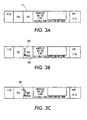
- Figure 3 illustrates typical controller annotations of flight strips.
- a "clean" strip is shown.
- Figs 3(b) and (c) show respectively a strip marked by hand by a controller with signs 302 and 304 to indicate a requested action in relation to the flight, and a strip marked by hand by a controller with sign 306 to indicate a completed action.
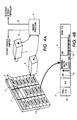
- FIG. 4 this is a schematic illustration of (a) the arrangement of flight strip rack, camera and projector at each controller's workstation, and (b) an electronically augmented flight progress strip.
- the rack 2 is mounted above the controller's VDU terminal(s) (displaying radar data such as current aircraft position; not shown), and supports paper flight strips 4 which in this case are arranged in three columns.
- a camera 6 and a video projector 8 are focussed on the array of flight strips 4, and both are connected to image processing hardware 9.
- a similar camera and videoprojector arrangement is known from EP-A-495622.
- a controller sits in front of the rack 2 and is able to talk to the pilots of the aircraft and other controllers using a radio/telephone.
- the image processing hardware 9 carries out the image processing techniques as described below.
- annotation data giving information on the future state of the airspace can be added to data from other sources, such as radar processing, to allow development of systems such as conflict detection and collision alert.
- annotations can be propagated to other controllers' displays (VDU or video projectors) and superimposed on appropriate flight strips.
- Fig. 4(b) an electronically augmented flight progress strip is shown: the strip has pre-printed information 14, hand-drawn annotations 16, and annotations 18 super-imposed by the projector 8.
- the hand-drawn annotation 16 may be in different colours (corresponding to controllers at different levels of responsibility in the ATC room), and the image processing system may incorporate simple techniques for distinguishing between the markings of different colours, i.e. so that the marks of a supervisory controller take priority over those of a lower level controller.
- the hand-drawn annotations 16 are captured by the camera, processed where necessary by performing handwriting recognition techniques which are known in the art; and then this information is propagated to the workstation of selected other ATC controllers.
- the video projector 8 at each of the selected workstations is commanded by the processing system 9 to display the information (which in the case of characters and numerals has preferably been converted into an appropriate font) in a suitable section of the corresponding flight strip 4.
- the marking 18 has been made by a controller at a remote workstation, and has been processed and displayed by the video projector 8 at the current workstation in the appropriate section 17 of the strip 4.
- FIG. 5(a) this is a flow chart of the data processing operations relating to radar data and flight information
- Figs 5(b)-(d) are flow charts of the image processing employed when a controller carries out manipulations on a flight strip.
- ATC controllers mark flight strips when decisions are made relating to a flight. These decisions affect the path of the aircraft, and hence the work of other controllers. These changes (decisions) are manually relayed between controllers, but are not entered into the integrated radar data and flight plan processing systems.
- the information processing systems will have more detailed and accurate data reflecting both (a) radar data and flight plan data, and (b) controlling data.
- step S1 The data processing operations relating to radar data and flight information are shown in Fig. 5 (a).
- step S1 the system waits (step S1) for receipt of new target information (e.g. relating to an incoming flight).
- step S2 the information is used in step S2 to update the screen displays of appropriate controllers and as updated information to be logged into the history store (not shown)of the data processing system.
- step S3 a check is made for any conflicts with currently processed flights, and if there is none the system returns to waiting for new target information (at step S1). In the event of a conflict being found, the data from the the strip information database is read and checked at step S4. At step S5 a further analysis is made to establish whether there is still a conflict with any currently processed flight. If there is none, the system returns to waiting for new target information (at step S1).
- step S6 the system checks (step S6) whether the alert system is on, and if it is not, then the alert system is switched on at step S7. If the alert system is already on, it is switched (step s8) to a more imperative stage in the warning procedure.
- step S10 the system captures an image of the flight strips 4 in the controller's rack 2. A check is then made to find if the is any change from when the image of the strips was last grabbed, and if there is no change, the processing returns (after a predetermined time which may be set in a conventional way beforehand) to grab a new image of the strips.
- step S12 the difference (e.g. on a pixel-by-pixel basis) is extracted at step S12.
- This step preferably includes the discarding of spurious artifacts in the image, as is known in the art (e.g. Jähne B., Digital Image Processing, Ch. 6, Springer-Verlag, Heidelberg, 1991), and handwriting or optical character recognition techniques, which are known in the art.
- the information which has been added e.g. a controller's annotation
- Fig. 5(c) illustrates the substeps of step S14 in Fig. 5(b). Initially, the system waits (step S142) for the new image data. Then, the new image data is combined at step 144 with images from the cameras at other controllers' workstations. Finally, the projected image is changed at step 146.
- Fig. 5(c) illustrates the substeps of step S15 in Fig. 5(b).
- the system waits (step S152) for information from the strip camera processing. Once this information has been received, an OCR/pattern matching operation is performed on the information at step S154. Thereafter, the processed information is added (step S156) to the strip information database stored in memory.
- the rack 2 may be adapted to support the strips not only in a position where the strips are flat with their planes parallel to the plane of the rack, but in one or more alternative positions, for example 'cocked' out of position to indicate potential control problems.
- This processing technique may be incorporated into step S12 of Fig. 5(b).
- each holder in the rack 2 may be capable of supporting a strip 4 so that it is tilted away from the plane of the rack (see Fig. 4(a) with the top edge of the strip spaced apart from the plane of the rack; and the strip may thereby make an angle of 30-50 degrees with the plane of the rack. When in such a position, the strip unveils a portion 5 (see Fig.
- the planar surface 3 may be of a colour or gray level which provides sufficient contrast with respect to the material of the flight strips for the image processing to determine that the portion 5 is exposed and therefore that the strip 4 is tilted out of the normal position.
- Such a technique means that the potential control problem is both immediately visible to the local controller and the fact that it exists is readily distributable to other controllers who need to be aware of it.
Landscapes
- Physics & Mathematics (AREA)
- General Physics & Mathematics (AREA)
- Engineering & Computer Science (AREA)
- Theoretical Computer Science (AREA)
- Traffic Control Systems (AREA)
Applications Claiming Priority (2)
| Application Number | Priority Date | Filing Date | Title |
|---|---|---|---|
| GB9422012A GB9422012D0 (en) | 1994-11-01 | 1994-11-01 | Document processing and data distribution system |
| GB9422012 | 1994-11-01 |
Publications (3)
| Publication Number | Publication Date |
|---|---|
| EP0710922A2 EP0710922A2 (en) | 1996-05-08 |
| EP0710922A3 EP0710922A3 (Direct) | 1996-05-29 |
| EP0710922B1 true EP0710922B1 (en) | 2000-07-12 |
Family
ID=10763714
Family Applications (1)
| Application Number | Title | Priority Date | Filing Date |
|---|---|---|---|
| EP95307789A Expired - Lifetime EP0710922B1 (en) | 1994-11-01 | 1995-11-01 | A document processing and data distribution system |
Country Status (5)
| Country | Link |
|---|---|
| US (1) | US5764508A (Direct) |
| EP (1) | EP0710922B1 (Direct) |
| JP (1) | JP3688363B2 (Direct) |
| DE (1) | DE69517916T2 (Direct) |
| GB (1) | GB9422012D0 (Direct) |
Families Citing this family (10)
| Publication number | Priority date | Publication date | Assignee | Title |
|---|---|---|---|---|
| US8432414B2 (en) * | 1997-09-05 | 2013-04-30 | Ecole Polytechnique Federale De Lausanne | Automated annotation of a view |
| US20040217228A1 (en) * | 2002-03-14 | 2004-11-04 | Dimensions International Inc. | Data transfer system |
| US7099341B2 (en) * | 2002-05-03 | 2006-08-29 | International Business Machines Corporation | Traffic routing management system using the open shortest path first algorithm |
| IL153783A (en) * | 2003-01-02 | 2009-05-04 | Amichai Ben Ari | Method for projecting signs on printed matter and means for the same |
| JP2013070218A (ja) * | 2011-09-22 | 2013-04-18 | Sharp Corp | 投影装置 |
| US8874288B1 (en) | 2013-06-20 | 2014-10-28 | Raytheon Company | Adding weather icon to electronic flight strips |
| US10810892B2 (en) | 2017-02-01 | 2020-10-20 | Honeywell International Inc. | Air traffic control flight management |
| US10037705B1 (en) * | 2017-02-01 | 2018-07-31 | Honeywell International Inc. | Air traffic control flight management |
| US11262900B1 (en) * | 2018-07-30 | 2022-03-01 | The Boeing Company | Graphical user interface in a computer system in an aircraft |
| JP7768104B2 (ja) * | 2022-11-25 | 2025-11-12 | 日本電気株式会社 | フライトストリップ処理システム、フライトストリップ処理方法、処理装置、電子ストリップ端末、プログラム |
Family Cites Families (18)
| Publication number | Priority date | Publication date | Assignee | Title |
|---|---|---|---|---|
| US4205780A (en) * | 1977-03-21 | 1980-06-03 | Teknekron, Inc. | Document processing system and method |
| US4468694A (en) * | 1980-12-30 | 1984-08-28 | International Business Machines Corporation | Apparatus and method for remote displaying and sensing of information using shadow parallax |
| US4642775A (en) * | 1984-05-25 | 1987-02-10 | Sundstrand Data Control, Inc. | Airborne flight planning and information system |
| JPS61273779A (ja) * | 1985-05-28 | 1986-12-04 | Canon Inc | 情報再生装置 |
| JPS6339777U (Direct) * | 1986-08-29 | 1988-03-15 | ||
| US4827419A (en) * | 1986-09-22 | 1989-05-02 | Lasertrak Corporation | Portable navigational planning device |
| US5200901A (en) * | 1986-11-18 | 1993-04-06 | Ufa, Inc. | Direct entry air traffic control system for accident analysis and training |
| US4975696A (en) * | 1987-03-23 | 1990-12-04 | Asinc, Inc. | Real-time flight and destination display for aircraft passengers |
| US5032841A (en) * | 1987-11-30 | 1991-07-16 | Radar Data Systems, Inc. | Method and apparatus for ground radar information display system |
| US5108889A (en) * | 1988-10-12 | 1992-04-28 | Thorne, Smith, Astill Technologies, Inc. | Assay for determining analyte using mercury release followed by detection via interaction with aluminum |
| EP0424803B1 (de) * | 1989-10-24 | 1997-07-16 | FROESSL, Horst | Verfahren zur mindestens teilweisen Umsetzung von Bilddaten in Text mit Vorbereitung für nachfolgende Speicherung oder Weiterverarbeitung |
| JPH07115677B2 (ja) * | 1990-10-30 | 1995-12-13 | 嘉三 藤本 | 航空機の飛行情報記録方法とその装置 |
| GB9100733D0 (en) * | 1991-01-14 | 1991-02-27 | Xerox Corp | Indexing of data sets |
| US5208590A (en) * | 1991-09-20 | 1993-05-04 | Asinc, Inc. | Flight phase information display system for aircraft passengers |
| EP0622722B1 (en) * | 1993-04-30 | 2002-07-17 | Xerox Corporation | Interactive copying system |
| JP3181446B2 (ja) * | 1993-09-24 | 2001-07-03 | 株式会社東芝 | 情報記憶装置 |
| JP3175463B2 (ja) * | 1994-02-24 | 2001-06-11 | 三菱電機株式会社 | レーザ切断方法 |
| US5659475A (en) * | 1994-03-17 | 1997-08-19 | Brown; Daniel M. | Electronic air traffic control system for use in airport towers |
-
1994
- 1994-11-01 GB GB9422012A patent/GB9422012D0/en active Pending
-
1995
- 1995-10-31 US US08/551,295 patent/US5764508A/en not_active Expired - Lifetime
- 1995-11-01 JP JP28471795A patent/JP3688363B2/ja not_active Expired - Fee Related
- 1995-11-01 EP EP95307789A patent/EP0710922B1/en not_active Expired - Lifetime
- 1995-11-01 DE DE69517916T patent/DE69517916T2/de not_active Expired - Lifetime
Also Published As
| Publication number | Publication date |
|---|---|
| US5764508A (en) | 1998-06-09 |
| GB9422012D0 (en) | 1994-12-21 |
| JP3688363B2 (ja) | 2005-08-24 |
| JPH08255300A (ja) | 1996-10-01 |
| DE69517916T2 (de) | 2000-11-09 |
| DE69517916D1 (de) | 2000-08-17 |
| EP0710922A3 (Direct) | 1996-05-29 |
| EP0710922A2 (en) | 1996-05-08 |
Similar Documents
| Publication | Publication Date | Title |
|---|---|---|
| US5459826A (en) | System and method for preparing text and pictorial materials for printing using predetermined coding and merging regimen | |
| JP5963325B2 (ja) | マーカに基づいて特定される情報を提示する装置、方法およびプログラム | |
| US4553261A (en) | Document and data handling and retrieval system | |
| EP0710922B1 (en) | A document processing and data distribution system | |
| EP0796459A1 (en) | Graphical user interface for air traffic control flight data management | |
| CN108416555A (zh) | 一种航空货邮舱单数据处理方法及装置 | |
| US8126198B2 (en) | Method for auditing and maintaining an ordered inventory | |
| CN105408917B (zh) | 用于便利对象的手动分类的系统和方法 | |
| US10779031B2 (en) | Video sticky notes information processing apparatus and non-transitory computer readable medium | |
| US7020435B2 (en) | Electronic test answer record image quality improvement system and method | |
| GB2232316A (en) | Air traffic control system | |
| US20240319930A1 (en) | Method for preflighting a graphics artwork file | |
| JP2022145190A (ja) | 情報処理システム、位置管理方法、情報処理装置及びプログラム | |
| JPH08161473A (ja) | 付箋情報処理装置 | |
| US20250104400A1 (en) | Systems and Methods for Validated Training Sample Capture | |
| JP2013206288A (ja) | 情報管理方法及び情報管理システム | |
| Macomber et al. | Development of a Digital Mapping Program at the Defense Mapping Agency. | |
| JP7023619B2 (ja) | 構造形式情報再利用システム | |
| JP4701918B2 (ja) | 教材処理装置、教材処理方法および教材処理プログラム | |
| JP2562558Y2 (ja) | 画像表示制御装置 | |
| TITILOYE | APPLICATION OF COMPUTER IN CARTOGRAPHY A CASE STUDY OF DIGITAL MAPPING | |
| Mcmurtry et al. | Processing of remote sensing data | |
| Franklin et al. | Overview of Automated Cartography Efforts at DMAAC. | |
| JPH03177997A (ja) | 警報装置 | |
| Leberl et al. | Combined Film And Softcopy Photo-Interpretation System |
Legal Events
| Date | Code | Title | Description |
|---|---|---|---|
| PUAI | Public reference made under article 153(3) epc to a published international application that has entered the european phase |
Free format text: ORIGINAL CODE: 0009012 |
|
| PUAL | Search report despatched |
Free format text: ORIGINAL CODE: 0009013 |
|
| AK | Designated contracting states |
Kind code of ref document: A2 Designated state(s): DE FR GB |
|
| RHK1 | Main classification (correction) |
Ipc: G08G 5/00 |
|
| AK | Designated contracting states |
Kind code of ref document: A3 Designated state(s): DE FR GB |
|
| 17P | Request for examination filed |
Effective date: 19961129 |
|
| RAP1 | Party data changed (applicant data changed or rights of an application transferred) |
Owner name: XEROX CORPORATION |
|
| GRAG | Despatch of communication of intention to grant |
Free format text: ORIGINAL CODE: EPIDOS AGRA |
|
| 17Q | First examination report despatched |
Effective date: 19990920 |
|
| GRAG | Despatch of communication of intention to grant |
Free format text: ORIGINAL CODE: EPIDOS AGRA |
|
| GRAH | Despatch of communication of intention to grant a patent |
Free format text: ORIGINAL CODE: EPIDOS IGRA |
|
| GRAH | Despatch of communication of intention to grant a patent |
Free format text: ORIGINAL CODE: EPIDOS IGRA |
|
| GRAA | (expected) grant |
Free format text: ORIGINAL CODE: 0009210 |
|
| AK | Designated contracting states |
Kind code of ref document: B1 Designated state(s): DE FR GB |
|
| REF | Corresponds to: |
Ref document number: 69517916 Country of ref document: DE Date of ref document: 20000817 |
|
| ET | Fr: translation filed | ||
| PLBE | No opposition filed within time limit |
Free format text: ORIGINAL CODE: 0009261 |
|
| STAA | Information on the status of an ep patent application or granted ep patent |
Free format text: STATUS: NO OPPOSITION FILED WITHIN TIME LIMIT |
|
| 26N | No opposition filed | ||
| REG | Reference to a national code |
Ref country code: GB Ref legal event code: IF02 |
|
| PGFP | Annual fee paid to national office [announced via postgrant information from national office to epo] |
Ref country code: FR Payment date: 20131121 Year of fee payment: 19 Ref country code: GB Payment date: 20131025 Year of fee payment: 19 Ref country code: DE Payment date: 20131022 Year of fee payment: 19 |
|
| REG | Reference to a national code |
Ref country code: DE Ref legal event code: R119 Ref document number: 69517916 Country of ref document: DE |
|
| GBPC | Gb: european patent ceased through non-payment of renewal fee |
Effective date: 20141101 |
|
| REG | Reference to a national code |
Ref country code: FR Ref legal event code: ST Effective date: 20150731 |
|
| PG25 | Lapsed in a contracting state [announced via postgrant information from national office to epo] |
Ref country code: DE Free format text: LAPSE BECAUSE OF NON-PAYMENT OF DUE FEES Effective date: 20150602 Ref country code: GB Free format text: LAPSE BECAUSE OF NON-PAYMENT OF DUE FEES Effective date: 20141101 |
|
| PG25 | Lapsed in a contracting state [announced via postgrant information from national office to epo] |
Ref country code: FR Free format text: LAPSE BECAUSE OF NON-PAYMENT OF DUE FEES Effective date: 20141201 |