EP0710727B1 - Verfahren und Vorrichtung zum Wärmebehandeln metallischer Werkstücke - Google Patents
Verfahren und Vorrichtung zum Wärmebehandeln metallischer Werkstücke Download PDFInfo
- Publication number
- EP0710727B1 EP0710727B1 EP95113432A EP95113432A EP0710727B1 EP 0710727 B1 EP0710727 B1 EP 0710727B1 EP 95113432 A EP95113432 A EP 95113432A EP 95113432 A EP95113432 A EP 95113432A EP 0710727 B1 EP0710727 B1 EP 0710727B1
- Authority
- EP
- European Patent Office
- Prior art keywords
- traversing
- connecting element
- chamber
- process chamber
- anyone
- Prior art date
- Legal status (The legal status is an assumption and is not a legal conclusion. Google has not performed a legal analysis and makes no representation as to the accuracy of the status listed.)
- Revoked
Links
- 238000000034 method Methods 0.000 title claims abstract description 50
- 230000008569 process Effects 0.000 title claims abstract description 37
- 239000000126 substance Substances 0.000 claims description 4
- 230000001419 dependent effect Effects 0.000 abstract 1
- 238000011282 treatment Methods 0.000 description 55
- 238000010438 heat treatment Methods 0.000 description 43
- 210000002105 tongue Anatomy 0.000 description 9
- 238000000137 annealing Methods 0.000 description 8
- 230000008901 benefit Effects 0.000 description 8
- 238000001816 cooling Methods 0.000 description 7
- 238000010791 quenching Methods 0.000 description 7
- 239000007789 gas Substances 0.000 description 5
- 230000000171 quenching effect Effects 0.000 description 5
- 238000009413 insulation Methods 0.000 description 4
- 239000000463 material Substances 0.000 description 4
- 238000013461 design Methods 0.000 description 3
- 238000006073 displacement reaction Methods 0.000 description 3
- 238000003780 insertion Methods 0.000 description 3
- 230000037431 insertion Effects 0.000 description 3
- 238000005259 measurement Methods 0.000 description 3
- 238000013459 approach Methods 0.000 description 2
- 230000008859 change Effects 0.000 description 2
- 238000011161 development Methods 0.000 description 2
- 239000011261 inert gas Substances 0.000 description 2
- 239000007788 liquid Substances 0.000 description 2
- 239000012811 non-conductive material Substances 0.000 description 2
- 230000035699 permeability Effects 0.000 description 2
- 238000012546 transfer Methods 0.000 description 2
- 239000006096 absorbing agent Substances 0.000 description 1
- XAGFODPZIPBFFR-UHFFFAOYSA-N aluminium Chemical compound [Al] XAGFODPZIPBFFR-UHFFFAOYSA-N 0.000 description 1
- 229910052782 aluminium Inorganic materials 0.000 description 1
- 238000005255 carburizing Methods 0.000 description 1
- 238000001514 detection method Methods 0.000 description 1
- 238000005121 nitriding Methods 0.000 description 1
- 238000011369 optimal treatment Methods 0.000 description 1
- 238000005457 optimization Methods 0.000 description 1
- 238000005192 partition Methods 0.000 description 1
- 230000001681 protective effect Effects 0.000 description 1
- 230000001105 regulatory effect Effects 0.000 description 1
- 230000035939 shock Effects 0.000 description 1
- 230000009897 systematic effect Effects 0.000 description 1
- 238000012549 training Methods 0.000 description 1
- 230000007704 transition Effects 0.000 description 1
Images



Classifications
-
- C—CHEMISTRY; METALLURGY
- C21—METALLURGY OF IRON
- C21D—MODIFYING THE PHYSICAL STRUCTURE OF FERROUS METALS; GENERAL DEVICES FOR HEAT TREATMENT OF FERROUS OR NON-FERROUS METALS OR ALLOYS; MAKING METAL MALLEABLE, e.g. BY DECARBURISATION OR TEMPERING
- C21D1/00—General methods or devices for heat treatment, e.g. annealing, hardening, quenching or tempering
- C21D1/74—Methods of treatment in inert gas, controlled atmosphere, vacuum or pulverulent material
- C21D1/76—Adjusting the composition of the atmosphere
-
- C—CHEMISTRY; METALLURGY
- C21—METALLURGY OF IRON
- C21D—MODIFYING THE PHYSICAL STRUCTURE OF FERROUS METALS; GENERAL DEVICES FOR HEAT TREATMENT OF FERROUS OR NON-FERROUS METALS OR ALLOYS; MAKING METAL MALLEABLE, e.g. BY DECARBURISATION OR TEMPERING
- C21D11/00—Process control or regulation for heat treatments
Definitions
- the invention relates to a method for heat treating metallic Workpieces in which the workpieces are in at least one Treatment chamber are exposed to a treatment medium, a parameter of the workpiece is measured and the treatment medium is set depending on the measured parameter, wherein the workpieces by means of a moving device in the at least one treatment chamber and the measured one Parameter is transferred to a fixed point.
- the invention further relates to a device for heat treatment metallic workpieces in at least one treatment chamber, with a controller for setting a treatment medium in the at least one treatment chamber, with one at the Controller connected sensor for recording a parameter of the Workpiece, and with an actuator controlled by the controller to Influencing the treatment medium, the workpieces with a moving device can be moved in the device.
- Heat treatment plants are of conventional type as single-chamber plants or also designed as two or multi-chamber systems.
- Batches are very different in heat treatment plants Kind of treated.
- the batches differ Dimensions, weight, surface and mechanical design.
- One must therefore achieve an optimal treatment result the parameters of the heat treatment system to be set usually determine empirically by going to optimization setting one or more reference batches or trial batches treated with varied parameters.
- the batches can only do so be heated or cooled, that the temperature in measures the atmosphere of the treatment chamber and accordingly readjusts. From empirical values or rough calculations the temperature is given over time, for example in stages.
- thermocouple a method for single-chamber furnaces, with the workpieces in one treatment chamber with one Thermocouple.
- the thermal wire of the thermocouple is passed through the door of the chamber and connected to a fixed point.
- connection elements are also included such two- or multi-chamber systems out of the question because at least one of the chambers is at a high temperature and it is not possible or only with great difficulty on the high temperature chamber with fasteners to manipulate.
- the device comprises an oven with hot gas heating, whereby an actual temperature sensor is provided is the one by comparison with a target temperature Control deviation detected, which in turn a signal for actuation the heating is derived.
- the metallic good for example rod-shaped aluminum profiles, is placed in annealing containers that pass through the furnace be moved.
- the known device has the disadvantage that the here Measured variable of interest, namely the temperature of the annealing material, can only be detected indirectly, namely via one in the ground of the glow container arranged measuring plate. A direct capture the temperature on the annealing material itself or even in the annealing material is not possible. Furthermore, the known device is systematic the detection of the temperature is limited; other parameters can not be captured in this way. In addition, is a additional drive required to the measuring tip of the thermocouple to drive against the measuring plate.
- thermocouple Another disadvantage arises from the fact that only Contact measurements are possible. This is in the extreme aggressive furnace atmosphere at the very high temperatures, however difficult or with poor reproducibility, especially when they come into contact with each other Surfaces of the temperature measuring plate or the measuring tip of the The thermocouple will corrode over time or otherwise change chemically.
- the known device requires an intervention in the control of the transport device, since the measurement in each case can only be carried out when the glow container is at a standstill.
- the invention is based on the object of a method and a device of the type mentioned in that regard to further develop that use not only in single-chamber systems, but also in two- or multi-chamber treatment plants is possible, and that the required control values are precise can be set so that within the shortest possible Time an optimal heat treatment result is achieved, without requiring an excessively high assembly cost is.
- this task solved according to the invention in that the parameter by means of a arranged on the workpiece and movable together with it Sensor measured and the measured parameter via a cable connection with mechanical fasteners from the workpiece is transmitted to the fixed point, and that the connecting elements only brought together by the process of the moving device be and by procedures of the moving device are detachable from each other again.
- the task solved according to the invention in that the sensor on the workpiece can be determined and moved together with this that the sensor via a cable connection with mechanical connecting elements connectable to a fixed point of the device and that the connecting elements by method of the moving device can be brought together and solved.
- connecting elements be arranged at least next to each other.
- the connecting elements are preferably plugged together at the same time and also closed the electrical contacts.
- the connecting elements only by means of the displacement device to be arranged immediately next to each other and the actual one electrical contact closure then by servo devices cause.
- the process parameter is the temperature of the workpiece. This is according to the invention in the device according to the invention a thermocouple to measure the temperature of the workpiece used.
- This measure has the advantage that one of the most important parameters in the heat treatment of metallic Workpieces is detected, but on the other hand, if this is known Parameters the other parameters of the heat treatment, so far they are measurable on the workpiece, derived in a simple manner can be. It is also possible to take place instead of or next to Temperature also other physical and / or chemical parameters of the workpiece, for example the electrical one Conductivity, permeability etc.
- This measure has the advantage that the more vulnerable Connection means or the contact surfaces on mechanical Contacts not the high treatment temperatures and the must be exposed to chemically active treatment atmospheres, because these lanyards are outside the treatment chamber are located.
- the senor has a cable with a first connector is permanently connected and the first connecting element in a first travel axis of the travel unit can be mechanically connected with a second connecting element, wherein the second connecting element is fixed to a fixed space Point is located.
- the Workpieces on a traversable by means of the moving device Bracket arranged and the first connecting element is in a second travel axis of the travel unit with one on the Bracket arranged third connecting element mechanically connectable.
- thermocouple has the advantage that when loading the heat treatment system first a reliable mechanical Connection of the connecting elements made on the bracket can be.
- the cable connected to the thermocouple is secured at both ends in this way and cannot accidentally torn or damaged.
- the traversing axes are perpendicular to each other.
- This measure has the advantage that the mechanical connections between the three connecting elements mentioned independently can be separated from each other by the moving unit once along one axis and the other time along the other axis is moved. Because the axes are perpendicular to each other stand, the connection is made in one axis making or breaking the connection in the other Axis not affected.
- the first connecting element first on the Attach the holder of the travel unit, but then by corresponding movements of the movement unit at the same time with the fixed connection element outside the treatment chamber connect and then the connector on the bracket Disconnect again and the bracket together with the moving unit remove from the treatment chamber.
- the workpiece possibly on a grate
- the connection made in this way is limited to a thin cable and the moving unit can be removed from the treatment chamber so that they the Treatment medium not exposed in the treatment chamber needs to be.
- the first connecting element when connecting to the other Connection element mechanically operated a switch.
- This measure has the advantage that when establishing the connection a signal is generated. This signal can either do this can be used to stop the movement or the To start the heat treatment process or both.
- At least one of the connecting elements when connecting in one Direction perpendicular to the travel axis of the connection.
- This measure has the advantage of slight tolerances when fitting the interconnecting elements can be compensated. You have to take into account that in heat treatment systems of metallic workpieces which can be several hundred kilograms, so that it may be possible, depending on the equipment involved, that the starting accuracy of the traversing device in the range of for example several mm. By means of spring-loaded connecting elements residual tolerances can then be bridged.
- the treatment chamber is an oven chamber or is a quenching chamber of a heat treatment plant.
- the Treatment chamber can be locked in at least one level be vacuum-tight and / or thermal. As before mentioned, the cable connection can then through the thermal final level.
- the use of the invention is particularly preferred for two and multi-chamber systems.
- the batch is first used as the towing elements configured sensors and still outside the heat treatment plant.
- the traversing device is along several coordinate axes movable, as is known per se.
- the batches are now transferred to the Plant retracted and the plant is closed.
- the connecting elements of the Drag elements also attached to fixed connecting elements, which are preferably outside the insulated boiler room or behind the lock, for example one Separates the heating chamber from an oil cooling chamber.
- the lock closed between the heating chamber and the oil quenching chamber. Furthermore, the shielding door to the heating basket is closed corresponding recesses for the implementation of the towing elements having.
- the heat treatment process can now begin.
- thermocouples When cooling with protective gas, shielding screens are in the Insulation opened and gas is let into the heating chamber. Also variants with cooling in the heating chamber or in one other special cooling chambers are preferably used. The cooling is now over the thermocouple or the thermocouples controlled, which are arranged on the workpieces.
- the shielding door and the lock are opened opened between the chambers and the batch with the moving device brought out of the heating chamber.
- the connecting elements between the towing elements and the travel unit released by hand and the batch can be removed.
- the connecting elements can, as already mentioned, in one Heating chamber and / or in a quenching chamber, for example an oil bath.
- a quenching chamber for example an oil bath.
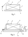
- 10 denotes a total of one batch for a subsequent one Heat treatment.
- the batch 10 comprises a metallic one Workpiece 11, which is preferably on a grate 12.
- On Thermocouple 13 is at a suitable location on or in Workpiece 11 attached.
- a thermal wire leads from the thermocouple 13 14 to a first connecting element 15.
- the first connecting element 15 hangs still loose on the thermal wire 14. This arrangement is also called “Towing element” called.
- thermocouple 13 understood.
- the invention can instead of the temperature of the Workpiece also detects another parameter of the workpiece be, for example, its carburizing state, its Nitriding state, its conductivity, its electrical Resistance, the electromagnetic properties of which For example, the permeability or the like.
- these detected parameters can also be linked together or converted to the treatment medium with auxiliary variables obtained in this way, for example a treatment atmosphere or a To control the treatment bath.
- the first Connecting element 15 is here on a second connecting element 20 infected.
- the second connecting element 20 forms a component a moving device 25.
- the moving device 25 comprises a holder, for example a fork 26 on which the Batch 10 or the workpiece 11 is turned off immediately.
- the second connecting element 20 is preferably on the fork 26 attached.
- the moving device 25 can be moved by means of a movement unit 27, which is indicated extremely schematically in FIG. 2 is to be moved in space.
- a movement unit 27 indicated. The one in the drawing plane the vertical axis lying there is with z and the horizontal axis designated with x.
- the connecting elements 15 and 20 are designed so that they in the illustration according to FIG. 2 plugged together in the x direction can be, as further below with reference to FIGS. 7 and 8 will be explained in more detail.
- the batch placed on the moving device 25 is now 3, in a heat treatment system 30 retracted.
- the displacement device 25 moves into a Treatment chamber 31, for example an oven chamber.
- the treatment chamber 31 is closed at the bottom by a bottom 32, of which there are several in the vertical direction Extend supports 33.
- a bottom 32 of which there are several in the vertical direction Extend supports 33.
- Fig. 3 on the left is a fixed point 34 indicated in a boundary wall of the treatment chamber 31.
- a third connecting element 35th is indicated in a boundary wall of the treatment chamber 31.
- the third connecting element 35 is one in the vertical direction provide upward-facing contact element, as further are explained in detail below with reference to FIGS. 7 and 8 becomes.
- the fork can now 26 can be moved to the right in the x direction. This will the connection between the second connecting element 20 and solved the first connecting element 15. Because the x direction is on the z-direction is vertical, is caused by this movement of the frame 26 the mechanical / electrical connection between the first connecting element 15 and the third connecting element 35 not affected.
- the fork 26 can after loosening the connection between the Elements 15 and 20 laterally from the treatment chamber 31 be brought out.
- Fig. 5 shows the state in which in the Treatment chamber 31 only has workpiece 11 with grate 12 is available.
- the moving device 25 with the fork 26 is on the other hand removed from the treatment chamber 31, in particular because around the elements of the moving device 25 is not an unnecessary one Suspend heat treatment in the treatment chamber 31.
- a vacuum-tight partition 43 is on the other hand the connection of fixed point 34 and batch 10, as in Fig. 6 indicated schematically. This means that only the Thermal wire 14 is guided through the thermal insulation 42, while the connecting elements 15, 35 between the thermal insulation 42 and the vacuum-tight insulation 43 are located.
- the invention is not limited to any one special type of heat treatment plants or furnaces limited is. It can therefore be used both in so-called atmosphere furnaces are used, i.e. systems with atmospheric pressure work, as well as with so-called vacuum systems, i.e. Heat treatment equipment, where the workpieces are vacuum-tight be completed.
- the heat treatment can now take place in the treatment chamber 31 be initiated.
- 31 the workpiece in a gaseous or liquid treatment medium is suspended, for example one indicated by 44 Treatment atmosphere created.
- the treatment atmosphere 44 can be from heated air, a heated inert gas or a chemically active and / or heated atmosphere, like this in the technique of heat treatment metallic Workpieces are generally known. Even the use of a ionized gas atmosphere (plasma) is in this context possible.
- the Treatment chamber 31 only be a heating chamber, so that the Treatment atmosphere 44 consists of heated inert gas.
- the treatment chamber 31 can be part of a larger heat treatment plant 30, in the example in addition to the treatment chamber designed as a heating chamber 31 a quenching chamber 45 is also arranged.
- a quenching chamber 45 is also arranged between Chambers 31, 45 arranged between Chambers 31, 45 .
- the travel device indicated by 25a which is a movement of the batches towards the example indicated arrows 25b, 25c and 25d. So is it is in particular possible to carry out the batches in the horizontal direction 25b, 25d to move between heating chamber 31 and quenching chamber 45 and / or then in quench chamber 45 down 25c into one Lower quench bath.
- the batches 10 can be in the horizontal direction 25b, 25d through doors 46 and 47 in the chambers 31, 45 loaded and unloaded.
- the invention is therefore in contrast to the prior art possible, the batches in any number of treatment chambers to connect one after the other fully automatically, regardless of whether the chambers are cold or warm or whether they are with a gas or are filled with a liquid.
- the numerical control of the traversing device 25 allows the corresponding contact points with high Precision approach.
- the constructive design of the connecting elements 15, 20, 35 allows the transportation process inevitable tolerances in positioning accuracy by means of conical lead-in chamfers and / or spring-loaded shock absorbers to compensate. The variability of heat treatment there are therefore no limits.
- a controller is also shown schematically at 48 indicated.
- the controller 48 is on the input side to the connecting elements 15, 35 connected and receiving in this way a measurement signal from the thermocouple 13.
- the output side controls the Controller 48 a heater 49 so that the temperature of the treatment atmosphere 44 a predetermined by this closed control loop Heating or cooling profile can be readjusted.
- the temperature control can be set precisely because the heat transfer between the Treatment atmosphere 44 and the workpiece 11 no longer matter plays.
- thermocouple 13 instead of the thermocouple 13 other sensors can also be used, physical and / or chemical parameters on the workpieces 11 to measure, so that the treatment atmosphere 44 then with their physical and / or chemical properties accordingly can be adjusted.
- Fig. 7 shows a variant of the embodiment according to the Fig. 1 to 6.
- the same elements are with the same reference numerals has been provided, to distinguish each Reference numerals a 'was added.
- the displacement device 25 ' comprises a fork 26'.
- the fork 26 ' is open to the right in FIG. 7.
- the fork 26 ' bears immediately, i.e. without a grate in between, the workpiece 11 '.
- the workpiece 11 ' has a recess or bore into which the thermocouple 13 'is inserted is. This way the temperature inside the workpiece detected.
- the movement unit is located at the base of the fork 26 ' 27 ', which in turn can be moved in at least two axes x and z is.
- a fixed point 34 'outside the plane 42' carries on it Top of the second connecting element 20 '.
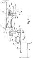
- FIG. 8 and 9 are details of the connecting elements 15, 20 and 35 are shown.
- 8 shows the connecting elements 15, 20 and 35 in a detached state as a side view (partially broken open) while Fig. 9 the connecting elements 15, 20 and 35 in the assembled state in a top view.
- the first connecting element 15 comprises a tube 50 from which the connecting cable 14 emerges.
- the tube 50 which at the same time as Kink protection is used and can also be elastic, is on a first bracket 51 made of electrically non-conductive Material attached.
- the first bracket 51 carries on its underside first contact shoes 52a, 52b in a parallel arrangement.
- Recesses 53a, 53b are provided in the contact shoes 52, 52b.
- the recesses 53a, 53b are on their underside Provide insertion bevels, of which Fig. 8 represents one with 54a.
- the associated axis of the recess 53a is there with 55a.
- the contact shoes 52a, 52b are at their in FIGS. 8 and 9 right side with horizontally protruding pins 58a, 58b Mistake.
- first bracket 51 can also be directed horizontally Contact tongues 57a, 57b may be arranged parallel to the Plug pins 58a, 58b are directed.
- the second connecting element 20 comprises on its upper side a second bracket 60 made of electrically non-conductive material, on the underside of which two arranged parallel to each other Contact shoes 61a, 61b are attached.
- a second bracket 60 made of electrically non-conductive material, on the underside of which two arranged parallel to each other Contact shoes 61a, 61b are attached.
- connection point 63a for the removal of a electrical signals can be provided if in individual cases is desired, the signal of the thermocouple 13 on the Transfer device 25 to the outside.
- the contact shoes 61a, 61b have horizontal receiving bores 64a, 64b, the horizontal distance of which horizontal distance of the pins 58a, 58b on the first connecting element 15 corresponds to. 8 shows the one shown there Receiving hole 64a provided at the left end Entry slope 65a and an axis 66a.
- horizontally directed contact tongues can 67a, 67b which are arranged with the contact tongues 57a, 57b of the first connecting element 15 together a closed can make electrical contact.
- the contact tongues For this reason, 67a, 67b are also parallel to the Plug pins 58a, 58b or the receiving bores 64a, 64b aligned.
- the third connecting element 35 comprises two horizontal and mutually parallel contact plates 70a, 70b with electrical Connection points are provided, of which Fig. 8 one with 71a shows.
- Microswitches 72a, 72b are located on the top of the contact plates 70a, 70b one microswitch 72a, 72b each with connection points 73a, 73b.
- touch elements 74a, 74b of the microswitches 72a, 72b are touch elements 74a, 74b of the microswitches 72a, 72b.
- Microswitches 72a, 72b are vertically spaced apart pins 75a, 75b pointing upwards, their horizontal spacing the horizontal distance between the recesses 53a, 53b corresponds to the first connecting element 15.
- microswitches 72a, 72b simple spring elements can also be used be used. These spring elements then have none electrical function but only that of the Microswitches 72a, 72b have a resilient function. If namely in practical use of the device according to the invention Connecting elements 15 and 35 are to be joined together, as already mentioned, the starting accuracies are too consider. If despite high approach accuracy when approaching the connecting elements 15 and 35, the axes 55a, 55b the contact shoes 52a, 52b not exactly with the axes of the pins 75a, 75b are aligned, so the required tolerance compensation be effected by a spring element that is perpendicular to the Axes 55a, 55b stands.
- the second connecting element 20 had already been used manually the first connecting element 15 has been connected by this with the pins 58, 58a in the receiving bores 64a, 64b was inserted (arrow 81). The introduction of the pins 58a, 58b or their centering was thereby through the lead-in chamfers 65a relieved.
- the electrical connection preferably by a positive connection and thus a contact between the pin 75 and the recesses 53 manufactured.
- the plug 58 have together with the mounting holes 64 only a mechanical holding function.
- the connecting elements 15 and 35 also separate contact tongues be provided, as is shown below using the 7 or the contact tongues 57th and 67 will be explained.
- the Connection between the first connecting element 15 and the second Connecting element 20 can be restored by the second Connecting element 20 in the illustration according to FIG. 8 from the right is approached to the pin 58.
- the first connecting element can then also move the frame 26 upwards 15 again in the vertical direction from the third connecting element 35 can be lifted off.
- connection can be done in this way between the connecting elements 15, 20 and 35 exclusively produced or solved by the method of the moving device 25 become.
- the electrical contact is made by abutting one another Contact surfaces, produced by frictional engagement and / or positive engagement. Very low measuring voltages can also be obtained in this way safely transmitted in the mV range.
- the fork 26 'by means of the movement unit Move 27 'to the right in Fig. 7, as with an arrow located.
- the first connecting element 15 ' is on the fixed point 34 'positioned that the axes 66a, 66b of the second contact shoes 61a, 61b with the axes of the pins 58a, 58b s worn.
- the first connecting element 15 'thus moves in the direction Engagement with the second connecting element 20 ', as with a Arrow 81 indicated in Fig. 8.
- the electrical Connection between the connecting elements 15 and 20 is preferred through the pair of contact tongues 57a / 67a or 57b / 67b.
- the plug pin 58 with the mounting holes 64 also have only a mechanical holding function in this case. In the exemplary embodiment according to FIG. 7, this also applies to the Pin 75 in connection with the recesses 53.
- the number of pairs of contact tongues or Pin / recess pairs is as large as the number of used Thermocouples 13.
- the connecting elements 15, 20 and 35 are therefore also kinematic can be exchanged without changing the scope of the present Invention blows up. It is only important that the respective Connections in the treatment chambers made automatically be by the moving device 25 or 25 'the corresponding Contacts closes or opens.
Landscapes
- Chemical & Material Sciences (AREA)
- Engineering & Computer Science (AREA)
- Materials Engineering (AREA)
- Thermal Sciences (AREA)
- Crystallography & Structural Chemistry (AREA)
- Mechanical Engineering (AREA)
- Physics & Mathematics (AREA)
- Metallurgy (AREA)
- Organic Chemistry (AREA)
- Waste-Gas Treatment And Other Accessory Devices For Furnaces (AREA)
- Tunnel Furnaces (AREA)
- Pressure Welding/Diffusion-Bonding (AREA)
- Heat Treatments In General, Especially Conveying And Cooling (AREA)
- Heat Treatment Of Articles (AREA)
Description
- Fig. 1
- eine schematische Seitenansicht eines auf einem Rost befindlichen Werkstücks, das erfindungsgemäß mit einem Sensor bestückt ist;
- Fig. 2
- das bestückte Werkstück gemäß Fig. 1, bei dem der Rost auf einem Rahmen einer Verfahreinrichtung abgesetzt ist;
- Fig. 3
- die Anordnung gemäß Fig. 2 in einer Wärmebehandlungskammer in einer ersten Arbeitsstellung;
- Fig. 4
- eine Darstellung, ähnlich Fig. 3, jedoch für eine zweite Arbeitsstellung;
- Fig. 5
- eine Darstellung, ähnlich Fig. 3 oder 4, jedoch für eine dritte Arbeitsstellung;
- Fig. 6
- eine Seitenansicht, äußerst schematisiert, auf ein Ausführungsbeispiel einer erfindungsgemäßen Wärmebehandlungsanlage;
- Fig. 7
- eine Variante zum Ausführungsbeispiel gemäß den Fig. 1 bis 6;
- Fig. 8
- eine Seitenansicht, teilweise geschnitten, durch Verbindungselemente, wie sie im Rahmen der vorliegenden Erfindung verwendet werden; und
- Fig. 9
- eine Draufsicht auf die Verbindungselemente gemäß Fig. 8, im zusammengefügten Zustand.
Claims (21)
- Verfahren zum Wärmebehandeln metallischer Werkstücke (11), bei dem die Werkstücke (11) in mindestens einer Behandlungskammer (31) einem Behandlungsmedium (43) ausgesetzt werden, ein Parameter des Werkstücks (11) gemessen und das Behandlungsmedium (43) in Abhängigkeit von dem gemessenen Parameter eingestellt wird, wobei die Werkstücke (11) mittels einer Verfahreinrichtung (25) in der mindestens einen Behandlungskammer (31) verfahren werden und der gemessene Parameter zu einem raumfesten Punkt (34) übertragen wird, dadurch gekennzeichnet, daß der Parameter mittels eines am Werkstück (11) angeordneten und zusammen mit diesem verfahrenen Sensors (13) gemessen und der gemessene Parameter über eine Kabelverbindung mit mechanischen Verbindungselementen (15, 20, 35) vom Werkstück (11) zu dem raumfesten Punkt (34) übertragen wird, und daß die Verbindungselemente (15, 20, 35) durch Verfahren der Verfahreinrichtung (25) zusammengebracht werden und durch Verfahren der Verfahreinrichtung (25) wieder voneinander lösbar sind.
- Verfahren nach Anspruch 1, dadurch gekennzeichnet, daß der Parameter die Temperatur (T) des Werkstücks (11) ist.
- Verfahren nach Anspruch 1 oder 2, dadurch gekennzeichnet, daß der raumfeste Punkt (34) außerhalb der Behandlungskammer (31) liegt.
- Verfahren nach einem oder mehreren der Ansprüche 1 bis 3, dadurch gekennzeichnet, daß die Werkstücke (11) in der Behandlungskammer (31) aufgeheizt werden.
- Verfahren nach einem oder mehreren der Ansprüche 1 bis 3, dadurch gekennzeichnet, daß die Werkstücke (11) in der Behandlungskammer abgeschreckt werden.
- Verfahren nach Anspruch 4 oder 5, dadurch gekennzeichnet, daß die Werkstücke (11) nacheinander in mehreren Behandlungskammern (31, 45) einer Wärmebehandlungsanlage (30) behandelt werden, und daß die Verfahreinrichtung (25) in jeder Behandlungskammer (31, 45) die Verbindungselemente (15, 20, 35) zusammenbringt.
- Vorrichtung zum Wärmebehandeln metallischer Werkstücke (11) in mindestens einer Behandlungskammer (31), mit einem Regler (48) zum Einstellen eines Behandlungsmediums (43) in der mindestens einen Behandlungskammer (31), mit einem an den Regler (48) angeschlossenen Sensor zum Erfassen eines Parameters des Werkstücks (11), und mit einem vom Regler (48) gesteuerten Stellglied zum Beeinflussen des Behandlungsmediums (43), wobei die Werkstücke (11) mit einer Verfahreinrichtung (25) in der Vorrichtung (30) verfahrbar sind, dadurch gekennzeichnet, daß der Sensor am Werkstück (11) festlegbar und zusammen mit diesem verfahrbar ist, daß der Sensor über eine Kabelverbindung mit mechanischen Verbindungselementen (15, 20, 35) mit einem raumfesten Punkt (32) der Vorrichtung (30) verbindbar ist, und daß die Verbindungselemente (15, 20, 35) durch Verfahren der Verfahreinrichtung (25) zusammenbringbar und lösbar sind.
- Vorrichtung nach Anspruch 7, dadurch gekennzeichnet, daß der Sensor ein Thermoelement (13) zum Messen der Temperatur (T) oder ein Element zum Messen einer elektrischen, magnetischen oder chemischen Eigenschaft des Werkstücks (11) ist.
- Vorrichtung nach Anspruch 8, dadurch gekennzeichnet, daß der raumfeste Punkt (34) außerhalb der Behandlungskammer (31) liegt.
- Vorrichtung nach einem oder mehreren der Ansprüche 7 bis 9, dadurch gekennzeichnet, daß der Sensor über ein Kabel (14; 14') mit einem ersten Verbindungselement (15; 15') dauerhaft verbunden ist, und daß das erste Verbindungselement (15; 15') in einer ersten Verfahrachse (z; x) der Verfahreinheit (27; 27') mit einem zweiten Verbindungselement (35; 20') mechanisch verbindbar ist, wobei das zweite Verbindungselement (35; 20') sich an einem raumfesten Punkt (34; 34') befindet.
- Vorrichtung nach einem oder mehreren der Ansprüche 7 bis 10, dadurch gekennzeichnet, daß die Werkstücke (11) auf einer mittels der Verfahreinrichtung (25; 25') verfahrbaren Halterung (26; 26') angeordnet sind, und daß das erste Verbindungselement (15; 15') in einer zweiten Verfahrachse (x; z) der Verfahreinheit (25; 25') mit einem an der Halterung (26; 26') angeordneten dritten Verbindungselement (20; 15') mechanisch verbindbar sind.
- Vorrichtung nach Anspruch 10 und 11, dadurch gekennzeichnet, daß die Verfahrachsen (x/z; z/x) senkrecht aufeinander stehen.
- Vorrichtung nach einem oder mehreren der Ansprüche 10 bis 12, dadurch gekennzeichnet, daß das erste Verbindungselement (15; 15') beim Verbinden mit dem zweiten bzw. dritten Verbindungselement (20, 35; 20'; 35') zugleich mechanisch einen Schalter (72) betätigt.
- Vorrichtung nach einem oder mehreren der Ansprüche 10 bis 12, dadurch gekennzeichnet, daß mindestens eines der Verbindungselemente (15) beim Verbinden in einer Richtung senkrecht zur Verfahrachse (z) des Verbindens gefedert (74) ist.
- Vorrichtung nach einem oder mehreren der Ansprüche 7 bis 14, dadurch gekennzeichnet, daß die Behandlungskammer (31) ein Ofen einer Wärmebehandlungsanlage (30) ist.
- Vorrichtung nach einem oder mehreren der Ansprüche 7 bis 15, dadurch gekennzeichnet, daß die Behandlungskammer eine Abschreckkammer (45) einer Wärmebehandlungsanlage (30) ist.
- Vorrichtung nach einem oder mehreren der Ansprüche 7 bis 16, dadurch gekennzeichnet, daß die mindestens zwei Behandlungskammern (31, 45) eine Wärmebehandlungsanlage (30) umfaßt, daß die Werkstücke (11) mittels der Verfahreinrichtung (25) nacheinander in jede der mindestens zwei Behandlungskammern (31, 45) bringbar sind, wobei in jeder der mindestens zwei Behandlungskammern (31, 45) die Kabelverbindung mittels der Verfahreinrichtung (25) hergestellt wird.
- Vorrichtung nach einem oder mehreren der Ansprüche 7 bis 17, dadurch gekennzeichnet, daß die Behandlungskammer (31) in mindestens einer Ebene (42, 43) abschließbar ist.
- Vorrichtung nach Anspruch 18, dadurch gekennzeichnet, daß die Behandlungskammer (31) in der mindestens einen Ebene (43) vakuumdicht abschließbar ist.
- Vorrichtung nach Anspruch 18 oder 19, dadurch gekennzeichnet, daß die Behandlungskammer (31) in der mindestens einen Ebene (42) thermisch abschließbar ist.
- Vorrichtung nach einem oder mehreren der Ansprüche 18 bis 20, dadurch gekennzeichnet, daß die Kabelverbindung (14, 15, 35) durch die thermisch abschließbare Ebene (42) geführt ist.
Applications Claiming Priority (2)
| Application Number | Priority Date | Filing Date | Title |
|---|---|---|---|
| DE4431608 | 1994-09-06 | ||
| DE4431608A DE4431608C5 (de) | 1994-09-06 | 1994-09-06 | Verfahren und Vorrichtung zum Wärmebehandeln metallischer Werkstücke |
Publications (3)
| Publication Number | Publication Date |
|---|---|
| EP0710727A2 EP0710727A2 (de) | 1996-05-08 |
| EP0710727A3 EP0710727A3 (de) | 1996-11-06 |
| EP0710727B1 true EP0710727B1 (de) | 2002-02-13 |
Family
ID=6527472
Family Applications (1)
| Application Number | Title | Priority Date | Filing Date |
|---|---|---|---|
| EP95113432A Revoked EP0710727B1 (de) | 1994-09-06 | 1995-08-26 | Verfahren und Vorrichtung zum Wärmebehandeln metallischer Werkstücke |
Country Status (3)
| Country | Link |
|---|---|
| EP (1) | EP0710727B1 (de) |
| AT (1) | ATE213280T1 (de) |
| DE (1) | DE4431608C5 (de) |
Family Cites Families (5)
| Publication number | Priority date | Publication date | Assignee | Title |
|---|---|---|---|---|
| DE1816373B1 (de) * | 1968-12-21 | 1970-03-26 | Matthias Ludwig Industrieofenb | Ofenanlage,insbesondere Haubenofenanlage |
| DE3150576C1 (de) * | 1981-12-21 | 1982-12-09 | Friedrich Wilhelm Dipl.-Ing. 7761 Moos Elhaus | Vorrichtung zum Wärmebehandeln von metallischem Gut |
| DE3506131C1 (de) * | 1985-02-22 | 1986-05-22 | Aichelin GmbH, 7015 Korntal-Münchingen | Verfahren zum Waermebehandeln von insbesondere metallischen Werkstuecken und Vorrichtung zur Durchfuehrung des Verfahrens |
| JPH0693438B2 (ja) * | 1986-12-11 | 1994-11-16 | 大日本スクリ−ン製造株式会社 | 基板温度測定装置 |
| DE4233916A1 (de) * | 1992-10-08 | 1994-04-28 | Gautschi Electro Fours Sa | Verfahren und Vorrichtung zur Wärmebehandlung von Wärmgut in einem Industrieofen |
-
1994
- 1994-09-06 DE DE4431608A patent/DE4431608C5/de not_active Expired - Fee Related
-
1995
- 1995-08-26 AT AT95113432T patent/ATE213280T1/de not_active IP Right Cessation
- 1995-08-26 EP EP95113432A patent/EP0710727B1/de not_active Revoked
Also Published As
| Publication number | Publication date |
|---|---|
| ATE213280T1 (de) | 2002-02-15 |
| DE4431608C5 (de) | 2004-02-05 |
| EP0710727A3 (de) | 1996-11-06 |
| DE4431608C2 (de) | 1996-08-29 |
| DE4431608A1 (de) | 1996-03-07 |
| EP0710727A2 (de) | 1996-05-08 |
Similar Documents
| Publication | Publication Date | Title |
|---|---|---|
| EP2989220B1 (de) | Vorrichtung zum presshaerten von bauteilen | |
| DE102009041041B4 (de) | Verfahren und Vorrichtung zum Härten von Werkstücken, sowie nach dem Verfahren gehärtete Werkstücke | |
| EP0422353A2 (de) | Ofen zur partiellen Wärmebehandlung von Werkzeugen | |
| DE102007057410B3 (de) | Mechanismus und Verfahren zur automatisierbaren Verriegelung von Türen, Türkörpern oder Türrahmen horizontaler Koksofenkammern | |
| DE3108336C2 (de) | Gießvorrichtung und- verfahren | |
| EP0460484A2 (de) | Verschlussvorrichtung an einer Wärmebehandlungsanlage | |
| EP3351321A1 (de) | Vorrichtung und verfahren zur additiven fertigung wenigstens eines formkörpers | |
| DE202016100564U1 (de) | Vorrichtung zur Erwärmung von Werkstücken unter Schutzgasatmosphäre | |
| EP3768644A1 (de) | Vorrichtung mit einem ofen und verfahren zu deren verwendung | |
| WO2013124235A2 (de) | Vorrichtung zur wärmebehandlung von lebensmittelprodukten mit integrierter handlingeinrichtung | |
| DE10159170B4 (de) | Polarisierungsvorrichtung und -verfahren | |
| DE4431608C2 (de) | Verfahren und Vorrichtung zum Wärmebehandeln metallischer Werkstücke | |
| DE4336405C2 (de) | Anordnung zum Prüfen von Gegenständen bei unterschiedlichen Temperaturen, insbesondere zur Prüfung bei sich schnell ändernden Temperaturen | |
| WO2016124309A1 (de) | Verfahren, ofeneinrichtung und anlage zum formhärten von werkstücken | |
| EP3631301A1 (de) | Elektromechanische verschlusseinrichtung für gerätetüren | |
| DE102020133920A1 (de) | Vorrichtung und Verfahren zum thermischen Fügen thermoplastischer Kunststoffe | |
| DE1771817B1 (de) | Vorrichtung zur fluchtenden Ausrichtung eines auf einer Ausdrueckmaschine angeordneten Stoessels mit einer Tuerabhebevorrichtung auf die Ofentuer | |
| DE68906405T2 (de) | Vorrichtung zum erwaermen einer probe in einer vakuumkammer. | |
| DE3101351C2 (de) | Vorrichtung zum Härten von metallischen Werkstücken mit einer evakuierbaren Kammer | |
| DE4010353A1 (de) | Verfahren und vorrichtung zum betreiben eines metallurgischen ofens mit selbstbackender elektrode | |
| WO2018073046A1 (de) | Vorrichtung zum form- und kraftschlüssigen halten von scheiben einer einrichtung zur wärmebehandlung von lebensmitteln, insbesondere eines backofens | |
| EP0285781A1 (de) | Verfahren und Vorrichtung zur Erzeugung hoher Temperaturen | |
| DE10030514C1 (de) | Vorrichtung zum Sintern von aluminiumbasierten Sinterteilen | |
| EP3454661B1 (de) | Vorrichtung zur waermebehandlung von lebensmittelprodukten mit beschickungswagen | |
| DE102019120557A1 (de) | Prüfgerät für Warmzugprüfungen |
Legal Events
| Date | Code | Title | Description |
|---|---|---|---|
| PUAI | Public reference made under article 153(3) epc to a published international application that has entered the european phase |
Free format text: ORIGINAL CODE: 0009012 |
|
| AK | Designated contracting states |
Kind code of ref document: A2 Designated state(s): AT FR IT |
|
| PUAL | Search report despatched |
Free format text: ORIGINAL CODE: 0009013 |
|
| AK | Designated contracting states |
Kind code of ref document: A3 Designated state(s): AT FR IT |
|
| 17P | Request for examination filed |
Effective date: 19970329 |
|
| RAP1 | Party data changed (applicant data changed or rights of an application transferred) |
Owner name: AICHELIN GMBH |
|
| 17Q | First examination report despatched |
Effective date: 20001011 |
|
| GRAG | Despatch of communication of intention to grant |
Free format text: ORIGINAL CODE: EPIDOS AGRA |
|
| GRAG | Despatch of communication of intention to grant |
Free format text: ORIGINAL CODE: EPIDOS AGRA |
|
| GRAH | Despatch of communication of intention to grant a patent |
Free format text: ORIGINAL CODE: EPIDOS IGRA |
|
| GRAH | Despatch of communication of intention to grant a patent |
Free format text: ORIGINAL CODE: EPIDOS IGRA |
|
| GRAA | (expected) grant |
Free format text: ORIGINAL CODE: 0009210 |
|
| AK | Designated contracting states |
Kind code of ref document: B1 Designated state(s): AT FR IT |
|
| REF | Corresponds to: |
Ref document number: 213280 Country of ref document: AT Date of ref document: 20020215 Kind code of ref document: T |
|
| ET | Fr: translation filed | ||
| PGFP | Annual fee paid to national office [announced via postgrant information from national office to epo] |
Ref country code: AT Payment date: 20020729 Year of fee payment: 8 |
|
| PGFP | Annual fee paid to national office [announced via postgrant information from national office to epo] |
Ref country code: FR Payment date: 20020829 Year of fee payment: 8 |
|
| PLBQ | Unpublished change to opponent data |
Free format text: ORIGINAL CODE: EPIDOS OPPO |
|
| PLBI | Opposition filed |
Free format text: ORIGINAL CODE: 0009260 |
|
| PLBF | Reply of patent proprietor to notice(s) of opposition |
Free format text: ORIGINAL CODE: EPIDOS OBSO |
|
| 26 | Opposition filed |
Opponent name: IPSEN INTERNATIONAL GMBH Effective date: 20021113 |
|
| PLBF | Reply of patent proprietor to notice(s) of opposition |
Free format text: ORIGINAL CODE: EPIDOS OBSO |
|
| PG25 | Lapsed in a contracting state [announced via postgrant information from national office to epo] |
Ref country code: AT Free format text: LAPSE BECAUSE OF NON-PAYMENT OF DUE FEES Effective date: 20030826 |
|
| PG25 | Lapsed in a contracting state [announced via postgrant information from national office to epo] |
Ref country code: FR Free format text: LAPSE BECAUSE OF NON-PAYMENT OF DUE FEES Effective date: 20040430 |
|
| REG | Reference to a national code |
Ref country code: FR Ref legal event code: ST |
|
| RDAF | Communication despatched that patent is revoked |
Free format text: ORIGINAL CODE: EPIDOSNREV1 |
|
| RDAG | Patent revoked |
Free format text: ORIGINAL CODE: 0009271 |
|
| STAA | Information on the status of an ep patent application or granted ep patent |
Free format text: STATUS: PATENT REVOKED |
|
| 27W | Patent revoked |
Effective date: 20040709 |