EP0710523B1 - Verfahren und Vorrichtung zum Entgräten und Kalibrieren von in einem Umformaggregat geschmiedeten Werkstücken - Google Patents
Verfahren und Vorrichtung zum Entgräten und Kalibrieren von in einem Umformaggregat geschmiedeten Werkstücken Download PDFInfo
- Publication number
- EP0710523B1 EP0710523B1 EP19940117431 EP94117431A EP0710523B1 EP 0710523 B1 EP0710523 B1 EP 0710523B1 EP 19940117431 EP19940117431 EP 19940117431 EP 94117431 A EP94117431 A EP 94117431A EP 0710523 B1 EP0710523 B1 EP 0710523B1
- Authority
- EP
- European Patent Office
- Prior art keywords
- station
- deburring
- burr
- transport
- assembly
- Prior art date
- Legal status (The legal status is an assumption and is not a legal conclusion. Google has not performed a legal analysis and makes no representation as to the accuracy of the status listed.)
- Expired - Lifetime
Links
- 238000000034 method Methods 0.000 title claims description 40
- 238000006073 displacement reaction Methods 0.000 claims description 4
- 230000008878 coupling Effects 0.000 claims description 3
- 238000010168 coupling process Methods 0.000 claims description 3
- 238000005859 coupling reaction Methods 0.000 claims description 3
- 230000005484 gravity Effects 0.000 claims description 2
- 125000004122 cyclic group Chemical group 0.000 claims 1
- 238000009966 trimming Methods 0.000 description 13
- 238000009412 basement excavation Methods 0.000 description 7
- 238000005242 forging Methods 0.000 description 6
- 238000005266 casting Methods 0.000 description 4
- 238000010438 heat treatment Methods 0.000 description 3
- 238000004519 manufacturing process Methods 0.000 description 2
- 206010034016 Paronychia Diseases 0.000 description 1
- 235000014676 Phragmites communis Nutrition 0.000 description 1
- 238000007630 basic procedure Methods 0.000 description 1
- 230000009286 beneficial effect Effects 0.000 description 1
- 238000005520 cutting process Methods 0.000 description 1
- 238000005516 engineering process Methods 0.000 description 1
- 239000000834 fixative Substances 0.000 description 1
- 230000037406 food intake Effects 0.000 description 1
- 238000002372 labelling Methods 0.000 description 1
- 238000000926 separation method Methods 0.000 description 1
Images


Classifications
-
- B—PERFORMING OPERATIONS; TRANSPORTING
- B21—MECHANICAL METAL-WORKING WITHOUT ESSENTIALLY REMOVING MATERIAL; PUNCHING METAL
- B21J—FORGING; HAMMERING; PRESSING METAL; RIVETING; FORGE FURNACES
- B21J13/00—Details of machines for forging, pressing, or hammering
- B21J13/08—Accessories for handling work or tools
-
- B—PERFORMING OPERATIONS; TRANSPORTING
- B21—MECHANICAL METAL-WORKING WITHOUT ESSENTIALLY REMOVING MATERIAL; PUNCHING METAL
- B21K—MAKING FORGED OR PRESSED METAL PRODUCTS, e.g. HORSE-SHOES, RIVETS, BOLTS OR WHEELS
- B21K1/00—Making machine elements
- B21K1/76—Making machine elements elements not mentioned in one of the preceding groups
- B21K1/766—Connecting rods
-
- B—PERFORMING OPERATIONS; TRANSPORTING
- B23—MACHINE TOOLS; METAL-WORKING NOT OTHERWISE PROVIDED FOR
- B23Q—DETAILS, COMPONENTS, OR ACCESSORIES FOR MACHINE TOOLS, e.g. ARRANGEMENTS FOR COPYING OR CONTROLLING; MACHINE TOOLS IN GENERAL CHARACTERISED BY THE CONSTRUCTION OF PARTICULAR DETAILS OR COMPONENTS; COMBINATIONS OR ASSOCIATIONS OF METAL-WORKING MACHINES, NOT DIRECTED TO A PARTICULAR RESULT
- B23Q7/00—Arrangements for handling work specially combined with or arranged in, or specially adapted for use in connection with, machine tools, e.g. for conveying, loading, positioning, discharging, sorting
- B23Q7/03—Arrangements for handling work specially combined with or arranged in, or specially adapted for use in connection with, machine tools, e.g. for conveying, loading, positioning, discharging, sorting by means of endless chain conveyors
- B23Q7/035—Arrangements for handling work specially combined with or arranged in, or specially adapted for use in connection with, machine tools, e.g. for conveying, loading, positioning, discharging, sorting by means of endless chain conveyors on which work holders are fixed
Definitions
- the present invention relates to a method and a Device for deburring and calibrating in a forming unit forged workpieces.
- Forming unit forged workpiece is from a first operator by means of pliers by hand Forming unit removed, placed on a transfer table, by a second operator by means of a Pliers picked up and fed to the deburring unit. After this Detaching the burr from the workpiece removes the workpiece from the second operator again recorded and sent to the Hand over calibration unit.
- document GB-A-1 157 944 discloses a method for Deburring from one forged in a forming station Workpiece, with the following steps:
- Document GB-A-1 157 944 further discloses an endless one At least conveyor device forming conveyor a transport recording in circulation, facilities for intermittent movement of the transport recording or Transport shots from one loading station to one Forming station, from this to a deburring station and from there to a ridge removal station and back to the loading station, and a gripping device with which the ridge in the Burr removal station can be lifted off the transport holder.
- the invention has for its object conventional Procedures for deburring and calibrating in one Automate forming unit forged workpiece, and in such a way that the individual process steps with technically simple means and in a reliable manner can be realized.
- the invention is based on the idea of automation not on a simple automatic transport between the forming unit, the deburring unit and the Limit calibration unit, but one completely creating a new workflow that fixes problems for avoid the workpieces before each work step and without additional effort also the removal of the workpiece detached ridges involved and accomplished.
- the workpieces are immediately after the Forging process in the forming unit on the transport holder fixed in position and only after separation from the ridge of of the transport recording. This has the consequence that the workpieces produced by the forging process up to Cutting off the burr, especially when handing it over on the deburring unit and when placing it in the deburring unit no longer have to be fixed in position, which is the case with the given conditions (glowing condition) and the strong differing contours of the ridge extremely difficult and would be expensive.
- the task of transport recording not finished after removing the workpiece. Rather, the transport recording after Removing the workpieces used to remove the burr and thus takes on a double function.
- Another advantage of the endless conveyor line is that a separate return transport of the transport recordings to Charging station after use is no longer necessary.
- a particularly expedient procedure results from if when transferring the deburred workpiece from the deburring unit into the calibration unit the deburred Workpiece in a first step in a waiting station transferred and then in a second step from the Waiting station is moved into the calibration unit.
- the object of the present invention is also a technically simply constructed device for performing the Procedure to create, despite the rough operation works reliably.
- the ring conveyor is according to the invention for cyclical conveying of three equally spaced Transport recordings set up.
- Constellation of the device must be in relation to the Conveyor line also the loading station, the delivery station and the burr removal station at equal distances from each other be arranged.
- the loading device in be designed in many different ways.
- a particularly beneficial one Design arises, however, if the Loading device two pivotable about a vertical axis, diametrically opposite and has radially extending arms, the free ends of which Capture the transport shots are set up.
- Such Feeding devices, also double arm grippers are technically simple and are suitable especially for rough operation in the forging area.
- the loading device can be in any driven in any way. It is advantageous however, if the arms have a piston-cylinder arrangement are pivotable. In this way there is no rotational movement possible by 360 °. For the loading process however, a swivel movement of 180 ° is usually sufficient from when using a piston-cylinder arrangement as Back and forth movement, i.e. as a pivoting movement first one and then designed in the opposite direction can be.
- the arms are driven by a piston-cylinder arrangement is technically feasible with simple means, inexpensive to manufacture and good against rough influences in the To protect operation.
- the deburring unit and the calibration unit can also designed according to the invention in various ways become. However, it is advantageous if both units with are equipped with a common drive. Is expedient it the deburring unit and the calibration unit in a double press with a distance between them Combine deburring and calibration station. At a Such double press, it is possible to use the waiting station between the deburring station and the calibration station to arrange and thus further simplify the structure.
- For transferring the workpieces from the deburring unit into the Waiting station or from the waiting station into the calibration unit can basically any transport or Sliding device can be used because it is after Removing the burr is usually easier that To grasp the workpiece.
- the transport admission is basically after the forging workpiece designed. It can have any suitable shape. It is advantageous to take the transport as Form plate and thus their handling too facilitate.
- the invention is the transport recording as a wiper plate trained for the ridge.
- the scraper plate during the deburring process in the deburring unit part of a deburring tool and has with it a multiple function according to the invention.
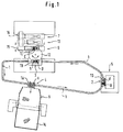
- the ring conveyor 1 shown in Fig. 1 for example can be designed as a chain conveyor in the present exemplary embodiment for cyclical conveying of a total of four transport shots TA, TB, TC and TD, with three transport shots (in the phase according to Fig. 1, the transport recording TA, TB and TD) in the same Distances to each other are promoted and the fourth Transport recording (in the phase shown in FIG. 1, the Transport admission TC) to carry out the deburring process is located in the deburring unit 6.
- the transport receptacles TA to TC are preferably plate-shaped trained and possess on their underside and / or not in the area of their narrow sides Coupling means shown with which they on the ring conveyor 1 coupled or fixed in the individual stations or also in the area of the deburring unit 6 (as later will be described) removed from the ring conveyor 1 can be.
- the transport receptacles TA to TD are on the top each with unspecified and illustrated Fasteners equipped with which workpieces A to D in the transport and described below Operations against slipping in a horizontal plane are kept on the transport recordings.
- This fixative usually consist of recesses or projections on the top of the transport shots.
- the basic procedure for a device is as follows describe. Because during operation of the device the four transport shots with the respective workpieces and burrs distributed in the different stations or aggregates are in the following Description of the passage of a single workpiece For the sake of simplicity, the reference numerals of the other Transport shots, workpieces and burrs in the various stations or units used and Labeling in brackets:
- a drop forging hammer manufactured workpiece D such as a connecting rod
- the ring conveyor 1 started and the workpiece with Burr still in the glowing state in the delivery station 3 promoted.
- the workpiece (B) with ridge (b) together with its transport holder (TB) via a loading device 12 from the ring conveyor 1 lifted off and taken into the deburring unit 6.
- the burr (c) from the workpiece (c) separated and the workpiece without burr in a waiting station 13 moves.
- the calibration unit 7, calibrated in it, i.e. and from there one immediately fed further heat treatment, not on here will be discussed further.
- the one in the trimming unit 6 lying on the transport holder Burr is in the feeder 12 in the Dispensing station 3 is conveyed back and arrives from there with the next cycle over the ring conveyor to the burr removal station 4th
- the empty transport holder arrives (TA) from the burr removal station 4 back to the Loading station 2, in which they then with one in the forming unit 5 manufactured new workpiece with burr so that the above-described duty cycle is repeated can start.
- the deburred workpiece A in the fourth phase (Fig. 2.4) via a first transport device 15 (only indicated in Fig. 1) from the trimming unit 6 removed and transferred to the waiting station 13.
- the ridge a remains on the transport holder TA.
- the ring conveyor 1 from the loading station 2 the following Workpiece B with burr b on the transport holder TB delivered and in the delivery station 3 by the Loading device 12 taken over.
- the trimming unit forms 6 with the calibration unit 7 in the present exemplary embodiment one unity.
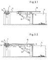
- FIGS. 3.1 to 3.4 there is the gripping device 8 in the burr removal station 4 from one Stand 17 on which a tilting plate 18 via a joint 19 is articulated.
- the tilting plate 18 can, as shown in FIGS. 3.1 to 3.4 emerges from a tilting cylinder 20 their horizontal position raised to an inclined position become.
- the tilting plate 18 is in a not shown Guide slidably mounted in its plate level. Under the tilting plate is a displacement cylinder parallel to the plate level 21 arranged with which the tilting plate 18th is slidable in its guidance in the plate plane.
- the arrangement is such that the tilting plate 18 between the burr removal station 4 of the ring conveyor 1 and the collecting container 14 can be pushed back and forth.
- the tilting plate 18 equipped with an excavation fork 22 which for The undertaking of each on its transport recording (e.g. TA) delivered burr (e.g. a) is set up.
- transport shots are for this purpose provided with recesses 23 into which the excavation fork 22nd can be inserted.
- the first phase (Fig. 3.1) is through the ring conveyor 1 for example the transport mount TA with the ridge a in the burr removal station 4 promoted.
- this first one Phase is the tilt plate 18 together with the Excavation fork 22 in its retracted position.
- the tilt cylinder 20 activated and the tilt plate 18 raised.
- the displacement cylinder 21 retracted (Fig. 3.4) and so that the tilt plate 18 together with the excavation fork 22 in transferred the withdrawn position.
- the tilt cylinder 22 is actuated and the tilt plate 18 together with the excavation fork 22 in the starting position (see Fig.3.1).
- the gripping device 8 is then ready for another removal process and that of Burr-empty transport recording can be done in the following Cycle from the ring conveyor 1 in the loading station 2 to Inclusion of a new workpiece generated in the forming unit 5 be transported with burr.
Landscapes
- Engineering & Computer Science (AREA)
- Mechanical Engineering (AREA)
- Forging (AREA)
Description
- Fördern mindestens einer Transportaufnahme im Umlauf über einen eine endlose Förderstrecke bildenden Rinförderer von einer Beladestation zu einer Abgabestation, von dieser zu einer Gratentnahmestation und von dort zurück zur Beladestation;
- Auflegen jeweils mindestens eines, im Umformaggregat geschmiedeten, mit Grat versehenen Werkstückes auf die Transportaufnahme in der Beladestation;
- Ankoppeln der Transportaufnahme mit dem Werkstück am Ringförderer;
- Fördern der Transportaufnahme mit dem Werkstück von der Beladestation zur Abgabestation;
- Abheben der Transportaufnahme mit dem werkstück vom Ringförderer über eine Beschickungsvorrichtung;
- Übergeben der Transportaufnahme mit dem Werkstück an ein Abgrataggregat;
- Trennen des Werkstückes vom Grat und Überführen des Werkstückes in ein Kalibrieraggregat;
- Ausfördern des abgetrennten Grates auf der Transportaufnahme über die Beschickungsvorrichtung aus dem Abgrataggregat in die Abgabestation und Fördern der Transportaufnahme mit Grat über den Ringförderer von der Abgabestation zur Gratentnahmestation;
- Abnehmen des Grates von der Transportaufnahme in der Gratentnahmestation und Rückführen der leeren Transportaufnahme über den Ringförderer zur Beladestation.
- ein Grat eines ersten Werkstückes in der Gratentnahmestation von der ersten Transportaufnahme abgenommen,
- eine zweite Transportaufnahme mit dem Grat eines zweiten Werkstückes in der Abgabestation von dem Abgrataggregat übernommen, und
- ein viertes Werkstück mit Grat in der Beladestation
auf die vierte Transportaufnahme aufgelegt wird,
wobei beim anschließenden Fördervorgang - die erste Transportaufnahme leer in die Beladestation,
- die zweite Transportaufnahme mit dem Grat des zweiten Werkstückes in die Gratentnahmestation, und
- die vierte Transportaufnahme mit dem vierten Werkstück in die Abgabestation gefördert werden.
- einem die endlose Förderstrecke bildenden Ringförderer für mindestens eine Transportaufnahme, wobei der Ringförderer zum taktweisen Fördern von jeweils drei in gleichen Abständen zueinander angeordneten Transporaufnahmen eingerichtet ist,
- Einrichtungen, die die Transportaufnahme bzw. die Transportaufnahmen von einer Belade- zu einer Abgabestation und von dort zu einer Gratentnahmestation und zurück zur Beladestation taktweise fortbewegen,
- einer Beschickungsvorrichtung in der Abgabestation, über die jeweils die aus der Beladestation ankommende Transportaufnahme mit einem in einem Umformaggregat geschmiedeten mit Grat versehenen Werkstück in ein Abgrataggregat eingefördert, sowie die Transportaufnahme mit Grat aus dem Abgrataggregat ausgefördert wird,
- einem Kalibrieraggregat, in das das jeweils entgratete Werkstück aus dem Abgrataggregat überführt wird,
- sowie einer Greifeinrichtung, mit der der Grat in der Gratentnahmestation von der Transportaufnahme abhebbar und einem Sammelbehälter zuführbar ist.
- Fig. 1
- zeigt in einer Draufsicht schematisch eine Gesamtansicht der Vorrichtung zur Durchführung des Verfahrens, die eine endlose Förderstrecke in Form eines Ringförderers 1, sowie in gleichen Abständen zueinander am Ringförderer 1 angeordnete Stationen aufweist, nämlich eine Beladestation 2, eine Abgabestation 3 und eine Gratentnahmestation 4 mit den jeweils in diesen Stationen angeordneten Aggregaten, nämlich einem Umformaggregat im Bereich der Beladestation 2, einem Abgrataggregat 6 mit Kalibrieraggregat 7 im Bereich der Abgabestation 3, sowie einer Greifvorrichtung 8 im Bereich der Gratentnahmestation 4.
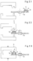
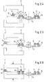
- Fig. 2.1 bis 2.9 zeigen
- in neun Arbeitsphasen schematisch den Arbeitsablauf im Bereich der Abgabestation 3 in dem Abgrataggregat 6 und dem Kalibrieraggregat 7, und
- Fig. 3.1 bis 3.4 zeigen
- in vier Arbeitsphasen schematisch den Arbeitsablauf im Bereich der Gratentnahmestation 4 an der Greifvorrichtung 8.
Claims (19)
- Verfahren zum Entgraten und Kalibrieren von in einem Umformaggregat geschmiedeten Werkstücken, gekennzeichnet durch folgende Schritte:Fördern mindestens einer Transportaufnahme (TA, TB, TC oder TD) im Umlauf über einen eine endlose Förderstrecke bildenden Ringförderer (1) von einer Beladestation (2) zu einer Abgabestation (3), von dieser zu einer Gratentnahmestation (4) und von dort zurück zur Beladestation (2);Auflegen jeweils mindestens eines, im Umformaggregat geschmiedeten, mit Grat (a, b, c oder d) versehenen Werkstückes (A, B, C oder D) auf die Transportaufnahme (TA bis TD) in der Beladestation (2);Ankoppeln der Transportaufnahme (TA bis TD) mit dem Werkstück (A bis D) am Ringförderer (1);Fördern der Transportaufnahme (TA bis TD) mit dem Werkstück (A bis D) von der Beladestation (2) zur Abgabestation (3);Abheben der Transportaufnahme (TA bis TD) mit dem Werkstück (A bis D) vom Ringförderer (1) über eine Beschickungsvorrichtung (12);Übergeben der Transportaufnahme (TA bis TD) mit dem Werkstück (A bis D) über die Beschickungsvorrichtung (12) an ein Abgrataggregat (6);Trennen des Werkstückes (A bis D) vom Grat (a bis d) und Überführen des Werkstückes (A bis D) in ein Kalibrieraggregat (7);Ausfördern des abgetrennten Grates (a bis d) auf der Transportaufnahme (TA bis TD) über die Beschickungsvorrichtung (12) aus dem Abgrataggregat (6) in die Abgabestation (3) und Fördern der Transportaufnahme (TA bis TD) mit Grat (a bis d) über den Ringförderer (1) von der Abgabestation (3) zur Gratentnahmestation (4);Abnehmen des Grates (a bis d) von der Transportaufnahme (TA bis TD) in der Gratentnahmestation (4) und Rückführen der leeren Transportaufnahme über den Ringförderer (1) zur Beladestation (2).
- Verfahren nach Anspruch 1, gekennzeichnet durch taktweises Fördern von vier Transportaufnahmen (TA, TB, TC und TD) im Umlauf über den Ringförderer (1),
wobei im Stillstand jeweils gleichzeitigein Grat (a) eines ersten Werkstückes (A) in der Gratentnahmestation (4) von der ersten Transportaufnahme (TA) abgenommen,eine zweite Transportaufnahme (TB) mit dem Grat (b) eines zweiten Werkstückes (B) in der Abgabestation (3) von dem Abgrataggregat (6) übernommen, undein viertes Werkstück (D) mit Grat (d) in der Beladestation (2) auf die vierte Transportaufnahme (TD) aufgelegt wird,
wobei beim anschließenden Fördervorgangdie erste Transportaufnahme (TA) leer in die Beladestation (2),die zweite Transportaufnahme (TB) mit dem Grat (b) des zweiten Werkstückes in die Gratentnahmestation (4), unddie vierte Transportaufnahme (TD) mit dem vierten Werkstück (D) in die Abgabestation (3) gefördert werden. - Verfahren nach Anspruch 1 oder 2,
dadurch gekennzeichnet, daß
beim Überführen des jeweils entgrateten Werkstückes von dem Abgrataggregat (6) in das Kalibrieraggregat (7) das entgratete Werkstück in einem ersten Schritt in eine Wartestation (13) überführt und dann in einem zweiten Schritt von der Wartestation (13) in das Kalibrieraggregat (7) verschoben wird. - Verfahren nach Anspruch 2 und 3,
dadurch gekennzeichnet, daß
in der Phase des ersten Schrittes beim Überführen des entgrateten dritten Werkstückes von dem Abgrataggregat (6) in die Wartestation (13) die zweite Transportaufnahme mit dem Grat des zweiten Werkstückes aus der Abgabestation (3) in die Gratentnahmestation (4) und das vierte Werkstück mit Grat auf der vierten Transportaufnahme von der Beladestation (2) in die Abgabestation (3) gefördert werden. - Verfahren nach Anspruch 2, 3 und 4,
dadurch gekennzeichnet, daß
in der Phase des zweiten Schrittes beim Überführen des entgrateten dritten Werkstückes von der Wartestation (13) in das Kalibrieraggregat (7) das vierte Werkstück mit dem Grat mit der vierten Transportaufnahme aus der Abgabestation (3) in das Abgrataggregat (6) und die dritte Transportaufnahme mit dem Grat des dritten Werkstückes aus dem Abgrataggregat (6) in die Abgabestation (3) gefördert werden. - Verfahren nach Anspruch 1 oder 2,
dadurch gekennzeichnet, daß
der Grat (a) in der Gratentnahmestation (4) unterfangen und im Anschluß daran von der Transportaufnahme (TA) abgehoben wird. - Verfahren nach Anspruch 6,
dadurch gekennzeichnet, daß
der Grat beim Abheben geneigt und unter Ausnutzung der Schwerkraft über eine Rutsche in einen Sammelbehälter (14) gefördert wird. - Vorrichtung zur Durchführung des Verfahrens nach Anspruch 1 oder 2, miteinem die endlose Förderstrecke bildenden Ringförderer (1) für mindestens eine Transportaufnahme (TA, TB, TC oder TD), wobei der Ringförderer (1) zum taktweisen Fördern von jeweils drei in gleichen Abständen zueinander angeordneten Transportaufnahmen (TA, TB, TD) eingerichtet ist,Einrichtungen, die die Transportaufnahme bzw. die Transportaufnahmen von einer Beladestation (2) zu einer Abgabestation (3) und von dort zu einer Gratentnahmestation (4) und zurück zur Beladestation (2) taktweise fortbewegen,einer Beschickungsvorrichtung (12) in der Abgabestation (3), über die jeweils die aus der Beladestation (2) ankommende Transportaufnahme (TA bis TD) mit einem in einem Umformaggregat (5) geschmiedeten, mit Grat (a, b, c oder d) versehenen Werkstück (A, B, C oder D) in ein Abgrataggregat (6) eingefördert, sowie die Transportaufnahme mit Grat aus dem Abgrataggregat (6) ausgefördert wird,einem Kalibrieraggregat (7), in das das jeweils entgratete Werkstück (A bis D) aus dem Abgrataggregat (6) überführt wird,sowie einer Greifeinrichtung (8), mit der der Grat (a bis d) in der Gratentnahmestation (4) von der Transportaufnahme (TA bis TD) abhebbar und einem Sammelbehälter (14) zuführbar ist.
- Vorrichtung nach Anspruch 8, dadurch
gekennzeichnet, daß die Greifeinrichtung
(8) aus einem Ständer (17), an dem eine Kipp-Platte (18) über ein Gelenk (19) angelenkt ist, besteht. - Vorrichtung nach Anspruch 8,
dadurch gekennzeichnet, daß
der Ringförderer (1) als Kettenbahn-Förderer ausgebildet ist. - Vorrichtung nach Anspruch 8,
dadurch gekennzeichnet, daß
die Beschickungsvorrichtung (12) zwei um eine vertikale Achse verschwenkbare, diametral einander gegenüberliegende und radial verlaufende Arme aufweist, deren freie Enden zum Erfassen der Transportaufnahmen (TA bis TD) eingerichtet sind. - Vorrichtung nach Anspruch 8,
dadurch gekennzeichnet, daß
die Beschickungsvorrichtung (12) als Drehkreuzanordnung ausgebildet ist. - Vorrichtung nach Anspruch 11,
dadurch gekennzeichnet, daß
die Arme über eine Kolben-Zylinder-Anordnung verschwenkbar sind. - Vorrichtung nach Anspruch 8,
dadurch gekennzeichnet, daß
das Abgrataggregat (6) und das Kalibrieraggregat (7) einen gemeinsamen Antrieb aufweisen. - Vorrichtung nach Anspruch 14,
dadurch gekennzeichnet, daß
das Abgrataggregat (6) und das Kalibrieraggregat (7) in einer Doppelpresse mit im Abstand zueinander angeordneten Abgrat- und Kalibrierstationen zusammengefaßt sind. - Vorrichtung nach Anspruch 15,
dadurch gekennzeichnet, daß
eine Wartestation (13) zwischen der Abgratstation und der Kalibrierstation angeordnet ist. - Vorrichtung nach einem oder mehreren der vorhergehenden Ansprüche 8 bis 16,
dadurch gekennzeichnet, daß
zum Überführen der Werkstücke von dem Abgrataggregat (6) in die Wartestation (13) eine erste (15) und zum Verschieben der Werkstücke von der Wartestation (13) in das Kalibrieraggregat (7) eine zweite Transportvorrichtung (16) vorgesehen sind. - Vorrichtung nach einem oder mehreren der vorhergehenden Ansprüche 8 bis 17,
dadurch gekennzeichnet, daß
jede Transportaufnahme (TA bis TC) als Platte ausgebildet ist. - Vorrichtung nach Anspruch 18,
dadurch gekennzeichnet, daß
jede Platte als Abstreiferplatte für den Grat ausgebildet ist, die beim Abgratvorgang in dem Abgrataggregat (6) einen Teil eines Abgratwerkzeuges bildet.
Priority Applications (2)
| Application Number | Priority Date | Filing Date | Title |
|---|---|---|---|
| EP19940117431 EP0710523B1 (de) | 1994-11-04 | 1994-11-04 | Verfahren und Vorrichtung zum Entgräten und Kalibrieren von in einem Umformaggregat geschmiedeten Werkstücken |
| DE59409149T DE59409149D1 (de) | 1994-11-04 | 1994-11-04 | Verfahren und Vorrichtung zum Entgräten und Kalibrieren von in einem Umformaggregat geschmiedeten Werkstücken |
Applications Claiming Priority (1)
| Application Number | Priority Date | Filing Date | Title |
|---|---|---|---|
| EP19940117431 EP0710523B1 (de) | 1994-11-04 | 1994-11-04 | Verfahren und Vorrichtung zum Entgräten und Kalibrieren von in einem Umformaggregat geschmiedeten Werkstücken |
Publications (2)
| Publication Number | Publication Date |
|---|---|
| EP0710523A1 EP0710523A1 (de) | 1996-05-08 |
| EP0710523B1 true EP0710523B1 (de) | 2000-02-16 |
Family
ID=8216435
Family Applications (1)
| Application Number | Title | Priority Date | Filing Date |
|---|---|---|---|
| EP19940117431 Expired - Lifetime EP0710523B1 (de) | 1994-11-04 | 1994-11-04 | Verfahren und Vorrichtung zum Entgräten und Kalibrieren von in einem Umformaggregat geschmiedeten Werkstücken |
Country Status (2)
| Country | Link |
|---|---|
| EP (1) | EP0710523B1 (de) |
| DE (1) | DE59409149D1 (de) |
Families Citing this family (1)
| Publication number | Priority date | Publication date | Assignee | Title |
|---|---|---|---|---|
| CN105081048B (zh) * | 2015-08-24 | 2017-05-24 | 浙江工业大学 | 锻造或铸造零件自动切边机 |
Family Cites Families (5)
| Publication number | Priority date | Publication date | Assignee | Title |
|---|---|---|---|---|
| US3445904A (en) * | 1966-10-06 | 1969-05-27 | North American Rockwell | Apparatus for making forgings |
| US3630391A (en) * | 1969-01-28 | 1971-12-28 | Gulf & Western Ind Prod Co | Work gripper |
| DE2920822C2 (de) * | 1979-05-23 | 1982-10-07 | Langenstein & Schemann Ag, 8630 Coburg | Auswerfvorrichtung für einen Schmiedehammer |
| IT1129497B (it) * | 1980-12-29 | 1986-06-04 | Teksid Spa | Impianto automatico per stampaggio a caldo e sbavatura di particolari metallici |
| US5078254A (en) * | 1988-02-22 | 1992-01-07 | Cargill Detroit Corporation | Nonsynchronous polygon manufacturing system |
-
1994
- 1994-11-04 EP EP19940117431 patent/EP0710523B1/de not_active Expired - Lifetime
- 1994-11-04 DE DE59409149T patent/DE59409149D1/de not_active Expired - Fee Related
Also Published As
| Publication number | Publication date |
|---|---|
| EP0710523A1 (de) | 1996-05-08 |
| DE59409149D1 (de) | 2000-03-23 |
Similar Documents
| Publication | Publication Date | Title |
|---|---|---|
| DE1610467C3 (de) | Verfahren und Vorrichtung zum Aufsetzen des Schiebers und der oberen Endglieder auf vorkonfektionierte gekuppelte Reißverschlüsse | |
| EP1243368A1 (de) | Verfahren un Vorrichtung zum Abtransport der mit einer Trennmaschine von stangenförmigem Werkstückmaterial abgetrennten Abschnitte | |
| DE3317765C2 (de) | Vorrichtung zum Palettieren von Preßteilen | |
| DE2753720A1 (de) | Verfahren und einrichtung zum verladen von aus einer horizontalen ballenpresse ausgestossenen ballen | |
| DE1477776A1 (de) | Vorrichtung fuer spanabhebende Bearbeitung | |
| DE3911639A1 (de) | Verfahren und einrichtung zum programmgesteuerten laengs- und queraufteilen von werkstueckplatten | |
| EP0895931A1 (de) | Vorrichtung und Verfahren zum Transportieren von Produkten,insbesondere von Biskuits | |
| DE2126593A1 (de) | Vorrichtung zum Abmessen und Verpacken von Artikeln mit praktisch gleicher Größe und Form | |
| DE2118523B2 (de) | Vorrichtung zum Bündeln von langgestrecktem Gut | |
| DE102007038622A1 (de) | Stapelzelle | |
| EP0710523B1 (de) | Verfahren und Vorrichtung zum Entgräten und Kalibrieren von in einem Umformaggregat geschmiedeten Werkstücken | |
| DE2006763A1 (de) | Sammel- und Verteilungsförderer | |
| EP4262410A1 (de) | Vorrichtungen und verfahren zum automatisierten aufsatteln von geköpften und entweideten fischen auf haltevorrichtungen zur automatisierten weiterverarbeitung sowie zum automatisierten gewinnen von fleisch von geköpften und entweideten fischen | |
| DE2303659C3 (de) | Vorrichtung zum automatischen Zu- oder Abführen von Werkstucken zu bzw. aus Werkzeugmaschinen | |
| DE10134602B4 (de) | Bandförderer für Stückgut | |
| DE2619156C2 (de) | Vorrichtung zum lagenweisen Entladen von Paletten | |
| DE3905808A1 (de) | Verfahren und einrichtung zur automatischen anbringung von klemmen | |
| DE4300565A1 (de) | Vorrichtung zum grubenlosen Beschicken bzw. Stapeln von plattenförmigen Werkstücken | |
| WO2018158067A1 (de) | Verfahren und vorrichtung zum kommissionieren von einem artikel | |
| DE3914640A1 (de) | Transportvorrichtung fuer plattenfoermige werkstuecke gleicher und/oder unterschiedlicher formatgroesse | |
| CH671585A5 (de) | ||
| DE10212951A1 (de) | Vorrichtung zum Abtransportieren von in einer Presse bearbeiteten Werkstücken | |
| DE2209233A1 (de) | Pressenstraße, und Verfahren zu ihrem Betrieb | |
| DE2621322C2 (de) | Anlage zum Schneiden von Walzblech | |
| DE4041593A1 (de) | Vorrichtung und verfahren zum ansammeln von kontinuierlich transportierten teilen |
Legal Events
| Date | Code | Title | Description |
|---|---|---|---|
| PUAI | Public reference made under article 153(3) epc to a published international application that has entered the european phase |
Free format text: ORIGINAL CODE: 0009012 |
|
| AK | Designated contracting states |
Kind code of ref document: A1 Designated state(s): DE ES FR GB IT |
|
| 17P | Request for examination filed |
Effective date: 19960612 |
|
| 17Q | First examination report despatched |
Effective date: 19970221 |
|
| GRAG | Despatch of communication of intention to grant |
Free format text: ORIGINAL CODE: EPIDOS AGRA |
|
| GRAG | Despatch of communication of intention to grant |
Free format text: ORIGINAL CODE: EPIDOS AGRA |
|
| GRAH | Despatch of communication of intention to grant a patent |
Free format text: ORIGINAL CODE: EPIDOS IGRA |
|
| GRAH | Despatch of communication of intention to grant a patent |
Free format text: ORIGINAL CODE: EPIDOS IGRA |
|
| GRAA | (expected) grant |
Free format text: ORIGINAL CODE: 0009210 |
|
| AK | Designated contracting states |
Kind code of ref document: B1 Designated state(s): DE ES FR GB IT |
|
| PG25 | Lapsed in a contracting state [announced via postgrant information from national office to epo] |
Ref country code: IT Free format text: LAPSE BECAUSE OF FAILURE TO SUBMIT A TRANSLATION OF THE DESCRIPTION OR TO PAY THE FEE WITHIN THE PRE;WARNING: LAPSES OF ITALIAN PATENTS WITH EFFECTIVE DATE BEFORE 2007 MAY HAVE OCCURRED AT ANY TIME BEFORE 2007. THE CORRECT EFFECTIVE DATE MAY BE DIFFERENT FROM THE ONE RECORDED.SCRIBED TIME-LIMIT Effective date: 20000216 Ref country code: GB Free format text: LAPSE BECAUSE OF FAILURE TO SUBMIT A TRANSLATION OF THE DESCRIPTION OR TO PAY THE FEE WITHIN THE PRESCRIBED TIME-LIMIT Effective date: 20000216 Ref country code: FR Free format text: LAPSE BECAUSE OF FAILURE TO SUBMIT A TRANSLATION OF THE DESCRIPTION OR TO PAY THE FEE WITHIN THE PRESCRIBED TIME-LIMIT Effective date: 20000216 Ref country code: ES Free format text: THE PATENT HAS BEEN ANNULLED BY A DECISION OF A NATIONAL AUTHORITY Effective date: 20000216 |
|
| REF | Corresponds to: |
Ref document number: 59409149 Country of ref document: DE Date of ref document: 20000323 |
|
| EN | Fr: translation not filed | ||
| GBV | Gb: ep patent (uk) treated as always having been void in accordance with gb section 77(7)/1977 [no translation filed] |
Effective date: 20000216 |
|
| PLBE | No opposition filed within time limit |
Free format text: ORIGINAL CODE: 0009261 |
|
| STAA | Information on the status of an ep patent application or granted ep patent |
Free format text: STATUS: NO OPPOSITION FILED WITHIN TIME LIMIT |
|
| 26N | No opposition filed | ||
| PGFP | Annual fee paid to national office [announced via postgrant information from national office to epo] |
Ref country code: DE Payment date: 20071126 Year of fee payment: 14 |
|
| PG25 | Lapsed in a contracting state [announced via postgrant information from national office to epo] |
Ref country code: DE Free format text: LAPSE BECAUSE OF NON-PAYMENT OF DUE FEES Effective date: 20090603 |