EP0710018B1 - Vorrichtung zum Interpolieren von Abtastzeilen und Bewegungsvektordetektor - Google Patents
Vorrichtung zum Interpolieren von Abtastzeilen und Bewegungsvektordetektor Download PDFInfo
- Publication number
- EP0710018B1 EP0710018B1 EP19950307761 EP95307761A EP0710018B1 EP 0710018 B1 EP0710018 B1 EP 0710018B1 EP 19950307761 EP19950307761 EP 19950307761 EP 95307761 A EP95307761 A EP 95307761A EP 0710018 B1 EP0710018 B1 EP 0710018B1
- Authority
- EP
- European Patent Office
- Prior art keywords
- signals
- picture
- inter
- interpolation
- obtaining
- Prior art date
- Legal status (The legal status is an assumption and is not a legal conclusion. Google has not performed a legal analysis and makes no representation as to the accuracy of the status listed.)
- Expired - Lifetime
Links
Images


Classifications
-
- H—ELECTRICITY
- H04—ELECTRIC COMMUNICATION TECHNIQUE
- H04N—PICTORIAL COMMUNICATION, e.g. TELEVISION
- H04N7/00—Television systems
- H04N7/01—Conversion of standards, e.g. involving analogue television standards or digital television standards processed at pixel level
- H04N7/0117—Conversion of standards, e.g. involving analogue television standards or digital television standards processed at pixel level involving conversion of the spatial resolution of the incoming video signal
- H04N7/012—Conversion between an interlaced and a progressive signal
Definitions
- the present invention relates to a scanning line interpolating apparatus for forming scanning lines having no input signals thereon by interpolation on the basis of adjacent scanning lines to convert a format of motion picture signals. Further, this invention relates to a motion vector detecting apparatus for motion compensation interpolation.
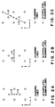
- the standard television signals such as NTSC (National Television System Committee) and Hi-Vision signals are of interlaced signals; that is, as shown in Fig. 1A, one frame is composed of two fields shifted in time and vertical direction.
- the scanning line structure having no time shift is referred to as non-interlaced scanning or progressive scanning.
- the interlaced signals generate flickers when the high frequency components of the video signals increase in the picture vertical direction.
- the scanning lines are interpolated in accordance with a motion-adaptable processing.
- the scanning lines are formed by interpolation on the basis of the vertically adjacent scanning lines on the same field, as shown in Fig. 2A.
- the scanning lines are formed by interpolation on the basis of the scanning lines located at the same positions of two before and after fields different with respect to time, as shown in Fig. 2B.
- the scanning lines are formed by interpolation on the basis of the scanning lines located at different positions of two before and after fields with respect to time, as shown in Fig. 2C.
- the non-interlaced video signals are to be coded. Therefore, when the interlaced video signals are used as the signal sources, it is necessary to first convert the interlaced video signals into non-interlaced video signals.
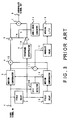
- FIG. 3 A conventional scanning line interpolating apparatus using the motion compensation will be explained hereinbelow with reference to Fig. 3.
- This apparatus is disclosed in "Study of a progressive scanning conversion method for interlaced picture using motion compensation and its apparatus", Institute of Television Engineers of Japan, Technical Report, BCS 93-70.
- interlaced video signals inputted through a video signal input 1 are applied to a field delay circuit 2, a motion compensator 3, and a motion vector (referred to as MV, hereinafter) detector 20, respectively.
- MV motion vector
- the signals are delayed by a period of time corresponding to one field, and the output signals are applied to an intraframe interpolator 9 and a field delay circuit 15.
- the field delay circuit 15 delays the signals by a period of time corresponding to one field in the same way as in the field delay circuit 2, and the output signals are applied to another motion compensator 16.
- the MV detector 20B obtains a motion vector of video signals between two fields, and the obtained values are applied to the two motion compensators 3 and 16.
- the motion compensators 3 and 16 shift the input video signals spatially, and output the shifted video signals.
- the video signals whose motion is compensated as described above are applied from the motion compensators 3 and 16 to an adder 4 and a subtracter 11.
- the adder 4 adds two motion-compensated field signals with two-field difference, and multiplies the added field signals by 1/2 as the interframe interpolation signal.
- the interframe interpolation signal is applied to a multiplier 6.
- the subtracter 11 obtains a difference between the two motion-compensated field signals with two-field difference, and the difference signal is applied to an absolute value converter 17 to obtain an absolute value of the difference signal.
- the absolute difference signal is applied to a spatial LPF (low-pass filter) 19 to smoothen the spacial variation of the absolute difference signal.
- the smoothened absolute difference signal is applied to a non-linear converter 14.
- the non-linear converter 14 converts the output of the space LPF 19 non-linearly into a value "k" indicative of the matching rate between pictures.
- the conversion characteristics are determined as 0 when the output level of the spatial LPF 19 is less than a noise level, and as 1 when the intraframe interpolation level is clearly higher than the interframe interpolation level by an appropriate value. Further, the conversion characteristics are linear between "0" and "1". The value k thus obtained is applied to the multiplier 6 and another multiplier 10.
- the intraframe interpolator 9 adds two video signals on upper and lower scanning lines to be interpolated, as shown in Fig. 2A, to form an intraframe interpolated scanning line.
- the delay generated by the motion compensation can be compensated, and the intraframe interpolation signal is applied to the multiplier 10 in synchronism with the interframe interpolation signal.
- the value k indicative of the matching rate is given from the non-linear converter 14.
- the multiplier 6 multiplies the interframe interpolation signals by (1-k), and the multiplier 10 multiplies the intraframe interpolation signal by k.
- the multiplied results are applied to an adder 7.
- the adder 7 adds the interframe interpolation signal (x (1-k)) and the intraframe interpolation signal (x k) both weighted by the matching rate to obtain final interpolation signal.
- the final interpolation signal is outputted through an interpolation signal output 8.
- a sequential scanning converting apparatus as shown in Fig. 4 is used.
- interpolation signals outputted by a scanning line interpolating apparatus 50 are applied to a line buffer 52.
- the video signals are delayed by a field delay circuit 2 to compensate the processing delay caused by the scanning line interpolating apparatus 50, and then applied to a line buffer 51.
- the two line buffers 51 and 52 hold video signals for one line.
- the video signals held by the buffer 51 or 52 are read at a speed twice higher than the input signals. These read signals are selected alternately through a switch 53 as sequential scanning line signals, and then outputted through a video output 54.
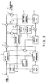
- a motion vector detecting apparatus (which corresponds to the MV detector 20B shown in Fig. 3) for interpolating the motion compensation scanning lines will be explained with reference to Fig. 5.
- interlaced scanning video signals inputted through a video input 1 are applied to a field delay circuit 2, a motion compensator 3, and a temporal MV generator 21.
- the field delay circuit 2 and another field delay circuit 15 delay video signals by one field. Therefore, the video signals delayed by one frame in total are applied to a motion compensator 16.
- the two motion compensators 3 and 16 shift the input video signals spatially, and then output shifted video signals.
- the motion compensating processing is executed in block unit (e.g., 16 x 8 pixels), and the MV is one value in the block.
- the field compensated by the motion compensator 3 and the field compensated by the motion compensator 16 are opposite to each other in time relationship from the interpolated field's point of view, so that the shift directions are opposite to each other as shown in Fig. 2C.
- the video signals thus motion-compensated are applied to a subtracter 11 to obtain interframe difference signals.
- the difference signals are given to an absolute value converter 17.
- the absolute value converter 17 obtains the absolute difference signals (e.g, by squaring the difference signals).
- the obtained absolute difference signals are applied to a block accumulator 24.
- the block accumulator 24 accumulates the absolute difference signals for one block as a value indicative of matching rate, and the obtained value is applied to a MV selector 22. More specifically, the MV values and the matching values between two frames motion-compensated on the basis of the MV values are both inputted to the MV selector 22.
- the MV selector 22 compares the MV values and the matching values to select MV values of the best matching (in which the accumulated value of the difference signals is the minimum). The selected MV values are outputted as the final MV values through an MV output 23.
- the parallel processing may be required at need.
- the interframe interpolation and the intraframe interpolation are switched and further the motion vectors are selected for motion-compensated scanning line interpolation both on the basis of the interframe matching between the fields before and after a field to be interpolated. Therefore, as far as the interframe matching is excellent, the picture in which the interpolation signals are quite different from the upper and lower scanning lines is selected.
- a scanning line interpolating apparatus for appropriately switching inter-picture interpolation to intra-picture interpolation or vice versa, by use of the absolute value of the difference signal between intra-picture interpolation signals and inter-picture interpolation signals passed through a vertical LPF (low-pass filter), in addition to inter-picture matching, and a motion vector detecting apparatus for selecting the motion vectors.
- a vertical LPF low-pass filter
- picture is defined as a frame and also as a field.
- the present invention provides a scanning line interpolating apparatus for, when scanning lines not included in input video signals are formed by interpolation, obtaining interpolation signals by adaptively mixing intra-picture interpolation signals formed on the basis of upper and lower scanning lines spatially apart from scanning lines to be interpolated and inter-picture interpolation signals formed on the basis of before and after pictures different with respect to time from the scanning lines to be interpolated, the scanning line interpolating apparatus comprising: means for obtaining inter-picture matching signals between the before and after pictures different with respect to time and said before and after pictures being used to generate the inter-picture interpolation signals; means for obtaining low frequency component difference signals in a vertical direction of a picture between the intra-picture interpolation signals and the inter-picture interpolation signals; means for obtaining in-and-out matching signals with respect to the intra-picture and inter-picture interpolation signals by obtaining an absolute value of or by squaring the obtained low frequency component difference signals; and means for
- the present invention provides a motion vector detecting apparatus for obtaining motion vectors used for interpolating scanning lines by compensating motions of a plurality of before and after pictures different with respect to time from scanning lines to be interpolated with vector values in a predetermined search area, to select motion vectors on the basis of the compensated results
- the motion vector detecting apparatus comprising: means for obtaining inter-picture interpolation signals by adding the pictures motion-compensated by the vector values; means for obtaining inter-picture matching signals among the pictures motion-compensated by the vector values; means for obtaining intra-picture interpolation signals on the basis of upper and lower scanning lines spatially apart from the scanning line to be interpolated; means for obtaining low frequency component difference signals in a vertical direction of a picture between the intra-picture and inter-picture interpolation signals; means for obtaining in-and-out matching signals with respect to the intra-picture and inter-picture interpolation signals by obtaining an absolute value of or by squaring the obtained low frequency component difference signals; and
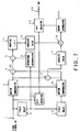
- Fig. 6 is a block diagram showing a preferred embodiment of the scanning line interpolating apparatus according to the present invention.
- the same reference numerals have been retained in Fig. 6 for similar elements which have the same functions as with the case of the conventional apparatus shown in Fig. 3.
- the apparatus shown in Fig. 6 is different from the apparatus shown in Fig. 3 in that a subtracter 5, a vertical LPF (low-pass filter) 12, an absolute value converter 13, and an adder 18 are additionally provided.
- the interpolating method executed by the apparatus shown in Fig. 6 is basically the same as with the case described above. However, the method of determining the criterion for adaptive processing is different from that of the prior art.
- Interlaced video signals are inputted through a video input 1 and then applied to a field delay circuit 2, a motion compensator 3 and an MV detector 20.
- an intraframe interpolator 9 is the same as that of the conventional apparatus, however, the output (the intraframe interpolation signal) is applied to the subtracter 5 in addition to a multiplier 10.
- the processing of an adder 4 is the same as that of the conventional apparatus, however, the output (the interframe interpolation signal) is applied to the subtracter 5 in addition to a multiplier 6.
- the processing of an absolute converter 17 is the same as that of the conventional apparatus, however, the output (the interframe matching signal) is applied to the adder 18.
- the MV detector 20B shown in Fig. 3 can be used as an MV detector 20. However, it is preferable to use an MV detector as shown in Fig. 7 (described later) for improvement of the overall performance.
- the subtracter 5 obtains difference signals between interframe interpolation signals and intraframe interpolation signals obtained as described with reference to Fig. 3.
- the difference signals are applied to the vertical LPF (low-pass filter) 12 for suppressing the high frequency components of the difference signals in the vertical direction.
- the scanning lines two lines above and below the central scanning line are multiplied by 1/8, and the central scanning line and the scanning lines just above and below the central scanning line are multiplied by 1/4.
- the central scanning line and the scanning lines just above and below the central scanning line are multiplied by 1/4.
- the reason why the low frequency components in the vertical direction are used as the in-and-out matching signal (between the intraframe interpolation signals and the interframe interpolation signals) is as follows:
- the frequency components higher than 240 TV-lines cause aliasing in the frame.
- the frequency components mixed with the frequency components lower than 100 TV-lines are those higher than the 380 TV-lines of the original frame, the possibility that these low frequency components exist in the ordinary picture is very low.
- the frequency components lower than 100 TV-lines are different only in phase between the even fields and the odd fields, so that these frequency components are the same in both the fields basically.
- the output of the vertical LPF 12 is converted into an absolute value (or squared), and the obtained in-and-out matching signal is applied to the adder 18.
- the adder 18 adds the in-and-out matching signal (between the intraframe and interframe) to the interframe matching signal.
- the added matching signal is given to the spacial LPF 19.
- the non-linear converter 14 is basically the same as with the conventional one. However, the total conversion gain is reduced by 20 to 30% under consideration that the in-and-out matching signals are added to the interframe matching signals.
- the value k indicative of the matching rate is given from the non-linear converter 14 to the two multipliers 6 and 10.
- the multiplier 6 multiplies the interframe interpolation signals by (1-k).
- the multiplier 10 multiplies the intraframe interpolation signals by k.
- the adder 7 adds the interframe interpolation signals and the intraframe interpolation signals both weighted by the matching rate to mix both appropriately.
- the final interpolation signals are outputted through the interpolation signal output 8.
- a sequential scanning converting apparatus as shown in Fig. 4 is used to form the sequential scanning signals on the basis of the interpolation signals as described above.
- a motion vector detecting apparatus for interpolating the motion-compensated scanning lines will be described with reference to Fig. 7.
- the motion vector detecting apparatus corresponds to the MV detector 20 shown in Fig. 6.
- Fig. 7 is a block diagram showing a preferred embodiment of the motion vector detecting apparatus according to the present invention, to which the deciding method featured in the scanning line interpolating apparatus shown in Fig. 6 is applied.
- FIG. 7 the same reference numerals have been retained for similar elements which have the same functions as with the case of the embodiment as shown in Fig. 6 and the conventional apparatus shown in Fig. 5.
- the apparatus shown in Fig. 7 is different from the apparatus shown in Fig. 4 in that an intraframe interpolator 9, a subtracter 5, a vertical LPF (low-pass filter) 12, an absolute value converter 13 and two adders 4 and 18 are additionally provided.
- the MV detecting method shown in Fig. 7 is basically the same as with the case of the prior art method. However, the method of determining the criterion for the optimum MV is different from the prior art.
- Interlaced video signals are inputted through a video input 1 and then applied to a motion compensator 3, a field delay circuit 2 and a temporal MV generator 21.
- the adder 4 adds the both frame signals to obtain the interframe interpolation signals.
- the obtained signals are applied to the subtracter 5.
- the intraframe interpolator 9 Being the same as that of the interpolating apparatus as shown in Fig. 6, the intraframe interpolator 9 generates the intraframe interpolation signals on the basis of the upper and lower scanning lines of the scanning line to be interpolated. The generated signals are applied to the subtracter 5.
- the subtracter 5 obtains difference signals between the interframe interpolation signals and the intraframe interpolation signals. The obtained difference signals are applied to the vertical LPF 12.
- the operation of the vertical LPF 12 is the same as that shown in Fig. 6. However, since the processing of the motion vector detection is executed in unit of block, the tap is enclosed within the block. This vertical LPF 12 suppresses the higher frequency band about 1/3 of the overall frequency band of the video signals in the vertical direction.
- the output of the vertical LPF 12 is converted into an absolute value (or squared) by the absolute value converter 13, and the obtained in-and-out matching signal is applied to the adder 18.
- the adder 18 adds the in-and-out matching signal and the interframe matching signal, and then the added matching signal is given to a block accumulator 24.
- the operation of the block accumulator 24 and an MV selector 22 are the same as that of the prior art.
- the selected MV is outputted to an MV output 23.
- the apparatuses described as the preferred embodiments process frame video signals. Not only the frame signals, these apparatuses can process field video signals.
- the interpolator 9 is replaced with an inter-field interpolator in Figs. 6 and 7.
- the adder 4, subtractor 11, and absolute value convertor 17 produce an inter-field interpolation signal, inter-field difference signal, and inter-field matching signal, respectively.
- inter-picture (the term "picture” being defined as a frame and also as a field) interpolation signals and intra-picture interpolation signals are switched adaptively or the motion vectors are selected, both by use of the matching signals obtained by passing the absolute difference signals between the intra-picture interpolation signals and the inter-picture interpolation signals through the vertical LPF, in addition to an inter-picture matching signal. Therefore, even if the inter-picture matching is excellent, when the above-mentioned additional matching is not excellent, the interpolation signals and the motion vectors are not selected, with the result that it is possible to markedly reduce the erroneous decision in the adaptive processing and in the vector selection.
- inter-picture interpolation matching processing is executed in all the frequency band, the detection sensitivity is high and the decision is accurate.
Landscapes
- Engineering & Computer Science (AREA)
- Computer Graphics (AREA)
- Multimedia (AREA)
- Signal Processing (AREA)
- Television Systems (AREA)
- Television Signal Processing For Recording (AREA)
- Compression Or Coding Systems Of Tv Signals (AREA)
Claims (2)
- Eine Vorrichtung zum Interpolieren von Abtastzeilen, um, wenn nicht in Eingangsvideosignalen enthaltene Abtastzeilen, durch Interpolation gebildet werden, Interpolationssignale zu erzielen, indem Innenbild-Interpolationssignale, die auf der Basis höherer und niedrigerer Abtastzeilen, die räumlich von zu interpolierenden Abtastzeilen auseinander liegen, gebildet werden, und Zwischenbild-Interpolationssignale, die auf der Basis vorangehender und nachfolgender Bilder gebildet werden, die zu den zu interpolierenden Abtastzeilen zeitbezüglich unterschiedlich sind, adaptiv gemischt werden, wobei die Vorrichtung zum Interpolieren von Abtastzeilen aufweist:eine Einrichtung (11), um Zwischenbild-Übereinstimmungssignale zu erhalten, zwischen vorangehenden und nachfolgenden Bildern, die zeitbezüglich verschieden sind und den vorangehenden und nachfolgenden Bildern, die verwendet werden, um die Zwischenbild-Interpolationssignale zu erzeugen;Einrichtungen (5, 12), um Differenzsignale der niederfrequenten Komponente in einer vertikalen Richtung des Bildes zwischen den Innenbild-Interpolationssignalen und den Zwischenbild-Interpolationssignalen zu erhalten;eine Einrichtung (13), um Übereinstimmungssignale zwischen Ein- und Ausgang bezüglich der Innenbild- und Zwischenbild-Interpolationssignale zu erhalten, durch Erzielen eines Absolutwertes oder durch Quadratur der erhaltenen Differenzsignale der niederfrequenten Komponente; undEinrichtungen (6, 10, 14, 19) zur Änderung eines adaptiven Mischungsverhältnisses aus den Innenbild- und den Zwischenbild-Interpolationssignalen auf der Basis eines Signals, das durch Addition (18) der Zwischenbild-Übereinstimmungssignale und der Übereinstimmungssignale zwischen Ein- und Ausgang erzielt worden ist.
- Eine Bewegungsvektor-Detektionsvorrichtung, um Bewegungsvektoren zu erhalten, die für die Interpolation von Abtastzeilen verwendet werden, indem Bewegungen von mehreren vorausgehenden und nachfolgenden Bildern, die zu Abtastzeilen, die interpoliert werden sollen zeitbezüglich unterschiedlich sind, mit Vektorwerten in einem festgesetzten Suchbereich kompensiert werden, um auf der Basis der kompensierten Ergebnisse Bewegungsvektoren auszuwählen, wobei die Bewegungsvektor-Detektionsvorrichtung aufweist:eine Einrichtung (4), um Zwischenbild-Interpolationssignale durch Addition der durch die Vektorwerte bewegungskompensierten Bilder zu erhalten;eine Einrichtung (11), um Zwischenbild-Übereinstimmungssignale unter den durch die Vektorwerte bewegungskompensierten Bilder zu erhalten;eine Einrichtung (9), um Innenbild-Interpolationssignale auf der Basis höherer und niedrigerer Abtastzeilen zu erhalten, die räumlich von den zu interpolierenden Zeilen auseinander liegen;Einrichtungen (5, 12), um Differenzsignale der niederfrequenten Komponente in einer vertikalen Richtung des Bildes zwischen den Innenbild- und den Zwischenbild-Interpolationssignalen zu erhalten;eine Einrichtung (13), um Übereinstimmungssignale zwischen Ein- und Ausgang bezüglich der Innenbild- und Zwischenbild-Interpolationssignale zu erhalten, durch Erzielen eines Absolutwertes oder durch Quadratur der erhaltenen Differenzsignale der niederfrequenten Komponente;eine Einrichtung (18) zur Addition der Zwischenbild-Interpolationssignale und der Übereinstimmungssignale zwischen Ein- und Ausgang;eine Einrichtung (24) zur Akkumulation der addierten Signale (24); undEinrichtungen (22, 24) zur Auswahl des Vektors mit dem kleinsten akkumulierten Ergebnis als letztendlichen Bewegungsvektor.
Applications Claiming Priority (3)
| Application Number | Priority Date | Filing Date | Title |
|---|---|---|---|
| JP29065094A JP2832927B2 (ja) | 1994-10-31 | 1994-10-31 | 走査線補間装置及び走査線補間用動きベクトル検出装置 |
| JP29065094 | 1994-10-31 | ||
| JP290650/94 | 1994-10-31 |
Publications (3)
| Publication Number | Publication Date |
|---|---|
| EP0710018A2 EP0710018A2 (de) | 1996-05-01 |
| EP0710018A3 EP0710018A3 (de) | 1997-03-26 |
| EP0710018B1 true EP0710018B1 (de) | 1999-07-14 |
Family
ID=17758721
Family Applications (1)
| Application Number | Title | Priority Date | Filing Date |
|---|---|---|---|
| EP19950307761 Expired - Lifetime EP0710018B1 (de) | 1994-10-31 | 1995-10-31 | Vorrichtung zum Interpolieren von Abtastzeilen und Bewegungsvektordetektor |
Country Status (4)
| Country | Link |
|---|---|
| US (1) | US5619273A (de) |
| EP (1) | EP0710018B1 (de) |
| JP (1) | JP2832927B2 (de) |
| DE (1) | DE69510753T2 (de) |
Families Citing this family (26)
| Publication number | Priority date | Publication date | Assignee | Title |
|---|---|---|---|---|
| US5929919A (en) * | 1994-04-05 | 1999-07-27 | U.S. Philips Corporation | Motion-compensated field rate conversion |
| JP3360586B2 (ja) * | 1997-11-21 | 2002-12-24 | 日本電気株式会社 | スキャン変換装置及び方法 |
| JP3164056B2 (ja) | 1998-03-19 | 2001-05-08 | 日本ビクター株式会社 | 動画像符号化復号化装置、動画像符号化復号化方法及び動画像符号記録媒体 |
| US6181382B1 (en) | 1998-04-03 | 2001-01-30 | Miranda Technologies Inc. | HDTV up converter |
| EP1084577A1 (de) * | 1998-04-03 | 2001-03-21 | Miranda Technologies Inc. | Hdtv aufwärtswandler |
| US6118488A (en) * | 1998-08-31 | 2000-09-12 | Silicon Integrated Systems Corporation | Method and apparatus for adaptive edge-based scan line interpolation using 1-D pixel array motion detection |
| JP3821415B2 (ja) | 1998-09-30 | 2006-09-13 | 日本ビクター株式会社 | 動画像フォーマット変換装置及びその方法 |
| JP2000152191A (ja) * | 1998-11-13 | 2000-05-30 | Nec Corp | ノンインターレース画像表示処理装置及び表示処理方法 |
| JP3893227B2 (ja) * | 1999-03-24 | 2007-03-14 | パイオニア株式会社 | 走査線補間装置、及び走査線補間方法 |
| US6545719B1 (en) * | 2000-03-31 | 2003-04-08 | Matsushita Electric Industrial Co., Ltd. | Apparatus and method for concealing interpolation artifacts in a video interlaced to progressive scan converter |
| JP2002044486A (ja) * | 2000-07-19 | 2002-02-08 | Namco Ltd | 情報記憶媒体、画像生成装置、画像生成システム、画像生成方法、及び画像生成プログラム |
| JP2004516718A (ja) * | 2000-12-11 | 2004-06-03 | コーニンクレッカ フィリップス エレクトロニクス エヌ ヴィ | ビデオ信号処理における動き補償型デインターレーシング |
| JP4031390B2 (ja) | 2002-04-17 | 2008-01-09 | 松下電器産業株式会社 | 画像変換装置および画像変換方法 |
| JP4031389B2 (ja) | 2002-04-17 | 2008-01-09 | 松下電器産業株式会社 | 画像変換装置および画像変換方法 |
| US7729563B2 (en) | 2002-08-28 | 2010-06-01 | Fujifilm Corporation | Method and device for video image processing, calculating the similarity between video frames, and acquiring a synthesized frame by synthesizing a plurality of contiguous sampled frames |
| JP3887346B2 (ja) * | 2003-04-28 | 2007-02-28 | 株式会社東芝 | 映像信号処理装置及び映像信号処理方法、映像表示装置 |
| DE602004004672T2 (de) * | 2003-09-04 | 2007-11-15 | Koninklijke Philips Electronics N.V. | Robuste entschachtelung von videosignalen |
| WO2005117446A1 (en) * | 2004-05-25 | 2005-12-08 | Koninklijke Philips Electronics N.V. | Motion estimation in interlaced video images |
| WO2006003545A1 (en) * | 2004-06-30 | 2006-01-12 | Koninklijke Philips Electronics N.V. | Motion estimation with video mode detection |
| CN2804798Y (zh) * | 2005-06-21 | 2006-08-09 | 吴东明 | 一种带磁性装置的水平尺 |
| US20070206117A1 (en) * | 2005-10-17 | 2007-09-06 | Qualcomm Incorporated | Motion and apparatus for spatio-temporal deinterlacing aided by motion compensation for field-based video |
| KR101373896B1 (ko) * | 2006-04-03 | 2014-03-12 | 퀄컴 인코포레이티드 | 전처리기 방법 및 장치 |
| US8472524B2 (en) * | 2006-04-03 | 2013-06-25 | Intel Corporation | Motion compensated frame rate conversion with protection against compensation artifacts |
| US8698954B2 (en) | 2008-03-21 | 2014-04-15 | Nec Corporation | Image processing method, image processing apparatus and image processing program |
| US8736767B2 (en) * | 2010-09-29 | 2014-05-27 | Sharp Laboratories Of America, Inc. | Efficient motion vector field estimation |
| JP6152642B2 (ja) * | 2012-12-28 | 2017-06-28 | 株式会社ニコン | 動画像圧縮装置、動画像復号装置およびプログラム |
Family Cites Families (5)
| Publication number | Priority date | Publication date | Assignee | Title |
|---|---|---|---|---|
| JP2576612B2 (ja) * | 1988-12-28 | 1997-01-29 | 日本ビクター株式会社 | 信号変換装置 |
| GB2246925B (en) * | 1990-08-09 | 1994-04-27 | Sony Broadcast & Communication | Video signal processing |
| GB2249909B (en) * | 1990-11-15 | 1994-09-14 | Sony Broadcast & Communication | Format conversion of digital video signals |
| US5410356A (en) * | 1991-04-19 | 1995-04-25 | Matsushita Electric Industrial Co., Ltd. | Scanning-line interpolation apparatus |
| JP2762794B2 (ja) * | 1991-10-15 | 1998-06-04 | 松下電器産業株式会社 | 走査線補間装置 |
-
1994
- 1994-10-31 JP JP29065094A patent/JP2832927B2/ja not_active Expired - Fee Related
-
1995
- 1995-10-31 DE DE69510753T patent/DE69510753T2/de not_active Expired - Lifetime
- 1995-10-31 US US08/550,625 patent/US5619273A/en not_active Expired - Lifetime
- 1995-10-31 EP EP19950307761 patent/EP0710018B1/de not_active Expired - Lifetime
Also Published As
| Publication number | Publication date |
|---|---|
| DE69510753T2 (de) | 1999-11-11 |
| JP2832927B2 (ja) | 1998-12-09 |
| EP0710018A3 (de) | 1997-03-26 |
| EP0710018A2 (de) | 1996-05-01 |
| DE69510753D1 (de) | 1999-08-19 |
| JPH08130716A (ja) | 1996-05-21 |
| US5619273A (en) | 1997-04-08 |
Similar Documents
| Publication | Publication Date | Title |
|---|---|---|
| EP0710018B1 (de) | Vorrichtung zum Interpolieren von Abtastzeilen und Bewegungsvektordetektor | |
| US5689305A (en) | System for deinterlacing digitally compressed video and method | |
| US7116372B2 (en) | Method and apparatus for deinterlacing | |
| US5488421A (en) | Interlaced-to-progressive scanning converter with a double-smoother and a method therefor | |
| US5943099A (en) | Interlaced-to-progressive conversion apparatus and method using motion and spatial correlation | |
| US4754322A (en) | YC-signal separation circuit responsive to magnitude of vertical correlation | |
| US6509930B1 (en) | Circuit for scan conversion of picture signal using motion compensation | |
| JP2778412B2 (ja) | 動き補償フレーム間コンポジットtv信号直接符号化装置 | |
| US6430316B1 (en) | Motion vector compensation using overlapping weighted windows | |
| EP0883298A2 (de) | Vorrichtung zur Umsetzung von Bildsignalen sowie Fernsehempfänger | |
| KR920004561B1 (ko) | 텔레비젼신호의 움직임 검출회로 | |
| US20130329796A1 (en) | Method and system for motion compensated picture rate up-conversion of digital video using picture boundary processing | |
| EP1592248A1 (de) | Bewegungsvektorschätzung durch adaptive zeitliche Vorhersage | |
| US5412436A (en) | Motion adaptive video processing system | |
| WO1999067952A1 (fr) | Procede et dispositif de conversion de nombre de trames de signaux d'images | |
| JP3201079B2 (ja) | インターレース動画像信号の動き補償予測方法、符号化方法及び装置 | |
| JP3546698B2 (ja) | 走査線補間回路 | |
| GB2277004A (en) | Motion compensated video signal processing; motion/no motion flag | |
| JP3314963B2 (ja) | 画像信号の走査変換装置 | |
| Lee et al. | Video format conversions between HDTV systems | |
| JP2938677B2 (ja) | 動き補償予測方法 | |
| JPH0330586A (ja) | 動き検出回路 | |
| JP3201344B2 (ja) | インターレース動画像信号の動き補償予測方法及び符号化装置 | |
| KR950005648B1 (ko) | 뮤즈 디코더(muse decoder)의 필드간(間) 내삽회로 | |
| JP2002223419A (ja) | 順次走査変換方法および順次走査変換装置 |
Legal Events
| Date | Code | Title | Description |
|---|---|---|---|
| PUAI | Public reference made under article 153(3) epc to a published international application that has entered the european phase |
Free format text: ORIGINAL CODE: 0009012 |
|
| AK | Designated contracting states |
Kind code of ref document: A2 Designated state(s): DE FR GB |
|
| PUAL | Search report despatched |
Free format text: ORIGINAL CODE: 0009013 |
|
| AK | Designated contracting states |
Kind code of ref document: A3 Designated state(s): DE FR GB |
|
| 17P | Request for examination filed |
Effective date: 19970418 |
|
| GRAG | Despatch of communication of intention to grant |
Free format text: ORIGINAL CODE: EPIDOS AGRA |
|
| 17Q | First examination report despatched |
Effective date: 19981112 |
|
| GRAG | Despatch of communication of intention to grant |
Free format text: ORIGINAL CODE: EPIDOS AGRA |
|
| GRAH | Despatch of communication of intention to grant a patent |
Free format text: ORIGINAL CODE: EPIDOS IGRA |
|
| GRAH | Despatch of communication of intention to grant a patent |
Free format text: ORIGINAL CODE: EPIDOS IGRA |
|
| GRAA | (expected) grant |
Free format text: ORIGINAL CODE: 0009210 |
|
| AK | Designated contracting states |
Kind code of ref document: B1 Designated state(s): DE FR GB |
|
| REF | Corresponds to: |
Ref document number: 69510753 Country of ref document: DE Date of ref document: 19990819 |
|
| ET | Fr: translation filed | ||
| PLBE | No opposition filed within time limit |
Free format text: ORIGINAL CODE: 0009261 |
|
| STAA | Information on the status of an ep patent application or granted ep patent |
Free format text: STATUS: NO OPPOSITION FILED WITHIN TIME LIMIT |
|
| 26N | No opposition filed | ||
| REG | Reference to a national code |
Ref country code: GB Ref legal event code: IF02 |
|
| REG | Reference to a national code |
Ref country code: DE Ref legal event code: R082 Ref document number: 69510753 Country of ref document: DE Representative=s name: 2K PATENTANWAELTE BLASBERG KEWITZ & REICHEL, P, DE |
|
| REG | Reference to a national code |
Ref country code: DE Ref legal event code: R082 Ref document number: 69510753 Country of ref document: DE Representative=s name: 2K PATENTANWAELTE BLASBERG KEWITZ & REICHEL, P, DE Effective date: 20120430 Ref country code: DE Ref legal event code: R082 Ref document number: 69510753 Country of ref document: DE Representative=s name: 2K PATENTANWAELTE BLASBERG KEWITZ & REICHEL PA, DE Effective date: 20120430 Ref country code: DE Ref legal event code: R081 Ref document number: 69510753 Country of ref document: DE Owner name: JVC KENWOOD CORPORATION, JP Free format text: FORMER OWNER: VICTOR COMPANY OF JAPAN, LTD., YOKOHAMA, JP Effective date: 20120430 Ref country code: DE Ref legal event code: R081 Ref document number: 69510753 Country of ref document: DE Owner name: JVC KENWOOD CORPORATION, YOKOHAMA-SHI, JP Free format text: FORMER OWNER: VICTOR COMPANY OF JAPAN, LTD., YOKOHAMA, KANAGAWA, JP Effective date: 20120430 |
|
| REG | Reference to a national code |
Ref country code: FR Ref legal event code: TP Owner name: JVC KENWOOD CORPORATION, JP Effective date: 20120705 |
|
| PGFP | Annual fee paid to national office [announced via postgrant information from national office to epo] |
Ref country code: GB Payment date: 20131030 Year of fee payment: 19 Ref country code: FR Payment date: 20131009 Year of fee payment: 19 Ref country code: DE Payment date: 20131023 Year of fee payment: 19 |
|
| REG | Reference to a national code |
Ref country code: DE Ref legal event code: R119 Ref document number: 69510753 Country of ref document: DE |
|
| GBPC | Gb: european patent ceased through non-payment of renewal fee |
Effective date: 20141031 |
|
| PG25 | Lapsed in a contracting state [announced via postgrant information from national office to epo] |
Ref country code: DE Free format text: LAPSE BECAUSE OF NON-PAYMENT OF DUE FEES Effective date: 20150501 Ref country code: GB Free format text: LAPSE BECAUSE OF NON-PAYMENT OF DUE FEES Effective date: 20141031 |
|
| REG | Reference to a national code |
Ref country code: FR Ref legal event code: ST Effective date: 20150630 |
|
| PG25 | Lapsed in a contracting state [announced via postgrant information from national office to epo] |
Ref country code: FR Free format text: LAPSE BECAUSE OF NON-PAYMENT OF DUE FEES Effective date: 20141031 |