EP0709983B1 - Méthode et dispositif d'allocation pour la réutilisation des ressources de réseau dans un système de communication sans fils - Google Patents
Méthode et dispositif d'allocation pour la réutilisation des ressources de réseau dans un système de communication sans fils Download PDFInfo
- Publication number
- EP0709983B1 EP0709983B1 EP94480114A EP94480114A EP0709983B1 EP 0709983 B1 EP0709983 B1 EP 0709983B1 EP 94480114 A EP94480114 A EP 94480114A EP 94480114 A EP94480114 A EP 94480114A EP 0709983 B1 EP0709983 B1 EP 0709983B1
- Authority
- EP
- European Patent Office
- Prior art keywords
- base station
- base stations
- stations
- base
- network
- Prior art date
- Legal status (The legal status is an assumption and is not a legal conclusion. Google has not performed a legal analysis and makes no representation as to the accuracy of the status listed.)
- Expired - Lifetime
Links
- 238000000034 method Methods 0.000 title claims description 72
- 238000004891 communication Methods 0.000 title claims description 41
- 230000006854 communication Effects 0.000 title claims description 41
- 230000004044 response Effects 0.000 claims description 11
- 238000012544 monitoring process Methods 0.000 claims description 6
- 230000007175 bidirectional communication Effects 0.000 claims description 2
- 230000002457 bidirectional effect Effects 0.000 claims 1
- 230000008569 process Effects 0.000 description 23
- 238000010586 diagram Methods 0.000 description 11
- 230000005540 biological transmission Effects 0.000 description 9
- 238000007726 management method Methods 0.000 description 9
- 238000001228 spectrum Methods 0.000 description 9
- 235000008694 Humulus lupulus Nutrition 0.000 description 7
- 230000006870 function Effects 0.000 description 7
- 230000011664 signaling Effects 0.000 description 5
- 238000013500 data storage Methods 0.000 description 4
- 238000013461 design Methods 0.000 description 4
- 238000012545 processing Methods 0.000 description 4
- 101100172132 Mus musculus Eif3a gene Proteins 0.000 description 3
- 230000008859 change Effects 0.000 description 3
- 238000009434 installation Methods 0.000 description 3
- 125000004122 cyclic group Chemical group 0.000 description 2
- 238000009432 framing Methods 0.000 description 2
- 101150101590 hop-1 gene Proteins 0.000 description 2
- 238000012423 maintenance Methods 0.000 description 2
- 238000012986 modification Methods 0.000 description 2
- 230000004048 modification Effects 0.000 description 2
- 230000003068 static effect Effects 0.000 description 2
- 230000003044 adaptive effect Effects 0.000 description 1
- 238000013459 approach Methods 0.000 description 1
- 230000003190 augmentative effect Effects 0.000 description 1
- 230000008901 benefit Effects 0.000 description 1
- 230000001419 dependent effect Effects 0.000 description 1
- 238000001514 detection method Methods 0.000 description 1
- 230000000694 effects Effects 0.000 description 1
- 238000005562 fading Methods 0.000 description 1
- 230000000977 initiatory effect Effects 0.000 description 1
- 238000005259 measurement Methods 0.000 description 1
- 230000007246 mechanism Effects 0.000 description 1
- 238000010295 mobile communication Methods 0.000 description 1
- 230000000737 periodic effect Effects 0.000 description 1
- 238000000926 separation method Methods 0.000 description 1
- 230000001360 synchronised effect Effects 0.000 description 1
Images


Classifications
-
- H—ELECTRICITY
- H04—ELECTRIC COMMUNICATION TECHNIQUE
- H04W—WIRELESS COMMUNICATION NETWORKS
- H04W28/00—Network traffic management; Network resource management
- H04W28/16—Central resource management; Negotiation of resources or communication parameters, e.g. negotiating bandwidth or QoS [Quality of Service]
- H04W28/26—Resource reservation
-
- H—ELECTRICITY
- H04—ELECTRIC COMMUNICATION TECHNIQUE
- H04B—TRANSMISSION
- H04B1/00—Details of transmission systems, not covered by a single one of groups H04B3/00 - H04B13/00; Details of transmission systems not characterised by the medium used for transmission
- H04B1/69—Spread spectrum techniques
- H04B1/713—Spread spectrum techniques using frequency hopping
- H04B1/715—Interference-related aspects
- H04B2001/7152—Interference-related aspects with means for suppressing interference
-
- H—ELECTRICITY
- H04—ELECTRIC COMMUNICATION TECHNIQUE
- H04W—WIRELESS COMMUNICATION NETWORKS
- H04W16/00—Network planning, e.g. coverage or traffic planning tools; Network deployment, e.g. resource partitioning or cells structures
- H04W16/02—Resource partitioning among network components, e.g. reuse partitioning
- H04W16/12—Fixed resource partitioning
-
- H—ELECTRICITY
- H04—ELECTRIC COMMUNICATION TECHNIQUE
- H04W—WIRELESS COMMUNICATION NETWORKS
- H04W28/00—Network traffic management; Network resource management
- H04W28/16—Central resource management; Negotiation of resources or communication parameters, e.g. negotiating bandwidth or QoS [Quality of Service]
-
- H—ELECTRICITY
- H04—ELECTRIC COMMUNICATION TECHNIQUE
- H04W—WIRELESS COMMUNICATION NETWORKS
- H04W60/00—Affiliation to network, e.g. registration; Terminating affiliation with the network, e.g. de-registration
-
- H—ELECTRICITY
- H04—ELECTRIC COMMUNICATION TECHNIQUE
- H04W—WIRELESS COMMUNICATION NETWORKS
- H04W64/00—Locating users or terminals or network equipment for network management purposes, e.g. mobility management
- H04W64/006—Locating users or terminals or network equipment for network management purposes, e.g. mobility management with additional information processing, e.g. for direction or speed determination
-
- H—ELECTRICITY
- H04—ELECTRIC COMMUNICATION TECHNIQUE
- H04W—WIRELESS COMMUNICATION NETWORKS
- H04W72/00—Local resource management
-
- H—ELECTRICITY
- H04—ELECTRIC COMMUNICATION TECHNIQUE
- H04W—WIRELESS COMMUNICATION NETWORKS
- H04W84/00—Network topologies
- H04W84/02—Hierarchically pre-organised networks, e.g. paging networks, cellular networks, WLAN [Wireless Local Area Network] or WLL [Wireless Local Loop]
- H04W84/10—Small scale networks; Flat hierarchical networks
- H04W84/12—WLAN [Wireless Local Area Networks]
-
- H—ELECTRICITY
- H04—ELECTRIC COMMUNICATION TECHNIQUE
- H04W—WIRELESS COMMUNICATION NETWORKS
- H04W88/00—Devices specially adapted for wireless communication networks, e.g. terminals, base stations or access point devices
- H04W88/02—Terminal devices
- H04W88/04—Terminal devices adapted for relaying to or from another terminal or user
-
- H—ELECTRICITY
- H04—ELECTRIC COMMUNICATION TECHNIQUE
- H04W—WIRELESS COMMUNICATION NETWORKS
- H04W88/00—Devices specially adapted for wireless communication networks, e.g. terminals, base stations or access point devices
- H04W88/08—Access point devices
Definitions
- This invention relates generally to communications systems and, in particular such communications in a wireless local area network (LAN). Specifically, the invention is directed to assignment of network resources in communication systems using shared multiple access communication media, such as, for instance, frequency hopping patterns, in a multicell radio LAN based on slow frequency hopping spread spectrum signaling.
- shared multiple access communication media such as, for instance, frequency hopping patterns
- a typical wireless LAN topology is divided into cells. Associated with each cell is a base station connected to a backbone network which acts as an access point and relay for remote stations. To become part of the network, remote stations have to register with one of the base stations. All communications between the remote station and other entities are subsequently handled by the base station with which the remote station has registered.
- a multicell radio LAN installation based on slow frequency hopping spread spectrum signaling may consist of a set of base stations with overlapping coverage areas.
- FH frequency hopping
- the period of constant frequency is called a hop and messages may be exchanged during these hops.
- Efficient methods for controlling and minimizing radio interference between overlapping cells are essential to the reliability and performance of such radio LAN installations.
- the transmission and reception of messages in a cell of a multicell network of the type that employs identical communication frequencies in different cells requires control of interference between users. This interference may occur from several sources including transmission from remote stations that lie in overlapping areas between adjacent cells and transmissions from base stations if these overlapping cell areas contain one or more remote users. Assigning different frequency hopping sequences or patterns to base stations with overlapping coverage areas allows to control and limit interferences.
- US patent N' 5.239.673 teaches a scheduling method for efficient frequency reuse in a multi-cell wireless network served by a wired local area network.
- One method of the invention circulates a high priority token among a plurality of header stations connected to the wired network. Reception of the token causes the receiving header station to perform wireless communications. When finished, the header station forwards the token to another header station.
- U.S. Patents show communication systems having overlapping coverage areas: U.S. Patent 4,597,105, June 24, 1986, entitled “Data Communications System having Overlapping Receiver coverage Zones” to Freeburg and U.S. Patent 4,881,271 issued November 14, 1989, entitled “Portable Wireless Communication Systems” to Yamauchi et al. provide for a hand-off of a subscriber station from one base station to another by the base station continually monitoring the signal strength of the subscriber station.
- F. Gfeller et al. describe an infrared communication system that operates between a plurality of satellite stations and a plurality of terminal stations.
- a host computer communicates with the terminal stations via a cluster controller and the satellite stations, which may be ceiling mounted. Communication with the terminal stations is not interrupted even during movement of the terminal stations.
- Gfeller describes general control principles of an infrared wireless network incorporating multiple ceiling mounted transponders that couple a host/controller to multiple terminal stations. Access to the uplink channel is controlled by a Carrier Sense Multiple Access/Collision Detection (CSMA/CD) method.
- CSMA/CD Carrier Sense Multiple Access/Collision Detection
- the invention as defined is to provide a method for reusing a limited number of network resources in a communication system using a multiple access shared communication medium such as a wireless radio frequency (RF) or infrared (IR) communication network comprised of a local area network connected to a plurality of base stations.
- RF radio frequency
- IR infrared
- Each base station has a geographic area, defined as a cell, within which remote stations are within reception range.
- Remote stations select one base station as home base station.
- Home base stations are capable of performing bidirectional communication with one or more remote stations under control of a controller connected to said local area network, the method of the invention comprises the steps of:
- This method allows to select and assign one of the network resources already assigned to one or more other base stations. Selection is based on the computation by the controller of a distance index between the given base station and the other base stations.
- the resource assigned to the given base station is the one already assigned to one of the other base stations with the highest distance index to the given base station.
- this method is particularly suited to reuse frequency hopping patterns when the number of active base stations exceeds the number of available frequency hopping patterns. Assigning a frequency hopping pattern already in use by a base station with the highest distance index reduces the risk of interference between two base stations using the same frequency hopping pattern.
- Another aspect of the invention is to compute distance index based on data representative of base stations cells overlaps. Such cells overlap occurs at locations where a remote station is within RF or IR reception range of several active base stations. Cells overlaps information is used by the controller to reuse a network resource to assign it to a requesting base station.
- the method used to compute a distance index between the requesting base station and the other active base stations comprises the following steps:
- the computing system typically includes a Wireless Network Controller (WNC) 18, with attached monitor 20 and keyboard 22, of a local area network (LAN), generally indicated by reference numeral 24, having a plurality of attached workstations or personal computers (not shown for simplicity).
- WNC Wireless Network Controller
- LAN local area network
- gateways 26 and 28 are attached to the LAN.
- These gateways are augmented according to the invention to provide certain radio system management functions which coordinate the remote stations' access to the common radio channel. Communications between remote stations is supported via relay through the base stations 26 and 28.
- a base station 26 or 28 which may be a conventional microcomputer, has a LAN adapter 30 inserted in a bus slot and connected to LAN cabling 32.
- the WNC typically also a conventional microcomputer and including one or more direct access storage devices (DASDs) such as hard disks (not shown), also has a LAN adapter 34 inserted in a bus slot and connected to LAN cabling 32.
- the LAN adapters 30 and 34 and the LAN cabling 32 together with LAN software constitute the LAN 24.
- the LAN 24 is of conventional design and does not form part of the invention.
- the base station 26 or 28 also has an RF transceiver adapter 36 implemented as a printed circuit card which is inserted in a bus slot of the base station.
- the transceiver adapter 36 includes a spread spectrum transceiver of conventional design.
- the transceiver adapter 36 has an antenna 38 by which a radio link 40 is established with one or more remote stations, 10, 12, 14, or 16.
- the remote station may itself be a hand held or lap top computer of conventional design and, like the base station, it is provided with an antenna 42 and a transceiver adapter 44, which may also be implemented as a printed circuit card which is inserted in a bus slot of the computer.
- the transceiver adapter 44 like transceiver adapter 36, includes a spread spectrum transceiver of similar design.
- the base station and the remote stations are further provided with software, generally indicated by reference numerals 46 and 48, respectively, which support their respective transceiver adapters.
- FIG. 2 shows the radio system common to both the remote stations and the base stations of FIG. 1.
- the radio system includes a transceiver adapter 36 or 44 connected to the computer 50 via the computer's bus interface 52.
- the transceiver section is itself divided into an RF transceiver 54, which may be a commercially available spread spectrum transceiver, and a dedicated microprocessor system 56 which controls the transceiver via an interface 58.
- the microprocessor system 56 further includes a system interface 60 which interfaces the transceiver section to the computer section 50.
- the microprocessor system includes a dedicated microprocessor 62 containing high-resolution time interval determination hardware or "timers" typical of real-time microprocessor systems.
- Microprocessor 62 is connected by a memory bus 64 to program storage 66 and data storage 68 as well as to interfaces 60 and 58 providing attachment to bus interface 52 and RF transceiver 54, respectively.
- Program storage 66 is typically read only memory (ROM), while data storage 68 is static or dynamic random access memory (SRAM or DRAM). Packets received or to be sent are held in data storage 68 and communicated to or from the RF transceiver 54 via interface 58 under control of serial channels and a direct memory access (DMA) controller (not shown) which is part of the microprocessor 62.
- DMA direct memory access
- serial channels The function of these serial channels is to encapsulate data and control information in an HDLC (high-level data link control) packet structure and provide the packet in serial form to the RF transceiver 54.
- HDLC high-level data link control
- the serial channels check the packet destination address, check for errors, and deserialize the packet to data storage 68.
- the serial channels must have the capability to recognize a specific adaptor address as well as a broadcast address.
- Specific microprocessors with appropriate serial channel and timer facilities include the Motorola 68302 and the National HPC46400E microprocessors.
- the computer 50 runs an operating system 70 which supports one or more user application programs 72.
- Operating system 70 may include a communications manager 74, or the communications manager 74 may itself be an application program installed on the computer. In either case, the communications manager 74 controls a device driver 76 via the operating system 70.
- the device driver 76 communicates with the transceiver adapter 36 or 44 via bus interface 52.
- FIG. 3 shows one protocol which may be used in the preferred embodiment of the invention. It is to be appreciated that other protocols may be utilized in the practice of the invention. While the protocol is equally applicable to radio frequency (RF), infrared (IR), or wired transmission systems with broadcast capability, and to either conventional or spread-spectrum modulation techniques, slow-frequency hopped spread spectrum radio systems have a natural affinity for the protocol since those systems share a structure to time with the protocol. With reference to FIG. 3, there are five intervals defining a "hop". The first (and last) interval, G, is the interval during which the transmitter carrier frequency is changing. Note that the G interval is needed only for frequency hopping systems.
- This interval, X1 is the interval during which the base station broadcasts a special message to all the remote stations identifying the beginning of the following, or B, interval.
- the B interval is the interval during which, by convention, only the base station may initiate transmission and remote stations may respond only when required by the message protocol. For example, the remote station may acknowledge a message outbound from the base or may respond when polled.
- the B interval has a duration T1.
- the B interval is followed, in turn, by the X2 interval which is the interval during which the base station broadcasts a special message to all the remote stations identifying the end of the B interval and, by implication, the beginning of the C interval.
- the message also conveys the length of the C interval and, optionally, the length of the B interval as well.
- the X2 broadcast message is not strictly necessary. Information about the entire hop structure can be conveyed in the X1 interval.
- the X2 message is included to support operation of simplified remote stations capable of only contention-mode operation. These stations wait for the X2 message and contend subsequently.
- the C interval is the interval during which any station, including (or optionally excluding) the base station, may contend for the channel and transmit a message without the consent of the base station. For example, a CSMA/CA (carrier sense multiple access with collision avoidance) protocol may be used in this interval.
- the C interval duration is T2. If a remote station sends a message and receives an acknowledgement, it can assume the message has been received correctly. If not, it will contend again.
- Tmsg is the time to transmit a particular message and Tack is the time to transmit an acknowledgement and Turnaround is the time between the end of a transmission of a message and the initiation of the transmission of an acknowledgement
- Tmsg + Tack + Turnaround is the time between the end of a transmission of a message and the initiation of the transmission of an acknowledgement
- the base station can expand or contract the contention interval. If the system is very lightly loaded and most of the traffic is inbound to the base station, it is advantageous to remote response time to lengthen the time period T2. Conversely, if the system is heavily loaded and most of the traffic is outbound, the time period T2 should be minimized. The time period T2 should not be reduced to zero, however, as it is the only mechanism by which a newly activated remote station can register itself to the base station. Additionally, a further subdivision of the B interval, in which remote-to-base traffic is carried in allocated times lots, may be made as shown in FIG. 3A. In FIG.
- the B interval is subdivided into B1 and B2 subintervals, and the B2 subinterval is, in turn, subdivided into a plurality of time slots, each time slot being allocated to a specific remote station.
- Requests for an allocated slot may be made by a remote station in response to a poll during the B1 subinterval, or the requests may be made during the C interval.
- slot allocation guarantees that the remote station can transmit to the base station during its allocated time slot.
- the boundary between the B2 subinterval and the C interval By varying the boundary between the B2 subinterval and the C interval, the suitability of the system to different types of traffic can be adjusted. As the traffic load for steady, predictable traffic (e.g., real-time audio and video) increases, the boundary can be moved to lengthen the B2 subinterval and shorten the C interval, thereby increasing the number of allocatable time slots. Conversely, as the traffic becomes less predictable, the boundary can be moved to lengthen the C interval, providing greater bandwidth for contention-based traffic.
- predictable traffic e.g., real-time audio and video
- the "hop" is divided into two subdivisions, one of which supports a controlled access scheme and the other of which supports a random access scheme.
- the invention may operate in any one of three modes: one in which only the X1 message is sent, one in which only the X2 message is sent, and one in which both are sent.
- the X1 message constitutes the header section of a frame. It identifies the start of the information frame, carries a unique identification of the base station, identifies the frequency hopping pattern, and defines the length of the B and C intervals.
- the X1 message also carries general broadcasting and system control information.
- each remote station waits for the X1 message.
- a remote station sets an internal timer for T1 and for T1 + T2 so that it knows when the contention interval begins and when to schedule its next frequency change. Broadcast reception of messages is not guaranteed, only likely. Radio conditions may be such that a particular remote station does not hear the broadcast message X1. Because a remote station cannot transmit autonomously without first hearing the X1 message and letting T1 elapse, it will remain quiet for the entire frame. Alternatively, if the remote station is polled by the base station during interval B, it may respond, but in no case can it contend in the C interval.
- Each frame time period of length T T1 + T2 can also be a frequency hopping period for implementation under FCC regulation part 15.
- a fixed length of time T is recommended but not necessary.
- a fixed length of time T is especially useful in the following cases:
- a large time T makes the system overhead smaller, and a small time T makes the system response time smaller.
- the system can transmit the X2 message only.
- the content of the X2 message can be similar to that of the X1 message except that remote stations receiving the X2 message can immediately begin contention. This may be an advantage in some applications.
- For the case of transmitting the X2 message only suppose the base station polls a remote station near the end of the B interval, and the remote station responds with a lengthy message. Generally, the protocol must prohibit these responses from being too lengthy. It may be that the response is active even as the period T1 expires.
- both X1 and X2 messages can be used to simplify the implementation of the remote station and to provide redundancy.
- the X1 message would then signal the beginning of the B interval, and the X2 message would signal the beginning of the C interval.
- interference control includes methods for accomplishing the following key steps in such a system.
- wireless cells are grouped into logical LANs, each logical LAN being controlled by a Wireless Network Controller 18 in Fig. 1A (WNC).
- the FH component of the Wireless Network Controller performs FH pattern management and control functions in a Logical LAN, for that purpose it is in communication with a wireless control agent (WCA) located in each base station.
- WCA wireless control agent
- Each distinct Logical LAN is considered an autonomous network and carries a unique network identifier (NETWORK-ID).
- NETWORK-ID unique network identifier
- each logical LAN includes a WNC and one or more Wireless Control Agents (WCA). Where the WNC and WCAs are physically situated, is a function of the type of the system.
- WNC and WCAs are physically situated, is a function of the type of the system.
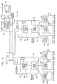
- a base station 82 includes both a WNC 84 and a WCA 88.
- the WNC is connected to a monitor 86 and the WCA 88.
- the WNC 84 and WCA 88 are together responsible for the distribution and maintenance of hopping patterns.
- the WNC 84 is a centralized managing station operating in a specified station, in this instance, base station 82.
- the WCA 88 is located in every base station in a logical LAN. In this instance since there is only one base station 82, it is in the same station as the WNC 84. As discussed below, this is not so in a multiple cell network.
- the WCA 88 is connected to a wireless adapter 90, which includes a radio control transceiver 92 for communicating with a plurality of remote stations.
- a remote station 94 includes a radio control transceiver 96 for communicating with radio control transceiver 92 in the wireless adapter 90 of base station 82.
- Remote stations 98 and 102 communicate in a like manner via radio control transceivers 100 and 104, respectively.
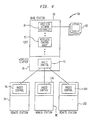
- FIG. 5 illustrates a multiple cell network 106 in which the WNC and WCA are in different physical units.
- the WNC is a centralized managing entity operating in a specific station.
- the WNC may be in any terminal or station on a backbone LAN, whether it is a base station or not.
- For multi-segment LANs there is a unique WNC for the whole network. This is true even for heterogeneous LANs including for instance token-ring and Ethernet segments as long as the network identifier is unique.
- the WCA is located in each base station linked to a backbone LAN, and acts as a representative of the WNC.
- the WCA functions as a cell controller and is responsible for opening the base station adapter for communication.
- the multiple cell network 106 of FIG. 5 includes a network station 108 which includes the WNC 110 which communicates with a monitor 112 and a backbone adapter 114 which is connected to a backbone LAN 116.
- the WNC 110 has access to a network control database 109 comprising network topology and frequency management information. It is seen that the network station 108 does not include a WCA.
- a plurality of base stations, each of which includes a WCA, is connected to the LAN 116. For example, base stations 118 and 120 are connected to the LAN 116. When two base stations have overlapping geographical coverage areas they are called neighbors.
- Base station 118 includes a WCA 122 which communicates with the WNC 110 of network station 108 via LAN 116, and with wireless adapter 124 which includes a radio control transceiver 126.
- the transceiver 126 communicates with a plurality of remote stations 128, 132 and 136 which include radio control transceivers 130, 134 and 138, respectively.
- Base station 120 includes a WCA 138 which communicates with the WNC 110 of network station 108 via LAN 116, and with wireless adapter 140 which includes a radio control transceiver 142.
- the transceiver 142 communicates with a plurality of remote stations 144, 148 and 152 which include radio control transceivers 146, 150 and 154, respectively.
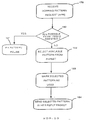
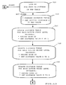
- FIG. 6 is a flow chart which provides an overview of Frequency Hopping operation in a single Logical LAN.
- a base station When a base station is powered on at block 160 it must first acquire a FH pattern to use in the cell as shown at block 162. This is accomplished by sending a request and then receiving a FH pattern in response from the Wireless Network Controller.
- the base monitors its radio environment at block 164 to ensure that no other base within its radio vicinity is using the same FH pattern. Then it starts frequency hopping at block 166. It also communicates the FH pattern to remote stations within its range. Remote stations perform monitoring of interference on the hops in a FH pattern.
- the base station monitors interference on the FH pattern at block 168.
- FIG. 7 illustrates a superframe comprised of M Hops. There are M used hops at any given time, and N-M unused hops, where M is an integer which is less than the total number of available hopping frequencies N (M ⁇ N). How a hopping pattern is acquired by a base station is explained below.
- FIG. 8 illustrates an example of a frequency band (83 MHZ wide) divided into 83 available channels each 1 MHZ wide. A subset of the channels can be chosen to form a FH pattern. Each hop is one megahertz (1 MHZ) wide, and the frequencies entered from 2.400 gigahertz (GHZ) to 2.482 (GHZ). It is to be appreciated that a different frequency band may be utilized in the practice of the invention. In practice, different countries have different rules governing the frequency bands that may be utilized. As is known in the art, data is modulated on the carrier frequencies (hopping frequencies) for transmission between base stations and remote stations.
- a requesting base station When a requesting base station is powered on, it sends a Hopping Pattern Request (HPR) packet to the Wireless Network Controller.
- HPR Hopping Pattern Request
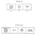
- Fig. 9 shows the structure of a HPR packet the first field carries a predetermined code indicating that it is a frequency hopping pattern request, the next field carries the identifier assigned to the base station requesting a FH pattern and the last field carries the identifier of the logical network the requesting base station wants to register in.
- the Wireless Network Controller on receipt of a Hopping Pattern Request packet, executes the following steps as shown in FIG. 10. A determination is made at block 180 if all FH patterns from the set of possible patterns have already been assigned to active base stations belonging to the same logical network as the requesting base station. If so the process jumps to block 181 to reuse a FH pattern according to a method further explained below in relation with Fig 13. If not, the process randomly selects a FH pattern from the set (FHPSET) of patterns at block 182 among those which have not been assigned. The Wireless Network Controller keeps track of FH patterns that are being used by the base stations belonging to the logical network it controls as shown in block 183. At block 184 the process communicates to the base station the resulting FH pattern.
- the FH pattern information is contained in response to a hopping pattern request (HPR) message as shown in Fig. 11, the first field carries a predetermined code indicating that it is response to a hopping pattern request, the next field carries the identifier of the Wireless Network Manager answering the hopping pattern request and the last field carries the FH pattern assigned to the requesting base station.
- HPR hopping pattern request
- the requesting base station On receipt of the message, the requesting base station immediately starts hopping with its newly assigned FH pattern.
- the same steps (176 to 184, Fig. 10) are performed upon request from a base station which detects that another base is using the same FH pattern as shown in step 164 Fig. 6.
- One object of the invention is to provide a method for reusing frequency hopping patterns when all possible patterns have already been assigned to active base stations as will be describe in detail in reference to Figure 13. Such a method involves information gathered by the Wireless Network Controller 110 (Fig. 5) in the centralized network control data base 109 whose structure is going to be described hereafter.
- the network resident data table 210 (Fig. 12) holds the network attributes common to all the stations of a given logical LAN.
- the NETWORK_ID parameter identifies a given logical wireless LAN among other collocated logical LANs.
- the country code identifies the nation in which the system operates and is necessary to conform with the regulations set in each country to control the operation of mobile systems and more particularly RF systems. Some kind of security key information is also necessary to prevent that unauthorized users may join the network or monitor the data traffic. Other network options such as access control type also has to be stored in the network resident data table and shared with all the stations.
- Frequency management information is provided in the frequency hopping patterns table 250.
- the frequency hopping patterns table 250 lists all the frequency hopping patterns available in the country where the system operates.
- frequency hopping pattern FHPk consists in the sequence of M frequencies f(k,1) ...f(k,M) which is a unique sequence of the M used frequencies HOP1 ... HOPM.
- Each entry in the frequency hopping patterns table comprises a first field carrying frequency hopping patterns identifiers (FHP1 to FHP78) followed by the sequence of M frequencies constituting the frequency hopping pattern, for instance f(k,1) to f(k,M) is the sequence corresponding to FHPk.
- Each entry also comprise an additional field (not shown in Fig. 12) indicating whether the corresponding FH pattern is assigned to an active base station, this information is used by the network controller when looking for a free FH pattern at step 10 of Fig. 10. These patterns are not static, they are updated each time a new interference situation is faced and the new information is automatically provided to all the active base stations of the logical wireless LAN network. If single frequency channels are used, the frequency management information would consist in a list of frequencies. If direct sequence spread spectrum is used the frequency management information contains the list of all available chip codes.
- the network topology directory table 230 lists all the base stations which form the logical LAN and carries a list of parameters assigned to each base station. It also keeps track of information representative of the radio topology of the wireless LAN system and more specifically it holds a list of direct neighbor base stations for each base station belonging to the logical wireless LAN. There is one entry for each base station defined in the logical wireless LAN system, each entry comprises:
- a base station In order to be allowed to register in a given logical wireless LAN system, a base station must be defined in the network topology directory 230 with its network address on the LAN backbone. This is defined by the network operator at network set-up time. At network set-up time, the network operator also provides for each base station the list of other neighboring base stations, based on the physical set-up of the system and taking into account interference measurements performed as part of the network planning and installation procedure. Defining a new base adds an entry in the network topology directory.
- the base station requests its operating parameters from the wireless network controller 110 through the LAN backbone 116.
- the operating parameters include the network identifier (NETWORK_ID), the country code, the network options, the base station identifier (BASE_ID), the frequency hopping pattern assigned to the base station (CELL_FHP) and the base station emitted power.
- the network identifier, the country code, the network options and the base station emitted power are those provided at network set-up time by the operator.
- the base station identifier and the frequency hopping pattern may be assigned in different manners.
- a first approach is to simply keep track of the base station identifiers and frequency hopping patterns that have been already assigned and to select randomly among those which are still available. Such a method limits the number of base stations in a given wireless LAN system to the maximum number of base station identifiers or to the maximum number of frequency hopping patterns available in the country where the system operates.
- the maximum number of base stations identifiers is 64 and the maximum number of frequency hopping patterns vary from around 60 to 80 depending on the various country regulations.
- One object of this invention is to overcome these limits by reusing already assigned frequency hopping patterns.
- the method of the invention uses information about neighboring stations from the network topology database to derive an indication of radio cell distance between the various base stations as described in detail below.
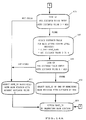
- step 310 the wireless network controller looks-up in the frequency hopping patterns table 250 for a free FH pattern. If it finds one the process jumps directly to step 360 Fig.13A as shown by connector B and the available FH pattern is returned to the requesting base station.
- a distance table with a first column consisting in the list of all existing FH patterns identifiers (FHP1 to FHP78), a second column for storing the identifier of the base station using the FH pattern of the first column and a third column for storing an integer value D representative of the distance between the requesting base station and the base station of the second column.
- the initial value of D is set to a maximum value MAX for all entries of the distance table.
- the process looks up in the network topology table 230 for the entry corresponding to the requesting base station identified by its BASE_ID. Based on the list of neighbor base stations and the direct access index of the corresponding entry in the network topology table the process retrieves the assigned FH pattern and the status of each neighbor base station. For those neighbor base stations whose status is active, the process updates the entry in the distance table corresponding to their assigned FH with the neighbor base station identifier BASE_ID and sets the value D of the corresponding distance to 1. As a result of step 320, all the direct neighbors of the requesting base station are included in the distance table and the value of the distance D between the requesting base station and its direct neighbors is set to 1.
- Step 325 is similar to step 320, the process updates distance table entries corresponding to FH patterns assigned to those second level neighbors whose status is active.
- Second level neighbors are direct neighbors of the requesting base station's direct neighbors. Each entry carries the FH pattern assigned to the corresponding second level neighbor and the second level neighbor base station identifier. For these entries, the value of the distance D is set to 2. It should be noted that a second level neighbor may have already been identified as a direct neighbor, in such a case it is not processed as a second level neighbor and the value of the distance D is kept to 1.
- step 330 The same processing as step 325 is repeated in step 330 for third level neighbors, i.e. direct neighbors of second level neighbors.
- the distance table entries corresponding to the direct, second level and third level neighbors FH patterns carry the neighbor base stations identifiers and the value of the distance D has been set respectively to 1, 2 and 3 for those table entries.
- the distance table will, as a result of step 330, look as follows: FH pattern identifier Base station identifier Distance value D FHP1 MAX ... ... ... FHPk BASE_ID(n) 1 ... ... ...
- BASE_ID(p) and BASE_ID(q) are direct neighbors of BASE_ID(n+1) and third level neighbors of BASE_ID(m), the entries corresponding their FH patterns (supposedly FHPi and FHP78) are assigned a distance value of 3.
- This table assumes that FHP1 is not assigned to any direct, second or third level neighbor of BASE_ID(m), therefore the corresponding distance value D is kept to MAX.
- step 335 in Fig.13A as shown by connector A.
- the process looks up in the distance table for an entry whose distance value D is MAX which means that the corresponding FH pattern is not used by either a direct, a second level or a third level neighbor. If there are such entries, the process goes on with step 340 similar to step 325, to include 4th level neighbors in the distance table and set their distance D to 4. If all FH patterns have been assigned a distance value D of either 1, 2 or 3, the process selects in step 355 one of the FH patterns with a distance D of 3 and returns it to the requesting base station in step 360. In step 345 the process looks up again in the distance table for an entry with a distance D of MAX.
- step 350 If there are remaining FH patterns with a distance of MAX the process selects one of them in step 350 and returns it to the requesting base station in step 360. If all FH patterns have been assigned a distance value D of 4 or less the process selects in step 355 one of the FH patterns with a distance D of 4 and returns it to the requesting base in step 360. It should be noted that the method described in the flow diagram of figure 13 and 13A is merely illustrative of the invention. The man skilled in the art can easily adapt this method to fit particular performance requirements or interference situations.
- One alternative is for instance to perform the processing of steps 325, 330 and 340 for 5th level neighbors and above until all direct and indirect neighbors are found and to select either one of the remaining FH patterns with a distance of MAX or, if no such remaining FH pattern is left, one of the FH patterns with the greatest distance value D.
- the topology information provided by the network operator at network set-up time about neighboring relationships between base stations is subject to change through time. Such changes may come from various reasons: base stations may be physically moved, their emitted power may be modified thus changing the size of the wireless LAN cells, or radio frequency propagation conditions may change due for instance to modifications made to the building where the wireless LAN is installed.
- One aspect of the invention is to provide a method for dynamically updating base stations neighboring relationships information. Information about cells overlaps is gathered by remote stations when they register with a given logical LAN and is sent to the corresponding WNC for update of the network topology table. In the system used in the preferred embodiment of the invention there is no synchronization between the base stations of a given logical LAN.
- Each base simply maintains a fixed length superframe structure and operates independently of other bases.
- a superframe consists of 75 frequency hops, each hop corresponding to a 50 milliseconds frame. As a result a superframe lasts for 3.75 seconds.
- each base station sends the X1 message.
- the X1 message constitutes the header section of a frame, it identifies the start of the information frame, it carries a unique identification of the base station comprising the base station identifier BASE_ID and the logical LAN identifier NETWORK_ID.
- the remote station To register with a target logical LAN, the remote station starts by randomly selecting a frequency and listening for X1 messages from neighboring base stations. After a fixed period of time, it switches to another frequency and keeps listening for X1 messages. Upon receipt of a X1 message carrying the NETWORK_ID of the target logical LAN, the remote station records in a base station selection table, the identifier of the emitting base station BASE_ID, its HDLC address and an indicator representing the strength of the signal received from the emitting base station.
- a number of frequencies is scanned for selecting a home base station belonging to the selected logical LAN, as a result of this scanning process the remote station builds a base station selection table from which it selects the base station with the strongest signal. Such selection may further involve listening to a given base station's signal at various frequencies to compute an average signal strength indicator taking into account frequency dependent fading conditions.
- the registering remote station sends a registration request packet to the selected base station carrying the list of the base station identifiers recorded in its selection table. This list is transmitted to the wireless network controller (WNC) by the wireless control agent (WCA) of the selected base station and is added to the list of neighbor base stations in the network topology directory entries corresponding to each one of the base station identifiers recorded in the selection table.
- WNC wireless network controller
- WCA wireless control agent
- the network topology table is periodically updated by neighboring information provided by registering remote stations. Gathering such information relative to base stations overlaps can also be performed by active remote stations on a periodic basis and reported to the wireless network controller in a way similar to what has been described for registering base stations.
- While the preferred embodiment of the invention relates to frequency hopping patterns assignment and more specifically frequency hopping patterns reuse.
- the method of the invention is applicable to reuse and assign to a requesting base station other network resources such as for instance base stations identifiers.
- the method of the invention comprises building a distance table of the form: Base station identifier Base Station name Distance value D BASE_ID1 BASE_NAME(i) MAX ... ... ... BASE_ID2 BASE_NAME(j) 3 ... ... ... BASE_ID3 BASE_NAME(k) 1 ... ... ... BASE_IDm BASE_NAME(l) MAX ... ... ... BASE_IDn BASE_ID(p) 2
- the first column of this distance table lists all the base stations identifiers used in the logical LAN, BASE_ID1 to BASE_IDn, the next column carries a unique base station identifier, in this particular example the base station name BASE_NAME( ) is assumed to provide such a unique base station identifier, the third column carries the distance value D.
- this distance table carries distances to a requesting base station whose name is BASE_NAME(m)
- the first line in this table indicates that BASE_NAME(i) is not a direct nor indirect neighbor of BASE_NAME(m) and that BASE_NAME(i) has been assigned BASE_ID1 as base station identifier BASE_ID( )in the network topology table 230. Therefore BASE_ID1 can be reused by BASE_NAME(m).
- the next line indicates that BASE_ID2 has been assigned to BASE_NAME(j) and that BASE_NAME(j) is a third level neighbor of BASE_ID(m).
- step 410 the network controller looks for a free BASE_ID. If there is no free FHP it prepares in step 415 the distance table of Table 2 and sets all values of distance D to a maximum value MAX. In step 420 the process updates distance table entries corresponding to first level neighbors of the requesting base station.
- Step 425 is similar to step 420, the network controller updates distance table entries corresponding to the base stations identifiers BASE_ID assigned to second level neighbors with the second level neighbor BASE_NAME and set the corresponding distance D to 2.
- Step 430 updates the distance table for third level neighbors.
- the network controller looks up in the distance table for entries with a distance value of MAX. If all entries have distance values of 1, 2 or 3 the process selects in step 455 a BASE_ID associated with an entry with a distance of 3.
- Step 440 table entries corresponding to fourth level neighbors.
- Steps 445, 450, 455 and 460 perform the same processing as steps 345, 350, 355 and 360 in Fig. 13A wherein BASE_ID's are substituted to FH patterns.
Landscapes
- Engineering & Computer Science (AREA)
- Computer Networks & Wireless Communication (AREA)
- Signal Processing (AREA)
- Quality & Reliability (AREA)
- Mobile Radio Communication Systems (AREA)
- Small-Scale Networks (AREA)
Claims (11)
- Procédé de réutilisation d'un nombre limité de ressources de réseau dans un réseau de communications comprenant un réseau local (116) relié à une pluralité de stations de base (118, 120), chaque station de base (118) comportant une zone géographique, définie comme étant une cellule, à l'intérieur de laquelle des stations à distance (128, 132, 136) sont à l'intérieur de la portée de réception de ladite chaque station de base, ladite chaque station de base étant capable d'exécuter une communication bidirectionnelle sur des supports de communications partagés avec une ou plusieurs desdites stations à distance sous la commande d'un contrôleur (110) relié audit réseau local, ledit procédé comprenant les étapes consistant à :ledit procédé étant caractérisé en ce que l'étape (b) comprend la sélection et l'affectation de l'une desdites ressources du réseau déjà affectée à d'autres stations de base, ladite sélection étant fondée sur le calcul par ledit contrôleur de l'indice de distance entre ladite station de base donnée et lesdites autres stations de base, la ressource affectée à ladite station de base donnée étant celle déjà affectée à l'une desdites autres stations de base ayant l'indice de distance le plus élevé jusqu'à ladite station de base donnée.(a) envoyer une demande par une station de base donnée vers ledit contrôleur, en vue d'une affectation par ledit contrôleur de l'une desdites ressources du réseau, et(b) sélectionner et affecter par ledit contrôleur l'une desdites ressources du réseau en réponse à ladite demande,
- Procédé selon la revendication 1, dans lequel ledit nombre limité de ressources du réseau est un groupe de séquences de sauts de fréquences radio utilisé pour exécuter des communications radio bidirectionnelles entre lesdites stations de base et lesdites stations à distance.
- Procédé selon la revendication 2, comprenant en outre les étapes consistant à :(c) surveiller grâce à ladite station de base donnée des interférences se rapportant à sa séquence de sauts de fréquences affectée,(d) déterminer grâce à ladite station de base donnée si une révision de la séquence de sauts de fréquences est nécessaire en tant que résultat de la surveillance des interférences,(e) demander à partir de ladite affectation du contrôleur une nouvelle séquence de sauts de fréquences si ladite révision est nécessaire.
- Procédé selon la revendication 1, 2 ou 3 dans lequel ledit calcul d'indice de distance utilise des données représentatives des chevauchements des cellules des stations de base, ledit indice de distance entre ladite station de base donnée et lesdites autres stations de base étant établi conformément au procédé itératif suivant :(g) établir l'indice de distance de toutes lesdites autres stations de base à une valeur maximum initiale,(h) établir l'indice de distance à 1 pour les stations de base voisines de premier niveau définies comme étant celles dont la cellule chevauche directement la cellule de ladite station de base donnée, et(i) en commençant par n = 1, exécuter un certain nombre d'itérations consistant à établir l'indice de distance à n+1 pour les stations de base voisines de (n+1)ème niveau dont la cellule chevauche une cellule appartenant à l'une desdites stations de base voisines du nème niveau.
- Procédé selon la revendication 4, dans lequel lesdites itérations sont exécutées jusqu'à ce que soit toutes lesdites autres stations de base aient été traitées en tant que stations de base voisines, soit que les cellules correspondant aux stations de base restantes ne se chevauchent pas avec une cellule quelconque appartenant à l'une quelconque desdites stations de base voisines.
- Procédé selon l'une quelconque des revendications précédentes, dans lequel la procédure d'enregistrement des stations à distance comprend les étapes consistant à :(j) écouter des messages provenant des stations de base environnantes,(k) enregistrer la liste des stations de base environnantes à l'intérieur de la portée de réception,(l) sélectionner une station de base de rattachement à partir de ladite liste des stations de base environnantes,(m) transmettre ladite liste des stations de base environnantes en tant que partie du message d'enregistrement émis vers la station de base de rattachement sélectionnée,(n) transmettre ladite liste des stations de base environnantes depuis ladite station de base de rattachement sélectionnée audit contrôleur, et(o) mettre à jour grâce audit contrôleur lesdites données de chevauchement de cellules afin de refléter que lesdites stations de base environnantes comportent des cellules en chevauchement.
- Procédé selon l'une quelconque des revendications 4 à 6, dans lequel lesdites données représentatives des chevauchements des cellules des stations de base sont mémorisées par ledit contrôleur dans une table de topologie, chaque entrée de ladite table de topologie étant associée à une station de base particulière, ladite entrée comprenant un premier champ portant un identificateur unique pour ladite station de base particulière, un second champ portant l'identificateur de la ressource de réseau affecté à ladite station de base particulière et un troisième champ portant une liste des identificateurs uniques associés à des stations de base voisines du premier niveau de ladite station de base particulière, dans lequel :l'étape (g) comprend la création d'une table de distances comprenant une entrée pour chacune desdites autres stations de base, ladite entrée comprenant un premier champ portant un identificateur unique de ladite autre station de base, un second champ portant l'identificateur de la ressource de réseau affecté à ladite autre station de base et un troisième champ portant la valeur maximum initiale de l'indice de distance entre ladite station de base donnée et ladite autre station de base,l'étape (h) comprend l'obtention à partir de ladite table de topologie de la liste des voisines de premier niveau de ladite station de base donnée et des identificateurs des ressources du réseau affectés auxdites voisines de premier niveau, la mise à jour des entrées de ladite table de distances correspondant à chaque voisine de premier niveau par :les itérations de l'étape (i) comprennent l'obtention à partir de ladite table de topologie de la liste des voisines de premier niveau desdites voisines de nème niveau, désignées comme étant les voisines du n+1ème niveau, et les identificateurs des ressources du réseau affectés auxdites voisines de n+1ème niveau et la mise à jour des entrées de ladite table de distances correspondant à chaque voisine de n+1ème niveau par :(h1) l'établissement dudit troisième champ avec une valeur d'indice de distance de 1,(h2) l'établissement dudit second champ avec l'identificateur de la ressource de réseau affecté à ladite chaque voisine de premier niveau,(i1) l'établissement dudit troisième champ avec une valeur d'indice de distance de n+1,(i2) l'établissement dudit second champ avec l'identificateur de la ressource du réseau affecté à ladite chaque voisine de n+1ème niveau.
- Procédé selon la revendication 7, dans lequel la procédure d'enregistrement des stations à distance comprend les étapes consistant à :(a) écouter les messages provenant des stations de base environnantes,(b) enregistrer les identificateurs uniques des stations de base environnantes à l'intérieur de la portée de réception,(c) sélectionner l'une desdites stations de base environnantes comme station de base de rattachement,(d) transmettre la liste desdites stations de base environnantes en tant que partie du message d'enregistrement émis vers la station de base de rattachement sélectionnée,(e) transmettre ladite liste des stations de base environnantes depuis ladite station de base de rattachement sélectionnée vers ledit contrôleur, et(f) mettre à jour grâce audit contrôleur les entrées de la topologie de réseau pour chacune desdites stations de base environnantes en ajoutant ladite liste des stations de base environnantes à ladite liste des voisines de premier niveau.
- Système de communications sans fil comprenant un moyen conçu pour exécuter le procédé selon l'une quelconque des revendications 1 à 8.
- Station de base comprenant un moyen conçu pour exécuter le procédé selon l'une quelconque des revendications 1 à 8.
- Station à distance comprenant un moyen conçu pour exécuter le procédé selon l'une quelconque des revendications 1 à 8.
Priority Applications (5)
| Application Number | Priority Date | Filing Date | Title |
|---|---|---|---|
| DE69427404T DE69427404T2 (de) | 1994-10-26 | 1994-10-26 | Zuordnungsverfahren und Vorrichtung zur Wiederverwendung von Netzressourcen in einem drahtlosen Kommunikationssystem |
| EP94480114A EP0709983B1 (fr) | 1994-10-26 | 1994-10-26 | Méthode et dispositif d'allocation pour la réutilisation des ressources de réseau dans un système de communication sans fils |
| US08/468,155 US5781536A (en) | 1994-10-26 | 1995-06-06 | Allocation method and apparatus for reusing network resources in a wireless communication system |
| US08/798,817 US5870385A (en) | 1994-10-26 | 1997-02-12 | Allocation method and apparatus for reusing network resources in a wireless communication system |
| US09/140,213 US6597671B1 (en) | 1994-10-26 | 1998-08-26 | Allocation method and apparatus for reusing network resources in a wireless communication system |
Applications Claiming Priority (1)
| Application Number | Priority Date | Filing Date | Title |
|---|---|---|---|
| EP94480114A EP0709983B1 (fr) | 1994-10-26 | 1994-10-26 | Méthode et dispositif d'allocation pour la réutilisation des ressources de réseau dans un système de communication sans fils |
Publications (2)
| Publication Number | Publication Date |
|---|---|
| EP0709983A1 EP0709983A1 (fr) | 1996-05-01 |
| EP0709983B1 true EP0709983B1 (fr) | 2001-06-06 |
Family
ID=8218139
Family Applications (1)
| Application Number | Title | Priority Date | Filing Date |
|---|---|---|---|
| EP94480114A Expired - Lifetime EP0709983B1 (fr) | 1994-10-26 | 1994-10-26 | Méthode et dispositif d'allocation pour la réutilisation des ressources de réseau dans un système de communication sans fils |
Country Status (3)
| Country | Link |
|---|---|
| US (3) | US5781536A (fr) |
| EP (1) | EP0709983B1 (fr) |
| DE (1) | DE69427404T2 (fr) |
Cited By (1)
| Publication number | Priority date | Publication date | Assignee | Title |
|---|---|---|---|---|
| RU2479138C2 (ru) * | 2008-03-26 | 2013-04-10 | Нокиа Сименс Нетуоркс Ой | Способ осуществления постоянного подтверждения приема, запроса планирования и динамического подтверждения приема |
Families Citing this family (149)
| Publication number | Priority date | Publication date | Assignee | Title |
|---|---|---|---|---|
| DE69427404T2 (de) * | 1994-10-26 | 2001-11-08 | International Business Machines Corp., Armonk | Zuordnungsverfahren und Vorrichtung zur Wiederverwendung von Netzressourcen in einem drahtlosen Kommunikationssystem |
| EP0740455B1 (fr) * | 1995-04-25 | 2003-07-02 | Canon Kabushiki Kaisha | Appareil et procédé de communication de données |
| US6151352A (en) * | 1996-04-16 | 2000-11-21 | Brother Kogyo Kabushiki Kaisha | Wireless communication using a frequency hopping method |
| US5933420A (en) * | 1996-04-30 | 1999-08-03 | 3Com Corporation | Method and apparatus for assigning spectrum of a wireless local area network |
| US6088591A (en) * | 1996-06-28 | 2000-07-11 | Aironet Wireless Communications, Inc. | Cellular system hand-off protocol |
| US6031864A (en) * | 1996-10-29 | 2000-02-29 | International Business Machines Corporation | Method and system for controlling the time occupation of signalling frequencies in a frequency hopping system |
| DE19651708A1 (de) * | 1996-12-12 | 1998-06-25 | Altvater Air Data Systems Gmbh | Netz zum Übertragen von Datenpaketen und Verfahren zum Betreiben des Netzes |
| JPH10261980A (ja) * | 1997-03-18 | 1998-09-29 | Fujitsu Ltd | 無線通信ネットワーク用基地局装置,無線通信ネットワークの通信制御方法,無線通信ネットワークシステムおよび無線端末装置 |
| US6031833A (en) * | 1997-05-01 | 2000-02-29 | Apple Computer, Inc. | Method and system for increasing throughput in a wireless local area network |
| US5995840A (en) * | 1997-07-17 | 1999-11-30 | Motorola, Inc. | Method and apparatus for dynamically selecting a frequency reuse plan for a radio messaging system |
| EP0895435B1 (fr) * | 1997-07-29 | 2004-09-29 | Agilent Technologies, Inc. (a Delaware corporation) | Analyse des cellules avoisinantes dans un système de télécommunication cellulaire |
| JP3731980B2 (ja) * | 1997-08-20 | 2006-01-05 | 富士通株式会社 | コンピュータネットワークシステム及び携帯型コンピュータ |
| US6085094A (en) * | 1997-08-29 | 2000-07-04 | Nortel Networks Corporation | Method for optimizing spectral re-use |
| US6067573A (en) * | 1997-09-10 | 2000-05-23 | Cisco Technology, Inc. | Technique for reducing the flow of topology information in a computer network to only nodes that require the information |
| US6173175B1 (en) * | 1997-10-21 | 2001-01-09 | Nortel Networks Limited | Process for provisioning resources in a radiotelephone network |
| WO1999022478A1 (fr) * | 1997-10-28 | 1999-05-06 | Motorola Inc. | Systeme de repartition amdc |
| US5914958A (en) * | 1997-10-28 | 1999-06-22 | Motorola, Inc. | Fast call setup in a CDMA dispatch system |
| US6115388A (en) * | 1997-10-28 | 2000-09-05 | Motorola, Inc. | Establishment of multiple low-rate inbound signaling links in CDMA dispatch system |
| SE516296C2 (sv) * | 1997-11-21 | 2001-12-17 | Ericsson Telefon Ab L M | Förfarande för cellidentifiering i ett cellulärt mobilkommunikationssystem |
| DE69935287T2 (de) * | 1998-01-16 | 2007-11-08 | Symbol Technologies, Inc. | Infrastruktur für drahtlose lans |
| FR2778518A1 (fr) * | 1998-05-11 | 1999-11-12 | Inst Nat Rech Inf Automat | Installation de transmission de donnees a stations relais synchronisees, et procede correspondant |
| US6298047B1 (en) * | 1998-05-20 | 2001-10-02 | Steelcase Development Inc. | Method and apparatus for establishing a data link between a portable data communications device and an interface circuit |
| US8078727B2 (en) | 1998-10-09 | 2011-12-13 | Netmotion Wireless, Inc. | Method and apparatus for providing mobile and other intermittent connectivity in a computing environment |
| US8060656B2 (en) | 1998-10-09 | 2011-11-15 | Netmotion Wireless, Inc. | Method and apparatus for providing mobile and other intermittent connectivity in a computing environment |
| US7293107B1 (en) | 1998-10-09 | 2007-11-06 | Netmotion Wireless, Inc. | Method and apparatus for providing mobile and other intermittent connectivity in a computing environment |
| US6546425B1 (en) * | 1998-10-09 | 2003-04-08 | Netmotion Wireless, Inc. | Method and apparatus for providing mobile and other intermittent connectivity in a computing environment |
| US7136645B2 (en) * | 1998-10-09 | 2006-11-14 | Netmotion Wireless, Inc. | Method and apparatus for providing mobile and other intermittent connectivity in a computing environment |
| US7778260B2 (en) | 1998-10-09 | 2010-08-17 | Netmotion Wireless, Inc. | Method and apparatus for providing mobile and other intermittent connectivity in a computing environment |
| JP4103208B2 (ja) * | 1998-10-30 | 2008-06-18 | ソニー株式会社 | 無線伝送制御方法及び無線伝送装置 |
| JP3067747B2 (ja) * | 1998-12-07 | 2000-07-24 | 日本電気株式会社 | 無線チャネル割当システム及びアサインチャネル配送方法 |
| JP3196747B2 (ja) * | 1998-12-18 | 2001-08-06 | 三菱マテリアル株式会社 | 移動無線機、基地局無線機、及び、その記録媒体 |
| US6728215B1 (en) * | 1998-12-30 | 2004-04-27 | Ericsson Inc. | System and method for placing wireless calls on an internet protocol based local area network based upon quality of service conditions |
| US6836470B1 (en) * | 1999-01-29 | 2004-12-28 | International Business Machines Corporation | Method for reliable message delivery in a network of mobile computers |
| US6516189B1 (en) * | 1999-03-17 | 2003-02-04 | Telephia, Inc. | System and method for gathering data from wireless communications networks |
| US6594245B1 (en) | 1999-03-29 | 2003-07-15 | Telefonaktiebolaget Lm Ericsson (Publ) | Method and system for enabling a remote communication station to engage multiple communication stations |
| US6781978B1 (en) * | 1999-04-05 | 2004-08-24 | Motorola Inc. | Method for transmitting collision-free messages in a communication system and apparatus therefor |
| FI107306B (fi) * | 1999-04-13 | 2001-06-29 | Nokia Mobile Phones Ltd | Menetelmä langattomassa tiedonsiirtojärjestelmässä sekä langaton tiedonsiirtojärjestelmä |
| US6519460B1 (en) | 1999-05-10 | 2003-02-11 | Telefonaktiebolaget Lm Ericsson | Resource management in uncoordinated frequency hopping system |
| GB9911924D0 (en) | 1999-05-21 | 1999-07-21 | Adaptive Broadband Ltd | A method and system for wireless connection to a wide area network |
| US7039800B1 (en) * | 1999-05-24 | 2006-05-02 | Rockwell Collins, Inc. | Translator terminal for two or more wireless networks |
| JP4105824B2 (ja) * | 1999-06-10 | 2008-06-25 | 松下電器産業株式会社 | 基地局装置及びネットワーク識別子割当て方法 |
| US7882247B2 (en) * | 1999-06-11 | 2011-02-01 | Netmotion Wireless, Inc. | Method and apparatus for providing secure connectivity in mobile and other intermittent computing environments |
| JP2001069151A (ja) * | 1999-08-26 | 2001-03-16 | Matsushita Electric Ind Co Ltd | 基地局装置、識別子管理装置及び識別子割当て方法 |
| US6477378B1 (en) | 1999-10-19 | 2002-11-05 | Nokia Mobile Phones, Ltd. | Method and apparatus to limit frequency bands used by a low power radio frequency device |
| US6501785B1 (en) * | 1999-11-17 | 2002-12-31 | At&T Corp. | Dynamic frequency hopping |
| ATE426285T1 (de) * | 1999-12-08 | 2009-04-15 | Symbol Technologies Inc | Architektur fur ein flexibles drahtloses lan, basierend auf einen kommunikationsserver |
| US20020196763A1 (en) * | 1999-12-08 | 2002-12-26 | Reynolds Russell R. | Wireless network system software protocol |
| GB2366131A (en) * | 2000-01-28 | 2002-02-27 | Mitel Telecom Ltd | A short reach communication network |
| US7031266B1 (en) * | 2000-02-25 | 2006-04-18 | Cisco Technology, Inc. | Method and system for configuring wireless routers and networks |
| US6615213B1 (en) * | 2000-03-03 | 2003-09-02 | William J. Johnson | System and method for communicating data from a client data processing system user to a remote data processing system |
| US6760580B2 (en) * | 2000-03-06 | 2004-07-06 | America Online, Incorporated | Facilitating instant messaging outside of user-defined buddy group in a wireless and non-wireless environment |
| US6714793B1 (en) | 2000-03-06 | 2004-03-30 | America Online, Inc. | Method and system for instant messaging across cellular networks and a public data network |
| US7716133B1 (en) * | 2000-03-10 | 2010-05-11 | Ncr Corporation | Self service terminal |
| US6519290B1 (en) * | 2000-03-10 | 2003-02-11 | Cypress Semiconductor Corp. | Integrated radio frequency interface |
| US7173922B2 (en) | 2000-03-17 | 2007-02-06 | Symbol Technologies, Inc. | Multiple wireless local area networks occupying overlapping physical spaces |
| US7173923B2 (en) * | 2000-03-17 | 2007-02-06 | Symbol Technologies, Inc. | Security in multiple wireless local area networks |
| US6859450B1 (en) | 2000-03-27 | 2005-02-22 | Sharp Laboratories Of America, Inc. | Method for coordinated collision avoidance in multi-transceiver frequency hopping wireless device |
| WO2001097447A2 (fr) * | 2000-06-12 | 2001-12-20 | Telefonaktiebolaget Lm Ericsson (Publ) | Gestion d'identite aleatoire dans des scatternets |
| US8363744B2 (en) | 2001-06-10 | 2013-01-29 | Aloft Media, Llc | Method and system for robust, secure, and high-efficiency voice and packet transmission over ad-hoc, mesh, and MIMO communication networks |
| WO2002013561A1 (fr) * | 2000-08-03 | 2002-02-14 | Linkair Communications, Inc. | Procédé d'affectation dynamique de canal de communication |
| US20020041622A1 (en) * | 2000-09-29 | 2002-04-11 | David Steed | Spread spectrum frequency hopping communications system |
| KR20020026657A (ko) * | 2000-10-02 | 2002-04-12 | 유태로 | 패킷 라우터를 사용하는 근거리 통신망과의 통신 선로를제공하는 차세대 이동통신망에서의 기지국 |
| SE0004326D0 (sv) * | 2000-11-24 | 2000-11-24 | Ericsson Telefon Ab L M | Base station identification |
| US6920171B2 (en) * | 2000-12-14 | 2005-07-19 | Motorola, Inc. | Multiple access frequency hopping network with interference anticipation |
| US7433683B2 (en) * | 2000-12-28 | 2008-10-07 | Northstar Acquisitions, Llc | System for fast macrodiversity switching in mobile wireless networks |
| JP3873627B2 (ja) * | 2001-01-19 | 2007-01-24 | 株式会社日立製作所 | 無線基地局及び無線基地局の利用周波数設定方法 |
| US20020159434A1 (en) * | 2001-02-12 | 2002-10-31 | Eleven Engineering Inc. | Multipoint short range radio frequency system |
| US6882677B2 (en) * | 2001-02-28 | 2005-04-19 | Motorola, Inc. | Method and apparatus for facilitating handoff in a wireless local area network |
| JP3607632B2 (ja) * | 2001-03-29 | 2005-01-05 | 株式会社東芝 | 無線通信装置及び無線通信制御方法 |
| CA2704039C (fr) | 2001-03-30 | 2013-11-12 | M&Fc Holding, Llc | Systeme, procede et appareil ameliores de communication de donnees par paquets applicables aux reseaux longue portee et aux reseaux locaux |
| JP4547832B2 (ja) * | 2001-05-02 | 2010-09-22 | 沖電気工業株式会社 | 無線lanシステムおよびその通信方法 |
| US20030100343A1 (en) * | 2001-05-18 | 2003-05-29 | Zourntos Takis C. | Communications system and method |
| US20020183008A1 (en) * | 2001-05-29 | 2002-12-05 | Menard Raymond J. | Power door control and sensor module for a wireless system |
| JP3621986B2 (ja) * | 2001-09-07 | 2005-02-23 | 独立行政法人情報通信研究機構 | 無線システムのシームレス統合ネットワークシステム |
| JP3564479B2 (ja) * | 2001-09-07 | 2004-09-08 | 独立行政法人情報通信研究機構 | 無線システムのシームレス統合ネットワークシステム |
| JP2003099341A (ja) * | 2001-09-20 | 2003-04-04 | Canon Inc | ネットワークデバイス管理装置、管理システム及び管理方法、並びにネットワークデバイス |
| US20030058921A1 (en) * | 2001-09-26 | 2003-03-27 | Leeper David G. | Apparatus and method for handoff in a wireless network |
| US7240089B2 (en) * | 2001-12-10 | 2007-07-03 | International Business Machines Corporation | Message queuing method, system, and program product with reusable pooling component |
| US20040004951A1 (en) * | 2002-07-05 | 2004-01-08 | Interdigital Technology Corporation | Method for performing wireless switching |
| US20040085930A1 (en) * | 2002-10-31 | 2004-05-06 | Lung-Sheng Lee | Radio device capable of anticipating a link state and method thereof |
| US7327701B2 (en) | 2003-01-22 | 2008-02-05 | Ricoh Company, Ltd. | System, computer program product and method for accessing a local network of electronic devices |
| US7869822B2 (en) | 2003-02-24 | 2011-01-11 | Autocell Laboratories, Inc. | Wireless network apparatus and system field of the invention |
| US7307972B2 (en) * | 2003-02-24 | 2007-12-11 | Autocell Laboratories, Inc. | Apparatus for selecting an optimum access point in a wireless network on a common channel |
| EP1634171B1 (fr) * | 2003-05-28 | 2007-11-14 | Symbol Technologies, Inc. | Controleur cellulaire de secours |
| CN1833451A (zh) * | 2003-05-28 | 2006-09-13 | 赛宝技术公司 | 改进的无线网络小区控制器 |
| WO2005025135A1 (fr) * | 2003-09-11 | 2005-03-17 | Infineon Technologies Ag | Procede de transmission de donnees a l'interieur d'un reseau local sans fil (wlan) |
| KR20050030509A (ko) * | 2003-09-26 | 2005-03-30 | 삼성전자주식회사 | 헤테로지니어스 시스템에서의 억세스 네트워크 선택 방법 |
| US8396500B2 (en) * | 2003-10-27 | 2013-03-12 | Fujitsu Limted | Connection destination base station determination device |
| US7627679B1 (en) * | 2003-12-30 | 2009-12-01 | At&T Intellectual Property Ii, L.P. | Methods and systems for provisioning network services |
| US9083436B2 (en) * | 2004-03-05 | 2015-07-14 | Interdigital Technology Corporation | Full duplex communication system using disjoint spectral blocks |
| JP2005303379A (ja) * | 2004-04-06 | 2005-10-27 | Oki Electric Ind Co Ltd | 無線通信方法及び無線通信装置 |
| KR100643272B1 (ko) * | 2004-04-26 | 2006-11-10 | 삼성전자주식회사 | 조정자 기반 무선 네트워크 간의 네트워크 통신 방법 및장치 |
| US20080259787A1 (en) * | 2004-05-28 | 2008-10-23 | Symbol Technologies, Inc. | Backup cell controller |
| GB0412260D0 (en) * | 2004-06-02 | 2004-07-07 | Ubisense Ltd | Tag frequency control |
| WO2006000896A1 (fr) * | 2004-06-24 | 2006-01-05 | Nokia Corporation | Systeme et procede d'utilisation d'une technologie radio autorisee dans la determination de parametres de fonctionnement d'une technologie radio non autorisee dans un terminal mobile |
| US20060009217A1 (en) * | 2004-06-28 | 2006-01-12 | Christoffer Lunden | System and method for product registration and activation |
| US7768979B2 (en) * | 2005-05-18 | 2010-08-03 | Qualcomm Incorporated | Separating pilot signatures in a frequency hopping OFDM system by selecting pilot symbols at least hop away from an edge of a hop region |
| JP2006339909A (ja) * | 2005-05-31 | 2006-12-14 | Toshiba Corp | 通信装置及び通信制御方法 |
| WO2007007380A1 (fr) * | 2005-07-08 | 2007-01-18 | Fujitsu Limited | Procédé d'affectation de ressources radio et appareil de communication |
| US8411616B2 (en) | 2005-11-03 | 2013-04-02 | Piccata Fund Limited Liability Company | Pre-scan for wireless channel selection |
| CN1960527A (zh) * | 2005-11-04 | 2007-05-09 | 华为技术有限公司 | 一种调整共同体内通信资源的方法 |
| JP4558639B2 (ja) * | 2005-12-16 | 2010-10-06 | 富士通株式会社 | 無線lan装置および通信モード切替え方法 |
| TWI324455B (en) * | 2005-12-23 | 2010-05-01 | Arcadyan Technology Corp | Method for determining the status of a wireless network communication device |
| JP4711835B2 (ja) * | 2006-01-17 | 2011-06-29 | 株式会社エヌ・ティ・ティ・ドコモ | 送信装置および受信装置並びにランダムアクセス制御方法 |
| US7532898B2 (en) * | 2006-01-19 | 2009-05-12 | International Business Machines Corporation | Generating and dynamically updating databases of WIFI hotspots locations and performance metrics via location mappers |
| US7466986B2 (en) * | 2006-01-19 | 2008-12-16 | International Business Machines Corporation | On-device mapping of WIFI hotspots via direct connection of WIFI-enabled and GPS-enabled mobile devices |
| KR101062674B1 (ko) * | 2006-02-18 | 2011-09-06 | 삼성전자주식회사 | 무선 통신 시스템에서 자원을 할당하고 통신을 수행하는 장치 및 방법 |
| KR100832493B1 (ko) * | 2006-03-10 | 2008-05-26 | 인피니온 테크놀로지스 아게 | 무선근거리통신망 내에서 데이터를 전송하기 위한 방법 |
| KR101035083B1 (ko) * | 2006-04-26 | 2011-05-19 | 재단법인서울대학교산학협력재단 | 다중 셀 통신 시스템에서 자원 이용 방법 및 시스템 |
| WO2007136309A1 (fr) * | 2006-05-22 | 2007-11-29 | Telefonaktiebolaget Lm Ericsson | Procédé et dispositif d'acquisition et de conservation de la commande du trafic associé à une station radio fixe dans un système de téléphonie cellulaire |
| US8688809B2 (en) * | 2006-09-07 | 2014-04-01 | Airvana Lp | Provisioning private access points for wireless networking |
| US8229498B2 (en) * | 2006-12-28 | 2012-07-24 | Airvana, Corp. | Assigning code space to portable base stations |
| US8687563B2 (en) | 2007-01-09 | 2014-04-01 | Stmicroelectronics, Inc. | Simultaneous sensing and data transmission |
| US7903718B2 (en) | 2007-01-09 | 2011-03-08 | Stmicroelectronics, Inc. | Enhanced 1-HOP dynamic frequency hopping communities |
| WO2009013969A1 (fr) * | 2007-07-24 | 2009-01-29 | Nec Corporation | Système de communication radio et son procédé d'économie d'énergie |
| US20100208922A1 (en) | 2007-07-31 | 2010-08-19 | Phonak Ag | Hearing system network with shared transmission capacity and corresponding method for operating a hearing system |
| CN101110638B (zh) * | 2007-08-29 | 2012-09-05 | 中兴通讯股份有限公司 | 一种链表编码方法及系统 |
| US8396608B2 (en) | 2007-09-24 | 2013-03-12 | Budderfly Ventures Llc | Computer based energy management |
| US8140279B2 (en) | 2007-09-24 | 2012-03-20 | Budderfly Ventures, Llc | Computer based energy management |
| US8429480B2 (en) * | 2007-10-05 | 2013-04-23 | Nokia Corporation | User specific load balancing |
| US8204025B2 (en) * | 2007-11-09 | 2012-06-19 | Zte (Usa) Inc. | Flexible OFDM/OFDMA frame structure for communication systems |
| US20090132674A1 (en) * | 2007-11-16 | 2009-05-21 | Qualcomm Incorporated | Resolving node identifier confusion |
| US9648493B2 (en) * | 2007-11-16 | 2017-05-09 | Qualcomm Incorporated | Using identifiers to establish communication |
| EP2079258B1 (fr) * | 2008-01-11 | 2015-09-02 | Alcatel-Lucent USA Inc. | Affectation automatique de codes régionaux pour le déploiement femtocell |
| US8054867B2 (en) * | 2008-02-13 | 2011-11-08 | International Business Machines Corporation | Apparatus for transmitting data and additional information simultaneously within a wire-based communication system |
| US8681762B2 (en) * | 2008-03-12 | 2014-03-25 | Texas Instruments Incorporated | Sorting frequency arrays to account for multi-protocol frequencies |
| US8559908B2 (en) * | 2008-06-16 | 2013-10-15 | Qualcomm Incorporated | Jamming graph and its application in network resource assignment |
| US9585069B2 (en) * | 2008-06-19 | 2017-02-28 | Qualcomm Incorporated | Access terminal assisted node identifier confusion resolution |
| US8989138B2 (en) * | 2008-07-15 | 2015-03-24 | Qualcomm Incorporated | Wireless communication systems with femto nodes |
| US8743858B2 (en) | 2008-07-15 | 2014-06-03 | Qualcomm Incorporated | Wireless communication systems with femto cells |
| US9880891B2 (en) | 2008-09-30 | 2018-01-30 | Hewlett-Packard Development Company, L.P. | Assignment and failover of resources |
| US7864766B2 (en) * | 2008-12-12 | 2011-01-04 | Cisco Technology, Inc. | Directory number mobility utilizing dynamic network distributed dial-peer updates |
| KR20100086124A (ko) * | 2009-01-22 | 2010-07-30 | 삼성전자주식회사 | 광대역 무선통신 시스템에서 기지국 식별자의 재사용을 위한 장치 및 방법 |
| US9331892B2 (en) | 2009-03-09 | 2016-05-03 | The Nielsen Company (Us), Llc | System and method for automatic sub-panel creation and management |
| US8493957B2 (en) * | 2009-03-10 | 2013-07-23 | Stmicroelectronics, Inc. | Frame based, on-demand spectrum contention protocol vector messaging |
| CN102349323B (zh) * | 2009-03-13 | 2017-04-19 | 日本电气株式会社 | 无线通信系统、方法、无线基站以及控制站点 |
| CN101969644B (zh) * | 2009-07-27 | 2013-04-03 | 中国移动通信集团公司 | 资源分配方法及设备 |
| US20110143768A1 (en) * | 2009-12-14 | 2011-06-16 | Lane Sean L | Methods and apparatus related to region-specific mobile device and infrastructure detection, analysis and display |
| EP2362692A1 (fr) * | 2010-02-18 | 2011-08-31 | Mitsubishi Electric R&D Centre Europe B.V. | Procédé et dispositif pour déterminer quelle ressource doit être affectée à une station de base domestique |
| CN103202092A (zh) * | 2010-11-03 | 2013-07-10 | 瑞典爱立信有限公司 | 在电信系统中通过接口共享信息的方法和网络节点 |
| US8780953B2 (en) * | 2010-12-17 | 2014-07-15 | Cisco Technology, Inc. | Dynamic assignment of frequency hopping sequences in a communication network |
| GB2486926B (en) * | 2011-06-02 | 2013-10-23 | Renesas Mobile Corp | Frequency hopping in license-exempt/shared bands |
| US8675605B2 (en) | 2011-06-02 | 2014-03-18 | Broadcom Corporation | Frequency hopping in license-exempt/shared bands |
| CN103313262B (zh) * | 2012-03-08 | 2016-05-04 | 鼎桥通信技术有限公司 | 一种无线网络覆盖备份方法和装置 |
| US9992729B2 (en) | 2012-10-22 | 2018-06-05 | The Nielsen Company (Us), Llc | Systems and methods for wirelessly modifying detection characteristics of portable devices |
| CN104301006B (zh) * | 2014-09-26 | 2016-05-04 | 西安空间无线电技术研究所 | 一种多路慢跳频信号抗干扰处理系统 |
| KR20160038397A (ko) * | 2014-09-30 | 2016-04-07 | 주식회사 솔루엠 | 무선 네트워크 시스템 및 무선 네트워크 시스템 운용방법 |
| FR3044198B1 (fr) * | 2015-11-25 | 2018-04-27 | Sagemcom Energy & Telecom Sas | Procede de configuration d’une passerelle |
| EP3794805A1 (fr) * | 2018-05-15 | 2021-03-24 | Telefonaktiebolaget Lm Ericsson (Publ) | Attribution d'id simultanée dans une architecture basée sur un service |
Family Cites Families (15)
| Publication number | Priority date | Publication date | Assignee | Title |
|---|---|---|---|---|
| GB2277231B (en) * | 1984-05-12 | 1995-03-15 | Racal Res Ltd | Communications system |
| US5179569A (en) * | 1985-07-19 | 1993-01-12 | Clinicom, Incorporated | Spread spectrum radio communication system |
| US5257398A (en) * | 1990-02-27 | 1993-10-26 | Motorola, Inc. | Hopped-carrier dynamic frequency reuse |
| EP0573417B1 (fr) * | 1990-02-27 | 1997-05-02 | Motorola, Inc. | Sauts entre frequences porteuses partagees |
| US5212831A (en) * | 1990-11-28 | 1993-05-18 | Bell Communications Research, Inc. | Method and apparatus for autonomous adaptive frequency assignment in TDMA portable radio systems |
| US5379448A (en) * | 1991-08-05 | 1995-01-03 | International Business Machines | Load balancing in a digital communications network using radio links |
| FI88991C (fi) * | 1991-10-03 | 1993-07-26 | Nokia Telecommunications Oy | Allokeringsfoerfarande foer radiokanaler |
| IL103620A0 (en) * | 1992-11-03 | 1993-04-04 | Rafael Armament Dev Authority | Spread-spectrum,frequency-hopping radiotelephone system |
| AU655360B2 (en) * | 1992-05-22 | 1994-12-15 | American Telephone And Telegraph Company | Apparatus and method for non-regular channel assignment in wireless communication networks |
| US5287384A (en) * | 1992-10-15 | 1994-02-15 | Lxe Inc. | Frequency hopping spread spectrum data communications system |
| US5394433A (en) * | 1993-04-22 | 1995-02-28 | International Business Machines Corporation | Frequency hopping pattern assignment and control in multiple autonomous collocated radio networks |
| US5414731A (en) * | 1994-03-18 | 1995-05-09 | International Business Machines Corporation | Command set and procedure for synchronization of frequency hopping control clocks |
| WO1996012369A1 (fr) * | 1994-10-12 | 1996-04-25 | Motorola Inc. | Procede d'allocation des ressources de communication dans un systeme de communication |
| DE69427404T2 (de) * | 1994-10-26 | 2001-11-08 | International Business Machines Corp., Armonk | Zuordnungsverfahren und Vorrichtung zur Wiederverwendung von Netzressourcen in einem drahtlosen Kommunikationssystem |
| US5455821A (en) * | 1994-11-10 | 1995-10-03 | Motorola, Inc. | Communication system resource allocation method |
-
1994
- 1994-10-26 DE DE69427404T patent/DE69427404T2/de not_active Expired - Lifetime
- 1994-10-26 EP EP94480114A patent/EP0709983B1/fr not_active Expired - Lifetime
-
1995
- 1995-06-06 US US08/468,155 patent/US5781536A/en not_active Expired - Lifetime
-
1997
- 1997-02-12 US US08/798,817 patent/US5870385A/en not_active Expired - Lifetime
-
1998
- 1998-08-26 US US09/140,213 patent/US6597671B1/en not_active Expired - Fee Related
Cited By (6)
| Publication number | Priority date | Publication date | Assignee | Title |
|---|---|---|---|---|
| RU2479138C2 (ru) * | 2008-03-26 | 2013-04-10 | Нокиа Сименс Нетуоркс Ой | Способ осуществления постоянного подтверждения приема, запроса планирования и динамического подтверждения приема |
| US8837421B2 (en) | 2008-03-26 | 2014-09-16 | Nokia Siemens Neworks Oy | Channelization procedure for implementing persistent ACK/NACK and scheduling request |
| US9203588B2 (en) | 2008-03-26 | 2015-12-01 | Nokia Solutions And Networks Oy | Channelization procedure for implementing persistent ACK/NACKK and scheduling request |
| US9614657B2 (en) | 2008-03-26 | 2017-04-04 | Nokia Solutions And Networks Oy | Channelization procedure for implementing persistent ACK/NACK and scheduling request |
| US10674488B2 (en) | 2008-03-26 | 2020-06-02 | Nokia Solutions And Networks Oy | Channelization procedure for implementing persistent ACK/NACK and scheduling request |
| US11659558B2 (en) | 2008-03-26 | 2023-05-23 | Nokia Solutions And Networks Oy | Channelization procedure for implementing persistent ACK/NACK and scheduling request |
Also Published As
| Publication number | Publication date |
|---|---|
| US5781536A (en) | 1998-07-14 |
| US5870385A (en) | 1999-02-09 |
| EP0709983A1 (fr) | 1996-05-01 |
| DE69427404T2 (de) | 2001-11-08 |
| DE69427404D1 (de) | 2001-07-12 |
| US6597671B1 (en) | 2003-07-22 |
Similar Documents
| Publication | Publication Date | Title |
|---|---|---|
| EP0709983B1 (fr) | Méthode et dispositif d'allocation pour la réutilisation des ressources de réseau dans un système de communication sans fils | |
| US5394433A (en) | Frequency hopping pattern assignment and control in multiple autonomous collocated radio networks | |
| US5123029A (en) | Broadcast-initiated bipartite frame multi-access protocol | |
| EP1119946B1 (fr) | Procede et station de base pour mesurer des interferences | |
| EP1344339B1 (fr) | Reseau a sauts de frequence a acces multiple evitant les interferences | |
| EP0483545B1 (fr) | Méthode de planification pour une réutilisation efficace fréquence dans un réseau multicellulaire sans fil, desservi par un réseau local câblé | |
| US5442659A (en) | Radio communications system with fault tolerant frequency hopping synchronization | |
| US6094425A (en) | Self-adaptive method for the transmission of data, and implementation device | |
| EP0663737A2 (fr) | Système de communications radio de mobile à mobile | |
| EP0539220B1 (fr) | Allocation d'intervalle temporelle dans un système de communication radio | |
| US20020155839A1 (en) | Allocation of control channel in a communication system | |
| EP1149484B1 (fr) | Systeme et procede destines a la communication de donnees depuis un point unique vers des points fixes multiples | |
| US8929387B2 (en) | Cognitive radio communication system and operating method thereof | |
| EP0483546B1 (fr) | Procédé d'interrogation pour utilizateurs mobiles dans un réseau sans fil à multiple cellules | |
| KR960004694B1 (ko) | 동적 그룹 재조직 방법 | |
| US6031864A (en) | Method and system for controlling the time occupation of signalling frequencies in a frequency hopping system | |
| US5912918A (en) | Method and an apparatus for attachment of a remote station to a base station in a multicellular communications network | |
| US6243371B1 (en) | Method and apparatus for interference avoidance in a wireless communication system | |
| KR101096134B1 (ko) | 두 무선 통신 시스템들을 운영하기 위한 방법 | |
| US8260307B2 (en) | Method for communicating in an ad-hoc radio communication system | |
| EP0658023B1 (fr) | Méthode dynamique pour l'enregistrement des utilisateurs dans un réseau de communications mobile | |
| US7260359B2 (en) | Method for transmission of data between a master station and a slave station, and a data transmission system | |
| JP2750207B2 (ja) | 最適チャネル割当て方式 |
Legal Events
| Date | Code | Title | Description |
|---|---|---|---|
| PUAI | Public reference made under article 153(3) epc to a published international application that has entered the european phase |
Free format text: ORIGINAL CODE: 0009012 |
|
| AK | Designated contracting states |
Kind code of ref document: A1 Designated state(s): DE FR GB |
|
| 17P | Request for examination filed |
Effective date: 19960827 |
|
| 17Q | First examination report despatched |
Effective date: 19991018 |
|
| GRAG | Despatch of communication of intention to grant |
Free format text: ORIGINAL CODE: EPIDOS AGRA |
|
| GRAG | Despatch of communication of intention to grant |
Free format text: ORIGINAL CODE: EPIDOS AGRA |
|
| GRAG | Despatch of communication of intention to grant |
Free format text: ORIGINAL CODE: EPIDOS AGRA |
|
| GRAH | Despatch of communication of intention to grant a patent |
Free format text: ORIGINAL CODE: EPIDOS IGRA |
|
| GRAH | Despatch of communication of intention to grant a patent |
Free format text: ORIGINAL CODE: EPIDOS IGRA |
|
| GRAA | (expected) grant |
Free format text: ORIGINAL CODE: 0009210 |
|
| AK | Designated contracting states |
Kind code of ref document: B1 Designated state(s): DE FR GB |
|
| REF | Corresponds to: |
Ref document number: 69427404 Country of ref document: DE Date of ref document: 20010712 |
|
| ET | Fr: translation filed | ||
| REG | Reference to a national code |
Ref country code: GB Ref legal event code: IF02 |
|
| PLBE | No opposition filed within time limit |
Free format text: ORIGINAL CODE: 0009261 |
|
| STAA | Information on the status of an ep patent application or granted ep patent |
Free format text: STATUS: NO OPPOSITION FILED WITHIN TIME LIMIT |
|
| 26N | No opposition filed | ||
| REG | Reference to a national code |
Ref country code: GB Ref legal event code: 746 Effective date: 20070905 |
|
| PGFP | Annual fee paid to national office [announced via postgrant information from national office to epo] |
Ref country code: GB Payment date: 20131021 Year of fee payment: 20 Ref country code: FR Payment date: 20131017 Year of fee payment: 20 Ref country code: DE Payment date: 20131023 Year of fee payment: 20 |
|
| REG | Reference to a national code |
Ref country code: DE Ref legal event code: R071 Ref document number: 69427404 Country of ref document: DE |
|
| REG | Reference to a national code |
Ref country code: GB Ref legal event code: PE20 Expiry date: 20141025 |
|
| PG25 | Lapsed in a contracting state [announced via postgrant information from national office to epo] |
Ref country code: GB Free format text: LAPSE BECAUSE OF EXPIRATION OF PROTECTION Effective date: 20141025 |