EP0709269B1 - Floating support of a window for vehicles, especially for railway vehicles used for regional traffic - Google Patents
Floating support of a window for vehicles, especially for railway vehicles used for regional traffic Download PDFInfo
- Publication number
- EP0709269B1 EP0709269B1 EP95116446A EP95116446A EP0709269B1 EP 0709269 B1 EP0709269 B1 EP 0709269B1 EP 95116446 A EP95116446 A EP 95116446A EP 95116446 A EP95116446 A EP 95116446A EP 0709269 B1 EP0709269 B1 EP 0709269B1
- Authority
- EP
- European Patent Office
- Prior art keywords
- window
- pane
- profile
- edge
- web
- Prior art date
- Legal status (The legal status is an assumption and is not a legal conclusion. Google has not performed a legal analysis and makes no representation as to the accuracy of the status listed.)
- Expired - Lifetime
Links
- 238000007789 sealing Methods 0.000 claims abstract description 7
- 239000000945 filler Substances 0.000 claims abstract description 5
- 230000002093 peripheral effect Effects 0.000 claims abstract 7
- 125000006850 spacer group Chemical group 0.000 claims description 7
- 241001074085 Scophthalmus aquosus Species 0.000 claims 13
- 238000005253 cladding Methods 0.000 claims 3
- 230000000717 retained effect Effects 0.000 claims 1
- 239000002184 metal Substances 0.000 abstract 1
- 238000010521 absorption reaction Methods 0.000 description 1
- 239000000853 adhesive Substances 0.000 description 1
- 230000001070 adhesive effect Effects 0.000 description 1
- 230000015572 biosynthetic process Effects 0.000 description 1
- 238000010276 construction Methods 0.000 description 1
- 230000007812 deficiency Effects 0.000 description 1
- 238000009434 installation Methods 0.000 description 1
- 239000007769 metal material Substances 0.000 description 1
- 230000004048 modification Effects 0.000 description 1
- 238000012986 modification Methods 0.000 description 1
Images


Classifications
-
- B—PERFORMING OPERATIONS; TRANSPORTING
- B60—VEHICLES IN GENERAL
- B60J—WINDOWS, WINDSCREENS, NON-FIXED ROOFS, DOORS, OR SIMILAR DEVICES FOR VEHICLES; REMOVABLE EXTERNAL PROTECTIVE COVERINGS SPECIALLY ADAPTED FOR VEHICLES
- B60J1/00—Windows; Windscreens; Accessories therefor
- B60J1/001—Double glazing for vehicles
-
- B—PERFORMING OPERATIONS; TRANSPORTING
- B60—VEHICLES IN GENERAL
- B60J—WINDOWS, WINDSCREENS, NON-FIXED ROOFS, DOORS, OR SIMILAR DEVICES FOR VEHICLES; REMOVABLE EXTERNAL PROTECTIVE COVERINGS SPECIALLY ADAPTED FOR VEHICLES
- B60J1/00—Windows; Windscreens; Accessories therefor
- B60J1/008—Windows; Windscreens; Accessories therefor of special shape, e.g. beveled edges, holes for attachment, bent windows, peculiar curvatures such as when being integrally formed with roof, door, etc.
-
- B—PERFORMING OPERATIONS; TRANSPORTING
- B60—VEHICLES IN GENERAL
- B60J—WINDOWS, WINDSCREENS, NON-FIXED ROOFS, DOORS, OR SIMILAR DEVICES FOR VEHICLES; REMOVABLE EXTERNAL PROTECTIVE COVERINGS SPECIALLY ADAPTED FOR VEHICLES
- B60J1/00—Windows; Windscreens; Accessories therefor
- B60J1/08—Windows; Windscreens; Accessories therefor arranged at vehicle sides
- B60J1/10—Windows; Windscreens; Accessories therefor arranged at vehicle sides fixedly mounted
-
- B—PERFORMING OPERATIONS; TRANSPORTING
- B60—VEHICLES IN GENERAL
- B60J—WINDOWS, WINDSCREENS, NON-FIXED ROOFS, DOORS, OR SIMILAR DEVICES FOR VEHICLES; REMOVABLE EXTERNAL PROTECTIVE COVERINGS SPECIALLY ADAPTED FOR VEHICLES
- B60J10/00—Sealing arrangements
- B60J10/30—Sealing arrangements characterised by the fastening means
- B60J10/36—Sealing arrangements characterised by the fastening means using separately inserted fastening means, e.g. using clips, beads or strips
- B60J10/365—Sealing arrangements characterised by the fastening means using separately inserted fastening means, e.g. using clips, beads or strips comprising beads
-
- B—PERFORMING OPERATIONS; TRANSPORTING
- B60—VEHICLES IN GENERAL
- B60J—WINDOWS, WINDSCREENS, NON-FIXED ROOFS, DOORS, OR SIMILAR DEVICES FOR VEHICLES; REMOVABLE EXTERNAL PROTECTIVE COVERINGS SPECIALLY ADAPTED FOR VEHICLES
- B60J10/00—Sealing arrangements
- B60J10/70—Sealing arrangements specially adapted for windows or windscreens
-
- B—PERFORMING OPERATIONS; TRANSPORTING
- B61—RAILWAYS
- B61D—BODY DETAILS OR KINDS OF RAILWAY VEHICLES
- B61D25/00—Window arrangements peculiar to rail vehicles
Definitions
- the invention relates to a floating mounting of windows in the window cutouts of vehicles, the window made up of a simple window pane or at least there is a double pane and the holder is held in place by a elastic window profile is formed, and it can be particularly advantageous on local rail vehicles realize.
- the floating window holder While the fixed window holder is particularly suitable for high-speed trains or the like due to the possibility of safely withstanding the high load changes on the windows that occur during tunnel journeys or train encounters, the floating window holder has, because of its advantages, the installation and removal of the windows as well its stability against train, pressure and buffer impact forces for passenger cars and local rail vehicles proved most advantageous.
- the elastic window profile which is likewise held on the one hand by a vertical retaining web in the window cutout and on the other hand comprises the window in a U-shaped holding groove, on the inside also has a sealing lip between the inner pane and the window key against whose neck the window key is supported in the area of the framed pane edge.
- the wedge-shaped filler used here is used from the outside of the window profile in the area between the edge of the window and the retaining web.
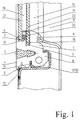
- the window 16 to be fastened consists of two interconnected window panes, while in FIGS. 3 to 6 the window 16 is formed from a simple window pane 24.
- the holder of the window 16 is formed by a circumferential elastic window profile 1, which has a known sealing lip 8 between the inner pane 19 and the window key 11 on the inside and a known wedge-shaped filler 7 on the outside 4 and in a known manner on the one hand by a vertical Holding web 14 is held in the window cutout 10 and on the other hand includes the window 16 in a U-shaped holding groove 2.
- the window profile 1 In order to meet today's guidelines for the design of modern commuter rail vehicles, the window profile 1 according to the invention has a flat outer surface 4 which is approximately flush with the outer paneling 15 of the vehicle, the edge parts of which are merely as covering lips 5; 6 to the outer disc 21 and the outer sheet 15 and are not considered with any holding functions.
- the window-side cover lip 6 is, as can be seen in FIGS. 1 to 3, at the same time provided as the outer side lip of the U-shaped retaining groove 2 and is relatively thin in order to arrange the window 16 in the retaining groove 2 flush with the outer paneling 15 of the vehicle to be able to.
- this retaining groove 2 there is also a further circumferential clamping groove 3 facing the retaining web 14 in the window cutout 10, in which the window 16 formed on its circumferential pane edge 17 with a web-like collar 18 is locked in the window cutout 10 and through which operating conditions that occur at the same time Pressure forces on the window 16 are recorded in the window profile 1.
- the web-like collar 18 on the pane edge 17 of the window 16 is, as can be seen from FIG. 1, preferably designed as an elongated edge portion 20 of the inner pane 19 in that the inner pane 19 is larger than the outer pane 21 and such connected to this, preferably glued, is that the circumferential pane edge 17 of the window 16 has a gradation.
- This gradation can be achieved by a design of the same shape and a central connection of the inner pane 19 and the outer pane 21 in an advantageous manner with the same height all round, or by a design of the same shape and / or an eccentric connection of the inner and outer pane 19; 21, with a corresponding depth of the clamping groove 3, also with different heights, for example higher at the upper and lower edge of the window 16 than at the side edges.
- the window holder according to the invention, it has proven advantageous to additionally at least partially encase the pane edge 17 of the window 16 by an end profile, which is not shown in the drawing, in order to increase the strength of the connection between the inner pane 19 and the outer pane 21 or the to minimize shear forces occurring in the event of a load on the extended edge portion 20 of the inner pane 19 which is operatively connected to the clamping groove 3 of the window profile 1.
- This end profile can be formed as part of the circumferential spacer profile 22 between the inner and outer pane 19; 21, which encloses the entire pane edge 17 of the window 16, part of it or only the extended edge portion 20 of the inner pane 19 or can also be formed as a separate edge profile , which is glued to the edge 17 of the pane in the same way.
- the window holder according to the invention when using a window 16 with a double pane, it is also possible for the web-like collar 18 on the pane edge 17 of the window 16, as shown in FIG. 2, to extend beyond the pane edge 17 of the circumferential spacer profile 22 between interior and outer pane 19; 21 form, which is in operative connection with the clamping groove 3 of the window profile 1.
- the pane edge 17 of the window 16 is formed in a known manner without gradation by the use of inner and outer panes 19; 21 of the same size, and the spacer profile 22 preferably has two further extension bars that protrude perpendicularly from the pane edge 17 of the window 16 , unspecified legs with which it surrounds the pane edge 17 of the window 16 and is additionally glued to it.
- the leg connected by these two legs to the inner pane 19 is also formed with the collar 18 pointing away from the pane edge 17 of the window 16 and in operative connection with the clamping groove 3 of the window profile 1, which preferably directly in Extension of the inner disc 19 is arranged on this leg.
- the window holder according to the invention when using a window 16 with a double pane, however, it is also possible for the web-like collar 18 on the pane edge 17 of the window 16, as shown in FIG. 3, as the web of an additional circumferential profile element pointing away from this pane edge 17 23 with a T-shaped profile cross-section, which is connected on the one hand via its leg to the pane edge 17 of the window 16 and on the other hand is operatively connected through its web to the clamping groove 3 of the window profile 1.
- the pane edge 17 of the window 16 and the spacer profile 23 between the inner pane 20 and the outer pane 22 are likewise formed in a known manner without gradation and without additional legs or the like.
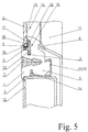
- the web-like collar 18 formed by the web of the profile element 23 is also preferably arranged in this embodiment in an extension of the inner pane 19, but can also be arranged here relative to the spacer profile 22 or at a location between the preferred variants mentioned. From Fig. 3 to 6 it can also be seen that the web-like collar 18 on the pane edge 17 of the window 16 when using a window 16 with a simple window pane 24 is formed as a circumferential extension of the pane edge 17 arranged offset towards the inside of the pane 25, with its Offset the level of the window 16 with the outer panel 15 of the vehicle can be determined.
- a web plate 27 of the type shown in FIG. 4, which is connected to the inside 25 of the pane, has proven to be a preferred embodiment of the extension of the pane edge 17, which is preferably glued to the window pane 24 on the one hand and is operatively connected to the clamping groove 3 of the window profile 1 on the other.
- FIG. 5 An alternative embodiment of the extension of the pane edge 17 when using a window 16 with a simple window pane 24, which is somewhat more expensive, but is characterized by a higher strength, is shown in FIG. 5.
- the extension of the edge of the pane 17 is formed as a T-shaped profile 28 which is preferably glued to a leg half 29 and to the web 31 both on the inside 25 of the pane and on the face 26 of the pane, the other half 30 of which is formed with the clamping groove 3 of the Window profile 1 is in operative connection.
- extension of the pane edge 17 in this embodiment is designed as an offset 32 of the window pane 24 itself, the part 33 parallel to the window pane 24 is in operative connection with the clamping groove 3 of the window profile 1.
- An additional advantage over the other embodiments in this variant is that separate profiles for the extension of the pane edge 17 are saved and the adhesive connections required thereby are avoided.
- the window profile 1 also preferably has an additional securing lip 9 below the sealing lip 8 between the inner pane 19 and the window key 11, which protrudes against the delimiting elements of the window cutout 10 indicated in FIGS. 1 to 6, such as side wall columns 12 and transverse frames 13 of the side wall frame.
- This locking lip 9 is designed to prevent rotation of the window profile 1 at extreme compressive forces on the window 16 and thereby causes the window profile 1 can no longer detach itself from its holder on the holding web 14 in the window cutout 10 when the compressive force is exerted on the inside Security and vandalism resistance.
- the circular cavity shown in Figs. 1 to 3 without reference numerals within the window profile 1 only has the function of reducing the weight of the window profile 1 slightly and improving its elasticity and manageability when installing the window.
Landscapes
- Engineering & Computer Science (AREA)
- Mechanical Engineering (AREA)
- Window Of Vehicle (AREA)
- Securing Of Glass Panes Or The Like (AREA)
- Platform Screen Doors And Railroad Systems (AREA)
Abstract
Description
Die Erfindung betrifft eine schwimmende Halterung von Fenstern in den Fensterausschnitten von Fahrzeugen, wobei das Fenster aus einer einfachen Fensterscheibe oder mindestens aus einer Doppelscheibe besteht und die Halterung durch ein im Fensterausschnitt umlaufendes, elastisches Fensterprofil gebildet wird, und sie läßt sich insbesondere vorteilhaft an Nahverkehrs-Schienenfahrzeugen realisieren.The invention relates to a floating mounting of windows in the window cutouts of vehicles, the window made up of a simple window pane or at least there is a double pane and the holder is held in place by a elastic window profile is formed, and it can be particularly advantageous on local rail vehicles realize.
Im Schienenfahrzeugbau ist es allgemein bekannt, daß beim Einbau von nicht beweglichen
Fenstern in die Fensterausschnitte des Wagenkastens grundsätzlich zwischen einer festen Fensterhalterung
und einer sogenannten schwimmenden Fensterhalterung unterschieden wird. Der
Unterschied zwischen diesen beiden Befestigungsarten besteht dabei darin, daß bei der festen
Fensterhalterung das mit einem Rahmen versehene Fenster im Fensterausschnitt am Seitenwandgerippe
des Fahrzeuges zumeist verschraubt oder verklebt wird, währenddessen bei der
schwimmenden Fensterhalterung das Fenster ohne Rahmen ausgebildet ist und lediglich durch
speziell geformte Fensterprofile im Fensterausschnitt gehalten wird. Während sich die feste
Fensterhalterung somit aufgrund der Möglichkeit, den bei Tunnelfahrten oder bei Zugbegegnungen
auftretenden hohen Lastwechseln an den Fenstern sicher standzuhalten, besonders für
Hochgeschwindigkeitszüge od. dgl. eignet, hat sich die schwimmende Fensterhalterung aufgrund
ihrer Vorzüge beim Ein- und Ausbau der Fenster sowie ihrer Stabilität gegen Zug-,
Druck- und Pufferstoßkräfte für Reisezugwagen und Nahverkehrs-Schienenfahrzeuge am vorteilhaftesten
erwiesen. Aus der Vielzahl bekannter Lösungen zu schwimmenden Fensterhalterungen
sind dabei solche Lösungen am gebräuchlichsten, bei denen das elastische Fensterprofil,
ähnlich wie bei den in der DD-PS 101 622 und in dem DE-GM 8 116 661 offenbarten Lösungen,
einerseits durch einen senkrechten Haltesteg oder eine schräge Druckkante sowie durch
eine die Außenbeblechung einseitig umgreifende Lippe im Fensterausschnitt gehalten wird und
andererseits das Fenster in einer U-förmigen Haltenut umfaßt. Darüber hinaus sind an der Innenseite
und/oder an der Außenseite des Fensterprofils keilförmige oder runde Füller vorgesehen,
die den erforderlichen Anpreßdruck des Fensterprofils auf die Halterungen im Fensterausschnitt
und auf das Fenster erzeugen.
Bei einer weiteren, durch das DE-GM 7 005 883 bekannten Lösung weist das ebenfalls einerseits
durch einen senkrechten Haltesteg im Fensterausschnitt gehaltene und andererseits das
Fenster in einer U-förmigen Haltenut umfassende, elastische Fensterprofil darüber hinaus an
der Innenseite eine Dichtlippe zwischen Innenscheibe und Fensterschlüssel auf gegen deren
Hals sich der Fensterschlüssel im Bereich des gefaßten Scheibenrandes abstützt. Der auch hier
zur Anwendung kommende keilförmige Füller wird dabei von der Außenseite des Fensterprofils
her im Bereich zwischen dem Rand des Fensters und dem Haltesteg eingesetzt. In rail vehicle construction, it is generally known that when non-moving windows are installed in the window cutouts of the car body, a fundamental distinction is made between a fixed window holder and a so-called floating window holder. The difference between these two types of fastening is that in the fixed window bracket the window with a frame in the window cutout is mostly screwed or glued to the side wall frame of the vehicle, while in the floating window bracket the window is designed without a frame and only by specially shaped window profiles is held in the window. While the fixed window holder is particularly suitable for high-speed trains or the like due to the possibility of safely withstanding the high load changes on the windows that occur during tunnel journeys or train encounters, the floating window holder has, because of its advantages, the installation and removal of the windows as well its stability against train, pressure and buffer impact forces for passenger cars and local rail vehicles proved most advantageous. Out of the multitude of known solutions for floating window mounts, the most common are those in which the elastic window profile, similar to the solutions disclosed in DD-PS 101 622 and in DE-GM 8 116 661, on the one hand by a vertical retaining web or an oblique pressure edge and is held by a lip encompassing the outer sheet on one side in the window cutout and on the other hand encloses the window in a U-shaped holding groove. In addition, on the inside and / or on the outside of the window profile, wedge-shaped or round fillers are provided, which generate the required contact pressure of the window profile on the holders in the window cutout and on the window.
In another solution known from DE-GM 7 005 883, the elastic window profile, which is likewise held on the one hand by a vertical retaining web in the window cutout and on the other hand comprises the window in a U-shaped holding groove, on the inside also has a sealing lip between the inner pane and the window key against whose neck the window key is supported in the area of the framed pane edge. The wedge-shaped filler used here is used from the outside of the window profile in the area between the edge of the window and the retaining web.
Der Nachteil solcher bekannten schwimmenden Fensterhalterungen ist jedoch, daß die Kraftaufnahme
gegen betriebsbedingte Zug- und Druckkräfte auf das Fenster immer unmittelbar
innerhalb der U-förmigen Haltenut im Fensterprofil vorgesehen ist, so daß die seitlichen Lippen
der U-förmigen Haltenut relativ stark beziehungsweise voluminös dimensioniert werden müssen.
Dies hat wiederum zur Folge, daß zwar das Fensterprofil noch annähernd bündig zur Außenbeblechung
des Fahrzeuges im Fensterausschnitt befestigt werden kann, das Fenster selbst
jedoch immer nur entgegen den heutigen Gestaltungsrichtlinien von modernen Nahverkehrs-Schienenfahrzeugen
zur Außenbeblechung etwas zurückgesetzt im Fensterausschnitt gehalten
wird. Das GB-A-2 083 106 weist ein Fenster mit einer
schwimenden Fensterhalterung, mit den Merkmalen des
Oberbegriffes des Anspruchs 1.
Die Erfindung verfolgt somit das Ziel, eine schwimmende Fensterhalterung an Reisezugwagen
derart auszubilden, daß die genannten Mängel des Standes der Technik beseitigt werden.The disadvantage of such known floating window mounts is, however, that the force absorption against operational tensile and compressive forces on the window is always provided directly within the U-shaped holding groove in the window profile, so that the lateral lips of the U-shaped holding groove are dimensioned relatively strong or voluminous have to. This in turn has the consequence that the window profile can still be fastened in the window cutout approximately flush with the outside paneling of the vehicle, but the window itself is always held in a slightly recessed manner in the window cutout, contrary to today's design guidelines of modern commuter rail vehicles for the outside paneling. GB-A-2 083 106 has a window with a floating window holder, with the features of the preamble of
The invention thus pursues the aim of designing a floating window holder on passenger carriages in such a way that the deficiencies of the prior art are eliminated.
Als Aufgabe liegt der Erfindung die Konzipierung einer schwimmende Fensterhalterung an
Reisezugwagen, insbesondere an Nahverkehrs-Schienenfahrzeugen, zugrunde, mit welcher sowohl
das elastische Fensterprofil als auch das Fenster selbst bündig zur Außenbeblechung des
Fahrzeuges im Fensterausschnitt arretierbar sind.
Die Aufgabe wird mit einer gattungsgemäßen schwimmenden Fensterhalterung nach dem
Oberbegriff des Anspruchs 1 durch die Merkmale des Kennzeichens des Anspruchs 1 gelöst.
Zweckmäßige Ausgestaltungen des Gegenstandes der Erfindung sind in den Unteransprüchen
2 bis 9 angegeben.
Der Vorteil der erfindungsgemäßen schwimmenden Fensterhalterung gegenüber dem Stand der
Technik ist, daß durch die zusätzliche Klemmnut innerhalb der U-förmigen Haltenut des Fensterprofils
die Kraftaufnahme gegen betriebsbedingte Druckkräfte auf das Fenster innerhalb des
Fensterprofils und nicht durch die Seitenlippen der U-förmigen Haltenut erfolgen kann. Dadurch
ist es möglich, das Fenster, entsprechend heutiger Gestaltungsrichtlinien für moderne
Nahverkehrs-Schienenfahrzeuge, bündig zur Außenbeblechung im Fensterprofil zu arretieren
und die Außenseite des Fensterprofils, da diese keinerlei Haltefunktionen mehr hat, entsprechend
eben und mit dünnen Randlippen auszubilden sowie ebenfalls annähernd bündig zur Außenbeblechung
des Fahrzeuges im Fensterausschnitt anzuordnen.
Ein Ausführungsbeispiel der Ertindung ist in den dazugehörigen Zeichnungen schematisch dargestellt
und wird nachfolgend ausführlich erläutert.Die Zeichnungen zeigen dabei in
- Fig. 1 -
- die erfindungsgemäße Fensterhalterung für eine Doppelscheibe im Schnitt
- Fig. 2 -
- eine Variante der erfindungsgemäßen Fensterhalterung für eine Doppelscheibe im Schnitt
- Fig. 3 -
- eine weitere Variante der erfindungsgemäßen Fensterhalterung für eine Doppelscheibe im Schnitt
- Fig. 4 -
- die erfindungsgemäße Fensterhalterung für eine einfache Fensterscheibe im Schnitt
- Fig. 5 -
- eine Variante der erfindungsgemäßen Fensterhalterung für eine einfache Fensterscheibe im Schnitt
- Fig. 6 -
- eine weitere Variante der erfindungsgemäßen Fensterhalterung für eine einfache Fensterscheibe im Schnitt
The object is achieved with a generic floating window holder according to the preamble of
The advantage of the floating window holder according to the invention over the prior art is that the additional clamping groove inside the U-shaped holding groove of the window profile means that the force can be absorbed against operational pressure forces on the window inside the window profile and not through the side lips of the U-shaped holding groove. This makes it possible to lock the window flush with the outside paneling in the window profile, in accordance with today's design guidelines for modern commuter rail vehicles, and to design the outside of the window profile as level and with thin edge lips, since it no longer has any holding functions, and also approximately flush with the outside paneling to arrange the vehicle in the window.
An embodiment of the invention is shown schematically in the accompanying drawings and is explained in detail below
- Fig. 1 -
- the window holder according to the invention for a double pane on average
- Fig. 2 -
- a variant of the window holder according to the invention for a double pane in section
- Fig. 3 -
- a further variant of the window holder according to the invention for a double pane in section
- Fig. 4 -
- the window holder according to the invention for a simple window pane on average
- Fig. 5 -
- a variant of the window bracket according to the invention for a simple window pane in section
- Fig. 6 -
- a further variant of the window holder according to the invention for a simple window pane in section
In den Fig. 1 bis 3 ist deutlich zu sehen, daß das zu befestigende Fenster 16 aus zwei miteinander
verbundenen Fensterscheiben besteht, während in den Fig. 3 bis 6 das Fenster 16 aus
einer einfachen Fensterscheibe 24 gebildet wird. Die Halterung des Fensters 16 wird dabei
durch ein umlaufendes elastisches Fensterprofil 1 gebildet, welches an der Innenseite eine bekannte
Dichtlippe 8 zwischen Innenscheibe 19 und Fensterschlüssel 11 sowie an der Außenseite
4 einen bekannten keilförmigen Füller 7 aufweist und in an sich bekannter Weise einerseits
durch einen senkrechten Haltesteg 14 im Fensterausschnitt 10 gehalten wird sowie andererseits
das Fenster 16 in einer U-förmigen Haltenut 2 umfaßt.
Um nunmehr den heutigen Richtlinien bei der Gestaltung moderner Nahverkehrs-Schienenfahrzeuge
gerecht zu werden, weist das Fensterprofil 1 erfindungsgemäß eine ebene, zur Außenbeblechung
15 des Fahrzeuges annähernd bündige Außenseite 4 auf, deren Randpartien lediglich
als Abdecklippen 5; 6 zur Außenscheibe 21 und zur Außenbeblechung 15 ausgebildet und
mit keinerlei Haltefunktionen bedacht sind. Die fensterseitige Abdecklippe 6 ist dabei, wie in
den Fig. 1 bis 3 zu sehen ist, zugleich als äußere Seitenlippe der U-förmigen Haltenut 2 vorgesehen
und relativ dünn ausgebildet, um das Fenster 16 in der Haltenut 2 bündig zur Außenbeblechung
15 des Fahrzeuges anordnen zu können. Innerhalb dieser Haltenut 2 ist darüber hinaus
eine weitere, zum Haltesteg 14 im Fensterausschnitt 10 weisende, umlaufende Klemmnut 3
angeordnet, in welcher das an seinem umlaufenden Scheibenrand 17 mit einem stegartigen Kragen
18 ausgebildete Fenster 16 im Fensterausschnitt 10 arretiert wird und durch welche zugleich
auftretende betriebsbedingte Druckkräfte auf das Fenster 16 im Fensterprofil 1 aufgenommen
werden. Bei Verwendung eines Fensters 16 mit Doppelscheibe ist der stegartige Kragen
18 am Scheibenrand 17 des Fensters 16 dabei, wie aus Fig. 1 ersichtlich ist, bevorzugt als
verlängerte Randpartie 20 der Innenscheibe 19 ausgebildet, indem die Innenscheibe 19 größer
als die Außenscheibe 21 ausgebildet und derart mit dieser verbunden, vorzugsweise verklebt,
ist, daß der umlaufende Scheibenrand 17 des Fensters 16 eine Abstufung aufweist. Diese Abstufung
kann durch eine formgleiche Ausbildung sowie zentrische Verbindung von Innenscheibe
19 und Außenscheibe 21 in vorteilhafter Weise mit umlaufend gleicher Höhe oder durch
formungleiche Ausbildung und/oder exzentrische Verbindung von Innen- und Außenscheibe
19; 21, bei entsprechender Tiefe der Klemmnut 3, auch mit unterschiedlicher Höhe, beispielsweise
am oberen und unteren Rand des Fensters 16 höher als an den Seitenrändern, ausgebildet
werden.
Darüber hinaus hat es sich bei dieser Ausführungsform der erfindungsgemäßen Fensterhalterung
als vorteilhaft erwiesen, den Scheibenrand 17 des Fensters 16 zusätzlich durch ein in der
Zeichnung nicht dargestelltes Abschlußprofil zumindest teilweise zu ummanteln, um die Festigkeit
der Verbindung zwischen Innenscheibe 19 und Außenscheibe 21 zu erhöhen beziehungsweise
die im Lastfall auftretenden Scherkräfte auf die mit der Klemmnut 3 des Fensterprofils
1 in Wirkverbindung stehende, verlängerte Randpartie 20 der Innenscheibe 19 zu minimieren.
Dieses Abschlußprofil kann dabei als Teil des umlaufenden Abstandhalterprofils 22
zwischen Innen- und Außenscheibe 19;21 ausgebildet sein, welches den gesammten Scheibenrand
17 des Fensters 16, einen Teil davon oder nur die verlängerte Randpartie 20 der Innenscheibe
19 umschließt oder auch als gesondertes Randprofil ausgebildet werden, welches in
gleicher Weise den Scheibenrand 17 umschließend an diesem verklebt ist.
Als alternative Ausführungsform der erfindungsgemäßen Fensterhalterung bei Verwendung
eines Fensters 16 mit Doppelscheibe ist es auch möglich, den stegartigen Kragen 18 am Scheibenrand
17 des Fensters 16, wie in Fig. 2 abgebildet, als über diesen Scheibenrand 17 hinausragende
Verlängerung des umlaufenden Abstandhalterprofils 22 zwischen Innen- und Außenscheibe
19; 21 auszubilden, welche mit der Klemmnut 3 des Fensterprofils 1 in Wirkverbindung
steht. Der Scheibenrand 17 des Fensters 16 ist dabei durch die Verwendung von gleichgroßen
Innen- und Außenscheiben 19;21 in bekannter Weise ohne Abstufung ausgebildet und
das Abstandhalterprofil 22 weist dabei bevorzugt zwei weitere, von einem senkrecht aus dem
Scheibenrand 17 des Fensters 16 herausragenden Verlängerungssteg aus rechtwinklige, nicht
näher bezeichnete Schenkel auf, mit denen es den Scheibenrand 17 des Fensters 16 umschließt
und an diesem zusätzlich verklebt ist. Wie aus Fig. 2 ersichtlich ist, ist der von diesen beiden
Schenkeln mit der Innenscheibe 19 verbundene Schenkel darüber hinaus mit dem vom Scheibenrand
17 des Fensters 16 wegweisenden und mit der Klemmnut 3 des Fensterprofils 1 in
Wirkverbindung stehenden Kragen 18 ausgebildet, welcher bevorzugt direkt in Verlängerung
der Innenscheibe 19 an diesem Schenkel angeordnet ist. Bei Bedarf ist jedoch auch dessen Anordnung
direkt gegenüber dem Verlängerungssteg des Abstandhalterprofils 22 möglich oder an
einer Stelle zwischen den genannten Vorzugsvarianten.
In weiterer alternativer Ausführung der erfindungsgemäßen Fensterhalterung bei Verwendung
eines Fensters 16 mit Doppelscheibe ist es jedoch auch möglich, den stegartigen Kragen 18 am
Scheibenrand 17 des Fensters 16, wie in Fig. 3 abgebildet, als den von diesem Scheibenrand 17
wegweisenden Steg eines zusätzlichen umlaufenden Profilelementes 23 mit T-förmigen Profilquerschnitt
auszubilden, welches einerseits über seinem Schenkel mit dem Scheibenrand 17 des
Fensters 16 verbunden ist und andererseits durch seinen Steg mit der Klemmnut 3 des Fensterprofils
1 in Wirkverbindung steht. Der Scheibenrand 17 des Fensters 16 und das Abstandhalterprofil
23 zwischen der Innenscheibe 20 und der Außenscheibe 22 sind hierbei ebenfalls in
bekannter Weise ohne Abstufung sowie ohne zusätzliche Schenkel od. dgl. ausgebildet. Hinsichtlich
einer besseren Festigkeit der Verbindung zwischen dem Scheibenrand 17 des Fensters
16 und dem T-förmigen Profilelement 23 ist es dabei von Vorteil, den Schenkel des Profilelementes
23, wie in der in Fig. 3 gezeigten Ausführungsform, zusätzlich derart rechtwinklig abzuwinkeln,
daß dieser sowohl den Scheibenrand 17 des Fensters 16 als auch geringfügig die
innere Randpartie der Innenscheibe 19 umschließt und an diesen verklebt werden kann. Der
von dem Steg des Profilelementes 23 gebildete stegartige Kragen 18 ist auch bei dieser Ausführungsform
bevorzugt in Verlängerung der Innenscheibe 19 angeordnet, kann aber auch hier
gegenüber dem Abstandhalterprofil 22 oder an einer Stelle zwischen den genannten Vorzugsvarianten
angeordnet werden.
Aus den Fig. 3 bis 6 ist darüber hinaus erkennbar, daß der stegartige Kragen 18 am Scheibenrand
17 des Fensters 16 bei Verwendung eines Fensters 16 mit einfacher Fensterscheibe 24 als
nach der Scheibeninnenseite 25 hin versetzt angeordnete umlaufende Verlängerung des Scheibenrandes
17 ausgebildet ist, mit deren Versatz die Bündigkeit des Fensters 16 mit der Außenbeblechung
15 des Fahrzeuges bestimmbar ist. Ebenso wie bei doppelscheibigen Fenstern ist es
somit auch bei der Verwendung einscheibiger Fenster möglich, die für die Bündigkeit des Fensters
16 mit der Außenbeblechung 15 entscheidenden Einflußfaktoren durch Variierung des
Versatzmaßes der Verlängerung des Scheibenrandes 17, verbunden mit entsprechenden Lageänderungen
der Klemmnut 3 im Fensterprofil 1, zu beeinflussen.
Als bevorzugte Realisierungsform der Verlängerung des Scheibenrandes 17 hat sich ein mit der
Scheibeninnenseite 25 verbundenes Stegblech 27 der in Fig. 4 abgebildeten Art erwiesen, welches
einerseits mit der Fensterscheibe 24 bevorzugt verklebt ist und andererseits mit der
Klemmnut 3 des Fensterprofils 1 in Wirkverbindung steht. Das in Fig. 4 gezeigte, im Profilquerschnitt
gerade Stegblech 27 kann jedoch auch mit einem Z-förmigen oder mit einem anderen
ähnlichen Profilquerschnitt ausgebildet werden, wenn sich dies als erforderlich erweist,
beziehungsweise auch aus einem nichtmetallischen Werkstoff bestehen.
Eine alternative Ausführungsform der Verlängerung des Scheibenrandes 17 bei Verwendung
eines Fensters 16 mit einfacher Fensterscheibe 24, die zwar etwas kostenaufwendiger ist, sich
jedoch durch eine höhere Festigkeit auszeichnet, ist in Fig. 5 dargestellt. Bei dieser Ausführung
ist die Verlängerung des Scheibenrandes 17 als ein mit einer Schenkelhälfte 29 und mit dem
Steg 31 sowohl an der Scheibeninnenseite 25 als auch an der Scheibenstirnseite 26 bevorzugt
verklebtes T-förmiges Profil 28 ausgebildet, dessen andere Schenkel hälfte 30 mit der Klemmnut
3 des Fensterprofils 1 in Wirkverbindung steht. Durch die Verbindung der einen Schenkelhälfte
29 und des Steges 31 des Profils 28 mit der Fensterscheibe 24 ist bei dieser Ausführung
eine erhöhte Festigkeit der Verbindung zwischen dem Profil 28 und der Fensterscheibe 24 erreichbar,
wobei auch hier metallische oder nichtmetallische Profile zum Einsatz kommen können.
Als Modifikation zu dem in Fig. 5 abgebildeten T-förmigen Profil 28 ist es auch möglich,
die mit der Klemmnut 3 des Fensterprofils 1 in Wirkverbindung stehende in gerader Verlängerung
zu der mit dem Fenster 16 verklebten Schenkelhälfte 29 angeordnete Schenkelhälfte 30
des Profils 28, beispielsweise durch eine Kröpfung in Steghöhe, in Richtung Fahrzeuginneres
zu der einen Schenkelhälfte 29 versetzt auszubilden, so daß der gesamte Schenkel des Profils
28 Z-förmig ausgebildet ist und die Stabilität der Fensterhalterung weiter erhöht wird.
Mit der in Fig. 6 abgebildeten Fensterhalterung wird darüber hinaus noch eine weitere Variante
zur Ausbildung der Verlängerung des Scheibenrandes 17 dargestellt, mit der die gleichen Vorteile
wie mit den vorgenannten Ausführungsformen erzielbar sind. Dabei ist deutlich erkennbar,
daß die Verlängerung des Scheibenrandes 17 bei dieser Ausführungsform als randseitige Kröpfung
32 der Fensterscheibe 24 selbst ausgebildet ist, deren zur Fensterscheibe 24 paralleler Teil
33 mit der Klemmnut 3 des Fensterprofils 1 in Wirkverbindung steht. Ein zusätzlicher Vorteil
gegenüber den anderen Ausführungsformen ist bei dieser Variante, daß gesonderte Profile für
die Verlängerung des Scheibenrandes 17 eingespart und die damit notwendigen Klebeverbindungen
vermieden werden.
Als Ausgestaltung der erfindungsgemäßen Fensterhalterung weist das Fensterprofil 1 darüber
hinaus bevorzugt unterhalb der Dichtlippe 8 zwischen Innenscheibe 19 und Fensterschlüssel 11
noch eine zusätzliche Sicherungslippe 9 auf, welche sich gegen die in Fig. 1 bis 6 angedeuteten
Begrenzungselemente des Fensterausschnittes 10, wie Seitenwandsäulen 12 und Querspanten
13 des Seitenwandgerippes, abstützt. Diese Sicherungslippe 9 ist als Verdrehsicherung des
Fensterprofils 1 bei extremen Druckkräften auf das Fenster 16 ausgebildet und bewirkt dadurch,
daß das Fensterprofil 1 sich bei Druckkraft auf die Innenseite des Fensters 16 nicht
mehr von seiner Halterung auf dem Haltesteg 14 im Fensterausschnitt 10 lösen kann eine optimale
Sicherheit und Vandalismusresisdenz.
Erwähnt werden soll noch, daß der in den Fig. 1 bis 3 ohne Bezugszeichen dargestellte kreisförmige
Hohlraum innerhalb des Fensterprofils 1 lediglich die Funktion hat, das Gewicht des
Fensterprofils 1 geringfügig zu mindern und dessen Elastizität und Handhabbarkeit beim Fenstereinbau
zu verbessern.1 to 3 it can clearly be seen that the
In order to meet today's guidelines for the design of modern commuter rail vehicles, the
In addition, in this embodiment of the window holder according to the invention, it has proven advantageous to additionally at least partially encase the
As an alternative embodiment of the window holder according to the invention when using a
In a further alternative embodiment of the window holder according to the invention when using a
From Fig. 3 to 6 it can also be seen that the web-
A
An alternative embodiment of the extension of the
The window holder shown in FIG. 6 also shows a further variant for the formation of the extension of the
As an embodiment of the window holder according to the invention, the
It should also be mentioned that the circular cavity shown in Figs. 1 to 3 without reference numerals within the
Claims (9)
- Window having a floating window mounting for single-pane or multiple-pane glazing for vehicles, in particular suburban rail vehicles, the window mounting being formed by a peripheral, elastic window profile (1) which, on the one hand, is retained in the window cutout (10) by a perpendicular retaining web (14) and, on the other hand, grasps the window (16) in a U-shaped retaining groove (2) and also has a flat outside (4), which is approximately flush with the exterior cladding (15) of the vehicle and whose edge portions are designed as covering lips (5; 6), the covering lip (6) on the window side being provided at the same time as an exterior side lip of the U-shaped retaining groove (2), characterized in that on the inside, the window profile (1) has a sealing lip (8) between the inside (25) of the window pane and the window key (11) and also, on the outside, has a wedge-shaped filler (7) which is arranged in the region between the window-pane edge (17) of the window (16) and the retaining web (14), and in that within the retaining groove (2) there is arranged a further, peripheral clamping groove (3) which points towards the retaining web (14) in the window cutout (10) and in which the window (16), which is formed with a web-like collar (18) on its peripheral window-pane edge (17), can be locked in place in the window cutout (10) in a manner such that it is likewise flush with the exterior cladding (15) of the vehicle, and by means of which, at the same time, operationally caused compressive forces acting on the window (16) can be absorbed in the window profile (1).
- Floating window mounting according to Claim 1, characterized in that when a window (16) is used with a double window pane, the web-like collar (18) on the window-pane edge (17) of the window (16) is preferably designed as an extended edge portion (20) of the inner window pane (19) by the inner window pane (19) being designed such that it is larger than the outer window pane (21), the extended edge portion (20) of the inner window pane (19) being operatively connected to the clamping groove (3) of the window profile (1).
- Floating window mounting according to Claim 1, characterized in that when a window (16) is used with a double window pane, the web-like collar (18) on the window-pane edge (17) of the window (16) is designed as an extension, which protrudes over this window-pane edge (17), of the peripheral spacer profile (22) between the inner window pane and outer window pane (19; 21), which extension is operatively connected to the clamping groove (3) of the window profile (1).
- Floating window mounting according to Claim 1, characterized in that when a window (16) is used with a double window pane, the web-like collar (18) on the window-pane edge (17) of the window (16) is designed as the web, which points away from this window-pane edge (17), of an additional, peripheral profile element (23) having a T-shaped profile cross section, which profile element, on the one hand, is connected via its leg to the window-pane edge (17) of the window (16) and, on the other hand, is operatively connected by its web to the clamping groove (3) of the window profile (1).
- Floating window mounting according to Claim 1, characterized in that when a window (16) is used with a single window pane (24), the web-like collar (18) on the window-pane edge (17) of the window (16) is designed as a peripheral extension of the window-pane edge (17), which extension is arranged offset towards the inside (25) of the window pane and whose offset can be used to determine the flush-mounting of the window (16) with the exterior cladding (15) of the vehicle.
- Floating window mounting according to Claim 1 and 5, characterized in that when a window (16) having a single window pane (24) is used, the extension of the window-pane edge (17) is designed as a web plate (27) which is connected to the inside (25) of the window pane, is, on the one hand, preferably bonded to the window pane (24) and, on the other hand, is operatively connected to the clamping groove (3) of the window profile (1).
- Floating window mounting according to Claim 1 and 5, characterized in that when a window (16) having a single window pane (24) is used, the extension of the window-pane edge (17) is designed as a T-shaped profile (28) which is preferably bonded, both on the inside (25) of the window pane and also on the end side (26) of the window pane, to a leg half (29) and to the web (31) and whose other leg half (30) is operatively connected to the clamping groove (3) of the window profile (1).
- Floating window mounting according to Claim 1 and 5, characterized in that when a window (16) having a single window pane (24) is used, the extension of the window-pane edge (17) is preferably designed as a right-angled bend (32) on the edge side of the window pane (24) itself, whose part (33) which is parallel to the window pane (24) is operatively connected to the clamping groove (3) of the window profile (1).
- Floating window mounting according to Claims 1 to 8, characterized in that the window profile (1), preferably below the sealing lip (8) to the window key (11), has an additional securing lip (9) which is designed as a means of protecting the window profile (1) against becoming distorted in the event of extreme compressive forces on the window (16), and is operatively connected to the boundary elements of the window cutout (10), for example side wall pillars (12) and transverse ribs (13) of the side-wall frame.
Applications Claiming Priority (4)
| Application Number | Priority Date | Filing Date | Title |
|---|---|---|---|
| DE4438266A DE4438266C2 (en) | 1994-10-26 | 1994-10-26 | Floating window holder on passenger coaches, especially on local rail vehicles |
| DE4438266 | 1994-10-26 | ||
| DE19519415A DE19519415A1 (en) | 1994-10-26 | 1995-05-26 | Floating holder for vehicle window |
| DE19519415 | 1995-05-26 |
Publications (2)
| Publication Number | Publication Date |
|---|---|
| EP0709269A1 EP0709269A1 (en) | 1996-05-01 |
| EP0709269B1 true EP0709269B1 (en) | 2000-01-19 |
Family
ID=25941402
Family Applications (1)
| Application Number | Title | Priority Date | Filing Date |
|---|---|---|---|
| EP95116446A Expired - Lifetime EP0709269B1 (en) | 1994-10-26 | 1995-10-19 | Floating support of a window for vehicles, especially for railway vehicles used for regional traffic |
Country Status (6)
| Country | Link |
|---|---|
| EP (1) | EP0709269B1 (en) |
| AT (1) | ATE188927T1 (en) |
| DE (1) | DE4438266C2 (en) |
| DK (1) | DK0709269T3 (en) |
| ES (1) | ES2142984T3 (en) |
| PT (1) | PT709269E (en) |
Cited By (1)
| Publication number | Priority date | Publication date | Assignee | Title |
|---|---|---|---|---|
| DE102013204992A1 (en) * | 2013-03-21 | 2014-09-25 | Bombardier Transportation Gmbh | Holder for a window unit |
Families Citing this family (9)
| Publication number | Priority date | Publication date | Assignee | Title |
|---|---|---|---|---|
| DE19711368A1 (en) | 1997-03-19 | 1998-09-24 | Man Nutzfahrzeuge Ag | Vehicle door with optional registered or double pane glazing |
| DE19829737A1 (en) * | 1998-07-03 | 2000-01-13 | Huebner Gummi & Kunststoff | Window frame profile for a vehicle |
| DE20015632U1 (en) | 2000-09-09 | 2000-12-14 | DaimlerChrysler AG, 70567 Stuttgart | Rail vehicle with windows |
| DE10051919A1 (en) * | 2000-10-19 | 2002-05-02 | Alstom Lhb Gmbh | Window installation system for vehicles |
| DE102004021762A1 (en) * | 2004-04-30 | 2005-11-17 | Cleff Fahrzeugteile Gmbh & Co Kg | Retaining fixture and seal for railway car or omnibus window has secondary inner seal in contact with glass edge |
| GB2510568B (en) * | 2013-02-06 | 2015-10-14 | Percy Lane Products Ltd | Transport window arrangement |
| EP3604009A1 (en) * | 2018-07-31 | 2020-02-05 | Hübner GmbH & Co. KG | Profile body for receiving and holding a window pane and window system |
| CN109178002A (en) * | 2018-08-29 | 2019-01-11 | 中车青岛四方机车车辆股份有限公司 | Forms mounting structure and rail vehicle with it |
| DE102019102125A1 (en) * | 2019-01-29 | 2020-07-30 | Volkswagen Aktiengesellschaft | Sealing element and method for sealing a vehicle body |
Family Cites Families (11)
| Publication number | Priority date | Publication date | Assignee | Title |
|---|---|---|---|---|
| US2356878A (en) * | 1940-11-05 | 1944-08-29 | Pittsburgh Plate Glass Co | Vehicular glazing construction |
| US2532130A (en) * | 1946-08-30 | 1950-11-28 | Pullman Standard Car Mfg Co | Window mounting |
| DE899152C (en) * | 1951-01-19 | 1953-12-07 | Sven Axel Eriksson Dipl Ing | Arrangement for fastening windows, in particular windshields, to motor vehicles |
| DE7005883U (en) * | 1970-02-19 | 1970-06-04 | Linke Hofmann Busch | ARRANGEMENT FOR SEALING WINDOW CUT-OUTS ON VEHICLES, IN PARTICULAR RAIL VEHICLES. |
| DD101622A1 (en) * | 1973-02-05 | 1973-11-12 | ||
| IT1143384B (en) * | 1981-02-12 | 1986-10-22 | Comind Spa Azienda Ages | IMPROVEMENT OF FIXED CRYSTAL VEHICLE CONNECTION SYSTEMS IN GENERAL PARTICULARLY CARS |
| DE8116661U1 (en) * | 1981-06-05 | 1981-10-15 | Linke-Hofmann-Busch, Waggon-Fahrzeug-Maschinen Gmbh, 3320 Salzgitter | WINDOW EDGE, IN PARTICULAR FOR TRAVELER CARS |
| JPS58189481A (en) * | 1982-04-21 | 1983-11-05 | ドラフテツクス・デイヴエロツプメント・アクチエンゲゼルシヤフト | Window |
| DE3301757C2 (en) * | 1983-01-20 | 1985-02-21 | Messerschmitt-Bölkow-Blohm GmbH, 8012 Ottobrunn | Vehicle window |
| DE3726924A1 (en) * | 1986-08-21 | 1988-03-03 | Volkswagen Ag | Mounting of a window pane in a vehicle |
| FR2679592A1 (en) * | 1991-07-12 | 1993-01-29 | Klein Ets Georges | GLAZING, PARTICULARLY FOR RAILWAY OR ROAD VEHICLE WINDOW. |
-
1994
- 1994-10-26 DE DE4438266A patent/DE4438266C2/en not_active Expired - Fee Related
-
1995
- 1995-10-19 AT AT95116446T patent/ATE188927T1/en active
- 1995-10-19 EP EP95116446A patent/EP0709269B1/en not_active Expired - Lifetime
- 1995-10-19 ES ES95116446T patent/ES2142984T3/en not_active Expired - Lifetime
- 1995-10-19 PT PT95116446T patent/PT709269E/en unknown
- 1995-10-19 DK DK95116446T patent/DK0709269T3/en active
Cited By (1)
| Publication number | Priority date | Publication date | Assignee | Title |
|---|---|---|---|---|
| DE102013204992A1 (en) * | 2013-03-21 | 2014-09-25 | Bombardier Transportation Gmbh | Holder for a window unit |
Also Published As
| Publication number | Publication date |
|---|---|
| DK0709269T3 (en) | 2000-05-29 |
| ATE188927T1 (en) | 2000-02-15 |
| PT709269E (en) | 2000-05-31 |
| DE4438266A1 (en) | 1996-05-09 |
| ES2142984T3 (en) | 2000-05-01 |
| DE4438266C2 (en) | 1999-02-25 |
| EP0709269A1 (en) | 1996-05-01 |
Similar Documents
| Publication | Publication Date | Title |
|---|---|---|
| EP1027223B1 (en) | Integral inside door reinforcement | |
| DE4106715C2 (en) | Side window for a motor vehicle | |
| EP0709269B1 (en) | Floating support of a window for vehicles, especially for railway vehicles used for regional traffic | |
| DE2228870A1 (en) | ARRANGEMENT FOR FASTENING A GLASS PANEL, IN PARTICULAR A WINDSHIELD OF A MOTOR VEHICLE | |
| DE102019213427A1 (en) | Window guide for a window pane of a motor vehicle | |
| DE19959602A1 (en) | Window frame for motor vehicle has cover filling gap between window edge and frame and provided with strip-form fastening protrusion with cross sectional thickened portion forming front and rear bevelled spreading surfaces | |
| EP0155554B1 (en) | Positioning device for motor vehicle windows | |
| DE19519415A1 (en) | Floating holder for vehicle window | |
| DE102017006481A1 (en) | Vehicle door and body | |
| EP4263252A1 (en) | Vehicle, vehicle door and window assembly therefor | |
| EP0113095B1 (en) | Vehicle door | |
| DE2712799A1 (en) | WINDOWS, IN PARTICULAR FOR VEHICLES | |
| DE60225233T2 (en) | Closing device of a vehicle opening with a rotatably movable disk and associated vehicle | |
| DE3118719A1 (en) | Windows for vehicles | |
| DE9417934U1 (en) | Windows for floating mounting on passenger coaches, especially on local rail vehicles | |
| EP1277910B1 (en) | Drop seal for door without threshold | |
| EP3024679B1 (en) | Sealing profile for connecting an attachment part to a window, and sealing arrangement | |
| DE3541325A1 (en) | Connecting element | |
| DE10134697B4 (en) | Vehicle door with carrier part and door panel attachable thereto | |
| WO1992012890A1 (en) | Passenger car with lateral door sills | |
| EP0736436B1 (en) | Railway vehicle | |
| DE10139593A1 (en) | Airbag device for a motor vehicle | |
| DE29924008U1 (en) | Motor vehicle tailgate with glued-on window and removable outer door wall | |
| DE10219957A1 (en) | Vehicle roof for fitting in bodywork has finishing panel to cover edge region of roof from above | |
| DE2154251C3 (en) | Upper mounting of the fixed side parts, such as frameless side windows or side walls, for the superstructures of tractors, mobile construction machines and similar vehicles |
Legal Events
| Date | Code | Title | Description |
|---|---|---|---|
| PUAI | Public reference made under article 153(3) epc to a published international application that has entered the european phase |
Free format text: ORIGINAL CODE: 0009012 |
|
| AK | Designated contracting states |
Kind code of ref document: A1 Designated state(s): AT BE CH DE DK ES FR GB IT LI NL PT SE |
|
| 17P | Request for examination filed |
Effective date: 19960517 |
|
| 17Q | First examination report despatched |
Effective date: 19980831 |
|
| RAP1 | Party data changed (applicant data changed or rights of an application transferred) |
Owner name: HUEBNER GUMMI- UND KUNSTSTOFF GMBH Owner name: DWA DEUTSCHE WAGGONBAU GMBH |
|
| GRAG | Despatch of communication of intention to grant |
Free format text: ORIGINAL CODE: EPIDOS AGRA |
|
| GRAG | Despatch of communication of intention to grant |
Free format text: ORIGINAL CODE: EPIDOS AGRA |
|
| GRAH | Despatch of communication of intention to grant a patent |
Free format text: ORIGINAL CODE: EPIDOS IGRA |
|
| GRAH | Despatch of communication of intention to grant a patent |
Free format text: ORIGINAL CODE: EPIDOS IGRA |
|
| GRAA | (expected) grant |
Free format text: ORIGINAL CODE: 0009210 |
|
| AK | Designated contracting states |
Kind code of ref document: B1 Designated state(s): AT BE CH DE DK ES FR GB IT LI NL PT SE |
|
| REF | Corresponds to: |
Ref document number: 188927 Country of ref document: AT Date of ref document: 20000215 Kind code of ref document: T |
|
| REG | Reference to a national code |
Ref country code: CH Ref legal event code: EP |
|
| REF | Corresponds to: |
Ref document number: 59507641 Country of ref document: DE Date of ref document: 20000224 |
|
| ITF | It: translation for a ep patent filed | ||
| ET | Fr: translation filed | ||
| GBT | Gb: translation of ep patent filed (gb section 77(6)(a)/1977) |
Effective date: 20000322 |
|
| REG | Reference to a national code |
Ref country code: ES Ref legal event code: FG2A Ref document number: 2142984 Country of ref document: ES Kind code of ref document: T3 |
|
| REG | Reference to a national code |
Ref country code: DK Ref legal event code: T3 |
|
| REG | Reference to a national code |
Ref country code: PT Ref legal event code: SC4A Free format text: AVAILABILITY OF NATIONAL TRANSLATION Effective date: 20000303 |
|
| PLBE | No opposition filed within time limit |
Free format text: ORIGINAL CODE: 0009261 |
|
| STAA | Information on the status of an ep patent application or granted ep patent |
Free format text: STATUS: NO OPPOSITION FILED WITHIN TIME LIMIT |
|
| 26N | No opposition filed | ||
| REG | Reference to a national code |
Ref country code: GB Ref legal event code: IF02 |
|
| PGFP | Annual fee paid to national office [announced via postgrant information from national office to epo] |
Ref country code: SE Payment date: 20031020 Year of fee payment: 9 Ref country code: NL Payment date: 20031020 Year of fee payment: 9 Ref country code: ES Payment date: 20031020 Year of fee payment: 9 |
|
| PGFP | Annual fee paid to national office [announced via postgrant information from national office to epo] |
Ref country code: DK Payment date: 20031021 Year of fee payment: 9 |
|
| PGFP | Annual fee paid to national office [announced via postgrant information from national office to epo] |
Ref country code: PT Payment date: 20031023 Year of fee payment: 9 |
|
| PGFP | Annual fee paid to national office [announced via postgrant information from national office to epo] |
Ref country code: BE Payment date: 20031120 Year of fee payment: 9 |
|
| PG25 | Lapsed in a contracting state [announced via postgrant information from national office to epo] |
Ref country code: SE Free format text: LAPSE BECAUSE OF NON-PAYMENT OF DUE FEES Effective date: 20041020 Ref country code: ES Free format text: LAPSE BECAUSE OF NON-PAYMENT OF DUE FEES Effective date: 20041020 |
|
| PG25 | Lapsed in a contracting state [announced via postgrant information from national office to epo] |
Ref country code: BE Free format text: LAPSE BECAUSE OF NON-PAYMENT OF DUE FEES Effective date: 20041031 |
|
| PG25 | Lapsed in a contracting state [announced via postgrant information from national office to epo] |
Ref country code: DK Free format text: LAPSE BECAUSE OF NON-PAYMENT OF DUE FEES Effective date: 20041101 |
|
| PG25 | Lapsed in a contracting state [announced via postgrant information from national office to epo] |
Ref country code: PT Free format text: LAPSE BECAUSE OF NON-PAYMENT OF DUE FEES Effective date: 20050419 |
|
| BERE | Be: lapsed |
Owner name: *HUBNER GUMMI- UND KUNSTSTOFF G.M.B.H. Effective date: 20041031 Owner name: *DWA DEUTSCHE WAGGONBAU G.M.B.H. Effective date: 20041031 |
|
| PG25 | Lapsed in a contracting state [announced via postgrant information from national office to epo] |
Ref country code: NL Free format text: LAPSE BECAUSE OF NON-PAYMENT OF DUE FEES Effective date: 20050501 |
|
| EUG | Se: european patent has lapsed | ||
| REG | Reference to a national code |
Ref country code: DK Ref legal event code: EBP |
|
| REG | Reference to a national code |
Ref country code: PT Ref legal event code: MM4A Free format text: LAPSE DUE TO NON-PAYMENT OF FEES Effective date: 20050419 |
|
| NLV4 | Nl: lapsed or anulled due to non-payment of the annual fee |
Effective date: 20050501 |
|
| REG | Reference to a national code |
Ref country code: ES Ref legal event code: FD2A Effective date: 20041020 |
|
| BERE | Be: lapsed |
Owner name: *HUBNER GUMMI- UND KUNSTSTOFF G.M.B.H. Effective date: 20041031 Owner name: *DWA DEUTSCHE WAGGONBAU G.M.B.H. Effective date: 20041031 |
|
| PGFP | Annual fee paid to national office [announced via postgrant information from national office to epo] |
Ref country code: CH Payment date: 20121023 Year of fee payment: 18 Ref country code: FR Payment date: 20121031 Year of fee payment: 18 |
|
| PGFP | Annual fee paid to national office [announced via postgrant information from national office to epo] |
Ref country code: IT Payment date: 20121022 Year of fee payment: 18 Ref country code: GB Payment date: 20121019 Year of fee payment: 18 |
|
| PGFP | Annual fee paid to national office [announced via postgrant information from national office to epo] |
Ref country code: AT Payment date: 20121011 Year of fee payment: 18 |
|
| REG | Reference to a national code |
Ref country code: CH Ref legal event code: PL |
|
| REG | Reference to a national code |
Ref country code: AT Ref legal event code: MM01 Ref document number: 188927 Country of ref document: AT Kind code of ref document: T Effective date: 20131019 |
|
| GBPC | Gb: european patent ceased through non-payment of renewal fee |
Effective date: 20131019 |
|
| PG25 | Lapsed in a contracting state [announced via postgrant information from national office to epo] |
Ref country code: GB Free format text: LAPSE BECAUSE OF NON-PAYMENT OF DUE FEES Effective date: 20131019 Ref country code: CH Free format text: LAPSE BECAUSE OF NON-PAYMENT OF DUE FEES Effective date: 20131031 Ref country code: LI Free format text: LAPSE BECAUSE OF NON-PAYMENT OF DUE FEES Effective date: 20131031 |
|
| REG | Reference to a national code |
Ref country code: FR Ref legal event code: ST Effective date: 20140630 |
|
| PG25 | Lapsed in a contracting state [announced via postgrant information from national office to epo] |
Ref country code: AT Free format text: LAPSE BECAUSE OF NON-PAYMENT OF DUE FEES Effective date: 20131019 Ref country code: IT Free format text: LAPSE BECAUSE OF NON-PAYMENT OF DUE FEES Effective date: 20131019 Ref country code: FR Free format text: LAPSE BECAUSE OF NON-PAYMENT OF DUE FEES Effective date: 20131031 |
|
| PGFP | Annual fee paid to national office [announced via postgrant information from national office to epo] |
Ref country code: DE Payment date: 20141022 Year of fee payment: 20 |
|
| REG | Reference to a national code |
Ref country code: DE Ref legal event code: R071 Ref document number: 59507641 Country of ref document: DE |