EP0709243B1 - Verdeck für ein Fahrzeug, insbesondere Kraftfahrzeug - Google Patents
Verdeck für ein Fahrzeug, insbesondere Kraftfahrzeug Download PDFInfo
- Publication number
- EP0709243B1 EP0709243B1 EP95113449A EP95113449A EP0709243B1 EP 0709243 B1 EP0709243 B1 EP 0709243B1 EP 95113449 A EP95113449 A EP 95113449A EP 95113449 A EP95113449 A EP 95113449A EP 0709243 B1 EP0709243 B1 EP 0709243B1
- Authority
- EP
- European Patent Office
- Prior art keywords
- folding
- cylinder
- piston rod
- attached
- vehicle
- Prior art date
- Legal status (The legal status is an assumption and is not a legal conclusion. Google has not performed a legal analysis and makes no representation as to the accuracy of the status listed.)
- Expired - Lifetime
Links
Images

Classifications
-
- B—PERFORMING OPERATIONS; TRANSPORTING
- B60—VEHICLES IN GENERAL
- B60J—WINDOWS, WINDSCREENS, NON-FIXED ROOFS, DOORS, OR SIMILAR DEVICES FOR VEHICLES; REMOVABLE EXTERNAL PROTECTIVE COVERINGS SPECIALLY ADAPTED FOR VEHICLES
- B60J7/00—Non-fixed roofs; Roofs with movable panels, e.g. rotary sunroofs
- B60J7/08—Non-fixed roofs; Roofs with movable panels, e.g. rotary sunroofs of non-sliding type, i.e. movable or removable roofs or panels, e.g. let-down tops or roofs capable of being easily detached or of assuming a collapsed or inoperative position
- B60J7/12—Non-fixed roofs; Roofs with movable panels, e.g. rotary sunroofs of non-sliding type, i.e. movable or removable roofs or panels, e.g. let-down tops or roofs capable of being easily detached or of assuming a collapsed or inoperative position foldable; Tensioning mechanisms therefor, e.g. struts
- B60J7/1226—Soft tops for convertible vehicles
- B60J7/1265—Soft tops for convertible vehicles characterised by kinematic movements, e.g. using parallelogram linkages
- B60J7/1269—Soft tops for convertible vehicles characterised by kinematic movements, e.g. using parallelogram linkages with remote power control
- B60J7/1273—Soft tops for convertible vehicles characterised by kinematic movements, e.g. using parallelogram linkages with remote power control using hydraulic means
Definitions
- the invention relates to a convertible top for a vehicle, in particular a motor vehicle, with a swivel mounted on top-mounted bearings Convertible top linkage, to support the opening and closing movement of the convertible top on the convertible top linkage adjacent to at least one convertible top storage one composed of a cylinder and a piston rod Working cylinder attacks.
- a folding top of the type mentioned is apparent from DE-PS 889 270.
- two hydraulic working cylinders are provided are attached to the body of the vehicle at one end.
- the Piston rods of the working cylinders are each hinged to a drive lever, which act on the convertible top linkage in such a way that the folding top opens and lets close.
- a disadvantage of this known embodiment is that the working cylinder through Attaching to the body takes up a lot of space. Lead further to the working cylinders movable pressure oil supply lines, the movement of the Follow cylinders and can be damaged by friction on vehicle parts or the hose lines can be worn through. Also are the working cylinders when installing the folding top on the vehicle body to be attached separately, which is time-consuming during vehicle assembly.
- the object of the invention is to provide a convertible top for a vehicle mentioned type in such a way that the disadvantages described avoided will.
- the main advantages achieved with the invention are that through a special training and attachment of the working cylinder minimal Space is taken up.
- This special training enables one Pressure oil supply line to the working cylinders via rigid lines, so that there is no need for moving cables, and the entire folding roof can also be used as a before assembled unit, including the working cylinder, on the Vehicle body are attached.
- the complete hood including the working cylinder pre-assembled and can be used as a finished unit in the vehicle body be used; only the connection of the rigid pressure oil supply lines to the The ends of the piston rod must still be done.
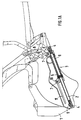
- Figure 1a is a side view of a top storage 1 with the attached components of the top linkage shown, the folding top is in the closed position.
- the piston rod 2 of a working cylinder 3 is attached to the top storage 1 at both ends 4.
- the piston 5 is centered on the Piston rod 2 attached.
- the one sliding on the stationary piston rod 2 Cylinder 6 is at one end 7 with a on the convertible top linkage acting drive lever 8 connected.
- the working cylinder 3 for opening and closing the convertible top is as double-acting cylinder 6, i.e. it acts on the convertible top linkage in both the opening and the shooting movement.
- the pressure oil supply line takes place at both ends 4 of the piston rod 2.
- Through holes 9 in the Piston rod 2 is the pressure oil in the respective cylinder space of the Working cylinder 3 passed.
- the folding top including those attached to the top storage 1 Working cylinders 3 pre-assembled as a finished unit and then on the Vehicle body attached.
- the pressure oil supply line is via rigid ends 4 of the piston rod 2 fixed lines.
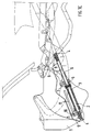
- Figure 1b shows a side view of a top storage 1 with the attached components of the top linkage and the top in half open Position.
- the pressure oil supply was via the left end 4 of the piston rod 2, to move from the closed to the half-open position of the convertible top reach.
- Figure 1c shows a side view of the top in the fully open position.
- the convertible top is opened by a pressure oil supply line on the right End 4 of the piston rod 2, this pressure oil supply line causes the cylinder 6 moves to the right, the closing by a pressure oil supply line over the left end 4 of the piston rod 2 and a displacement of the cylinder 6 to the left.
Landscapes
- Engineering & Computer Science (AREA)
- Mechanical Engineering (AREA)
- Actuator (AREA)
- Power-Operated Mechanisms For Wings (AREA)
- Superstructure Of Vehicle (AREA)
Description
- Fig.1a
- eine Seitenansicht der Verdeck-Betätigungsvorrichtung bei geschlossenem Verdeck,
- Fig.1b
- eine Seitenansicht der Verdeck-Betätigungsvorrichtung bei halbgeöffnetem Verdeck und
- Fig.1c
- eine Seitenansicht der Verdeck-Betätigungsvorrichtung bei geöffnetem Verdeck.
- 1
- Verdecklager
- 2
- Kolbenstange
- 3
- Arbeitszylinder (Kolbenstange 2 und Zylinder 6)
- 4
- Enden (der Kolbenstange)
- 5
- Kolben
- 6
- Zylinder
- 7
- Enden (des Zylinders)
- 8
- Antriebshebel
- 9
- Bohrungen
- 10
- Bolzen
- 11
- Führung
Claims (7)
- Verdeck für ein Fahrzeug, insbesondere Kraftfahrzeug, mit einem an aufbauseitig angeordneten Verdecklagern (1) schwenkbar gelagerten Verdeckgestänge, wobei zur Unterstützung der Öffnungs- und Schließbewegung des Verdecks am Verdeckgestänge benachbart, zumindest eines Verdecklagers (1) ein aus einem Zylinder (6) und einer Kolbenstange (2) zusammengesetzter Arbeitszylinder (3) angreift, dadurch gekennzeichnet, daß beide Enden (4) der Kolbenstange (2) des Arbeitszylinders (3) ortsfest am Verdecklager (1) befestigt sind und der beweglich auf der Kolbenstange (2) angeordnete Zylinder (6) mit einem, das Faltverdeck öffnenden und schließenden Antriebshebel (8) in Wirkverbindung steht und die Druckölzuleitung zum Arbeitszylinder (3) durch Bohrungen (9) in der stationären Kolbenstange (2) erfolgt.
- Verdeck nach Anspruch 1, dadurch gekennzeichnet, daß der Arbeitszylinder (3) als doppelt wirkender Zylinder (6) ausgebildet ist.
- Verdeck nach Anspruch 1, dadurch gekennzeichnet, daß der Kolben (5) mittig an der Kolbenstange (2) angebracht ist und die Druckölzuleitung wechselweise von beiden Enden (4) der Kolbenstange (2) durch die Bohrungen (9) erfolgt.
- Verdeck nach Anspruch 1, dadurch gekennzeichnet, daß die Anbindung des Antriebshebel (8) mittig an einem Zylinderende (7) angebracht ist.
- Verdeck nach Anspruch 1, dadurch gekennzeichnet, daß die Anbindung des Antriebshebel (8) außermittig an einem Zylinderende (7) angebracht ist und am anderen Ende (7) des Zylinders (6) eine Verdrehsicherung vorgesehen ist.
- Verdeck nach Anspruch 5, dadurch gekennzeichnet, daß die Verdrehsicherung aus einem am Zylinderende (7) angebrachten Bolzen (10) besteht, der in einer Führung (11) des Verdecklagers (1) gleitet.
- Verdeck nach den Ansprüchen 1 bis 6, dadurch gekennzeichnet, daß an jedem Verdecklager (1) ein Arbeitszylinder (3) angebracht ist.
Applications Claiming Priority (2)
| Application Number | Priority Date | Filing Date | Title |
|---|---|---|---|
| DE4438925 | 1994-10-31 | ||
| DE4438925A DE4438925C1 (de) | 1994-10-31 | 1994-10-31 | Verdeck für ein Fahrzeug, insbesondere Kraftfahrzeug |
Publications (2)
| Publication Number | Publication Date |
|---|---|
| EP0709243A1 EP0709243A1 (de) | 1996-05-01 |
| EP0709243B1 true EP0709243B1 (de) | 1998-12-16 |
Family
ID=6532167
Family Applications (1)
| Application Number | Title | Priority Date | Filing Date |
|---|---|---|---|
| EP95113449A Expired - Lifetime EP0709243B1 (de) | 1994-10-31 | 1995-08-28 | Verdeck für ein Fahrzeug, insbesondere Kraftfahrzeug |
Country Status (4)
| Country | Link |
|---|---|
| US (1) | US6536830B1 (de) |
| EP (1) | EP0709243B1 (de) |
| JP (1) | JP3642842B2 (de) |
| DE (2) | DE4438925C1 (de) |
Families Citing this family (8)
| Publication number | Priority date | Publication date | Assignee | Title |
|---|---|---|---|---|
| USRE38546E1 (en) * | 1993-01-04 | 2004-07-06 | Asc Incorporated | Convertible top |
| US5429409A (en) * | 1993-01-04 | 1995-07-04 | Asc Incorporated | Convertible top |
| DE19642153A1 (de) * | 1996-10-12 | 1998-04-16 | Karmann Gmbh W | Kraftfahrzeug mit einem versenkbaren Dach |
| NL1008656C2 (nl) * | 1998-03-20 | 1999-09-21 | Applied Power Inc | Hydraulische aandrijfcilinder. |
| FR2889155B1 (fr) * | 2005-07-28 | 2012-08-10 | Heuliez | Procede de montage d'un toit sur un vehicule convertible et vehicule correspondant |
| DE102005061201B3 (de) * | 2005-12-19 | 2007-04-05 | Rausch & Pausch Gmbh | Cabriosystem mit zwei im geschlossenen Zustand hintereinander angeordneten starren Dachteilen |
| DE102006042202B4 (de) | 2006-09-08 | 2024-08-08 | Dr. Ing. H.C. F. Porsche Aktiengesellschaft | Verdeckantrieb |
| US20230264547A1 (en) * | 2022-02-18 | 2023-08-24 | Bestop, Inc. | Pivotal soft top cover with lift assist |
Family Cites Families (6)
| Publication number | Priority date | Publication date | Assignee | Title |
|---|---|---|---|---|
| US2323547A (en) * | 1942-02-06 | 1943-07-06 | Jacobs Co F L | Foldable top structure |
| US2550925A (en) * | 1948-06-10 | 1951-05-01 | Brown & Sharpe Mfg | Means for blocking the bore of a long hollow piston rod |
| NL78765C (de) * | 1950-08-26 | |||
| DE3525375A1 (de) * | 1985-07-16 | 1987-01-22 | Jun Josef Goellner | Antriebs-zylinder-anordnung fuer stellbewegungen |
| JP2762089B2 (ja) * | 1989-01-13 | 1998-06-04 | 曙ブレーキ工業株式会社 | 三位置位置決め油圧シリンダー |
| DE3933624A1 (de) * | 1989-10-07 | 1991-04-11 | Hemscheidt Maschf Hermann | Zylinder-kolbenvorrichtung, insbesondere fuer die verwendung als stossdaempfer |
-
1994
- 1994-10-31 DE DE4438925A patent/DE4438925C1/de not_active Expired - Fee Related
-
1995
- 1995-08-28 DE DE59504551T patent/DE59504551D1/de not_active Expired - Lifetime
- 1995-08-28 EP EP95113449A patent/EP0709243B1/de not_active Expired - Lifetime
- 1995-10-24 JP JP27591595A patent/JP3642842B2/ja not_active Expired - Fee Related
- 1995-10-27 US US08/549,074 patent/US6536830B1/en not_active Expired - Fee Related
Also Published As
| Publication number | Publication date |
|---|---|
| DE4438925C1 (de) | 1995-11-09 |
| EP0709243A1 (de) | 1996-05-01 |
| US6536830B1 (en) | 2003-03-25 |
| DE59504551D1 (de) | 1999-01-28 |
| JP3642842B2 (ja) | 2005-04-27 |
| JPH08207592A (ja) | 1996-08-13 |
Similar Documents
| Publication | Publication Date | Title |
|---|---|---|
| EP0811518B2 (de) | Fahrzeug, insbesondere mit einem einklappbarem Dach | |
| DE10144583B4 (de) | Verdeck für ein Cabrioletfahrzeug | |
| DE19758130A1 (de) | Hubaggregat, insbesondere für einen gegenüber einem festen Teil schwenkbaren Deckel | |
| DE10108493A1 (de) | Antriebsvorrichtung für ein Klappverdeck | |
| DE4438925C1 (de) | Verdeck für ein Fahrzeug, insbesondere Kraftfahrzeug | |
| EP1279541B1 (de) | Verfahren und Vorrichtung zur Betätigung eines Verdecksystems bei Fahrzeugen | |
| DE1531204B2 (de) | Hydraulischer Greifer | |
| DE3400753A1 (de) | Aussenschwingtuer fuer fahrzeuge und ihre betaetigungsvorrichtung | |
| DE2130948A1 (de) | Erdbewegungsfahrzeug | |
| DE102005005237B3 (de) | Anordnung zum Schwenken der Teile eines Fahrzeugverdecks | |
| DE102004038221B4 (de) | Verdeck für ein Cabriolet-Fahrzeug | |
| DE3017729A1 (de) | Zweifluegelige seitenwand fuer kastenaufbauten bei nutzfahrzeugen o.dgl. | |
| DE10344648B4 (de) | Hydraulische Betätigungsanordnung | |
| DE69005408T2 (de) | Schranke mit symmetrischem Antrieb. | |
| EP1084886A2 (de) | Cabriolet-Fahrzeug | |
| EP0893605A1 (de) | "Hydraulische Betätigungsanordnung" | |
| DE869159C (de) | Klappverdeck fuer Kraftfahrzeuge | |
| DE10300837A1 (de) | Antriebsanordnung für einen schwenkbaren Fahrzeugscheibenwischer | |
| EP2125411A2 (de) | Öffnungsfähiges fahrzeugdach mit einer viergelenkanordnung | |
| DE2455227A1 (de) | Hebebuehne, insbesondere ladebordwand fuer kraftfahrzeuge | |
| DE10036922C1 (de) | Hauptlagereinheit für ein Cabrio-Verdeck | |
| DE2618179A1 (de) | Falttor mit gelenkantrieb | |
| DE10111705A1 (de) | Betätigungsanordnung für schwenkbare Teile an Fahrzeugen | |
| DE102005061201B3 (de) | Cabriosystem mit zwei im geschlossenen Zustand hintereinander angeordneten starren Dachteilen | |
| EP1897734B1 (de) | Cabriolet |
Legal Events
| Date | Code | Title | Description |
|---|---|---|---|
| PUAI | Public reference made under article 153(3) epc to a published international application that has entered the european phase |
Free format text: ORIGINAL CODE: 0009012 |
|
| AK | Designated contracting states |
Kind code of ref document: A1 Designated state(s): DE FR GB IT |
|
| 17P | Request for examination filed |
Effective date: 19961009 |
|
| 17Q | First examination report despatched |
Effective date: 19971114 |
|
| GRAG | Despatch of communication of intention to grant |
Free format text: ORIGINAL CODE: EPIDOS AGRA |
|
| GRAG | Despatch of communication of intention to grant |
Free format text: ORIGINAL CODE: EPIDOS AGRA |
|
| GRAH | Despatch of communication of intention to grant a patent |
Free format text: ORIGINAL CODE: EPIDOS IGRA |
|
| ITF | It: translation for a ep patent filed | ||
| GRAH | Despatch of communication of intention to grant a patent |
Free format text: ORIGINAL CODE: EPIDOS IGRA |
|
| GRAA | (expected) grant |
Free format text: ORIGINAL CODE: 0009210 |
|
| AK | Designated contracting states |
Kind code of ref document: B1 Designated state(s): DE FR GB IT |
|
| GBT | Gb: translation of ep patent filed (gb section 77(6)(a)/1977) |
Effective date: 19981221 |
|
| REF | Corresponds to: |
Ref document number: 59504551 Country of ref document: DE Date of ref document: 19990128 |
|
| ET | Fr: translation filed | ||
| PLBE | No opposition filed within time limit |
Free format text: ORIGINAL CODE: 0009261 |
|
| STAA | Information on the status of an ep patent application or granted ep patent |
Free format text: STATUS: NO OPPOSITION FILED WITHIN TIME LIMIT |
|
| 26N | No opposition filed | ||
| REG | Reference to a national code |
Ref country code: GB Ref legal event code: IF02 |
|
| PGFP | Annual fee paid to national office [announced via postgrant information from national office to epo] |
Ref country code: IT Payment date: 20080826 Year of fee payment: 14 Ref country code: FR Payment date: 20080813 Year of fee payment: 14 |
|
| PGFP | Annual fee paid to national office [announced via postgrant information from national office to epo] |
Ref country code: GB Payment date: 20080821 Year of fee payment: 14 |
|
| REG | Reference to a national code |
Ref country code: FR Ref legal event code: TP |
|
| REG | Reference to a national code |
Ref country code: FR Ref legal event code: CD |
|
| GBPC | Gb: european patent ceased through non-payment of renewal fee |
Effective date: 20090828 |
|
| REG | Reference to a national code |
Ref country code: FR Ref legal event code: ST Effective date: 20100430 |
|
| PG25 | Lapsed in a contracting state [announced via postgrant information from national office to epo] |
Ref country code: FR Free format text: LAPSE BECAUSE OF NON-PAYMENT OF DUE FEES Effective date: 20090831 |
|
| PG25 | Lapsed in a contracting state [announced via postgrant information from national office to epo] |
Ref country code: GB Free format text: LAPSE BECAUSE OF NON-PAYMENT OF DUE FEES Effective date: 20090828 |
|
| PGFP | Annual fee paid to national office [announced via postgrant information from national office to epo] |
Ref country code: DE Payment date: 20100809 Year of fee payment: 16 |
|
| PG25 | Lapsed in a contracting state [announced via postgrant information from national office to epo] |
Ref country code: IT Free format text: LAPSE BECAUSE OF NON-PAYMENT OF DUE FEES Effective date: 20090828 |
|
| REG | Reference to a national code |
Ref country code: DE Ref legal event code: R119 Ref document number: 59504551 Country of ref document: DE Effective date: 20120301 |
|
| PG25 | Lapsed in a contracting state [announced via postgrant information from national office to epo] |
Ref country code: DE Free format text: LAPSE BECAUSE OF NON-PAYMENT OF DUE FEES Effective date: 20120301 |