EP0709192A2 - Verfahren und Vorrichtung zur Korrektur eines Druckkopfes, mittels dieser Vorrichtung korrigierter Druckkopf und diesen Druckkopf verwendende Druckvorrichtung - Google Patents
Verfahren und Vorrichtung zur Korrektur eines Druckkopfes, mittels dieser Vorrichtung korrigierter Druckkopf und diesen Druckkopf verwendende Druckvorrichtung Download PDFInfo
- Publication number
- EP0709192A2 EP0709192A2 EP95307600A EP95307600A EP0709192A2 EP 0709192 A2 EP0709192 A2 EP 0709192A2 EP 95307600 A EP95307600 A EP 95307600A EP 95307600 A EP95307600 A EP 95307600A EP 0709192 A2 EP0709192 A2 EP 0709192A2
- Authority
- EP
- European Patent Office
- Prior art keywords
- printhead
- printing
- data
- correction
- pixels
- Prior art date
- Legal status (The legal status is an assumption and is not a legal conclusion. Google has not performed a legal analysis and makes no representation as to the accuracy of the status listed.)
- Granted
Links
Images


Classifications
-
- B—PERFORMING OPERATIONS; TRANSPORTING
- B41—PRINTING; LINING MACHINES; TYPEWRITERS; STAMPS
- B41J—TYPEWRITERS; SELECTIVE PRINTING MECHANISMS, i.e. MECHANISMS PRINTING OTHERWISE THAN FROM A FORME; CORRECTION OF TYPOGRAPHICAL ERRORS
- B41J2/00—Typewriters or selective printing mechanisms characterised by the printing or marking process for which they are designed
- B41J2/005—Typewriters or selective printing mechanisms characterised by the printing or marking process for which they are designed characterised by bringing liquid or particles selectively into contact with a printing material
- B41J2/01—Ink jet
- B41J2/015—Ink jet characterised by the jet generation process
- B41J2/04—Ink jet characterised by the jet generation process generating single droplets or particles on demand
- B41J2/045—Ink jet characterised by the jet generation process generating single droplets or particles on demand by pressure, e.g. electromechanical transducers
- B41J2/04501—Control methods or devices therefor, e.g. driver circuits, control circuits
- B41J2/04506—Control methods or devices therefor, e.g. driver circuits, control circuits aiming at correcting manufacturing tolerances
-
- B—PERFORMING OPERATIONS; TRANSPORTING
- B41—PRINTING; LINING MACHINES; TYPEWRITERS; STAMPS
- B41J—TYPEWRITERS; SELECTIVE PRINTING MECHANISMS, i.e. MECHANISMS PRINTING OTHERWISE THAN FROM A FORME; CORRECTION OF TYPOGRAPHICAL ERRORS
- B41J2/00—Typewriters or selective printing mechanisms characterised by the printing or marking process for which they are designed
- B41J2/005—Typewriters or selective printing mechanisms characterised by the printing or marking process for which they are designed characterised by bringing liquid or particles selectively into contact with a printing material
- B41J2/01—Ink jet
- B41J2/015—Ink jet characterised by the jet generation process
- B41J2/04—Ink jet characterised by the jet generation process generating single droplets or particles on demand
- B41J2/045—Ink jet characterised by the jet generation process generating single droplets or particles on demand by pressure, e.g. electromechanical transducers
- B41J2/04501—Control methods or devices therefor, e.g. driver circuits, control circuits
- B41J2/04541—Specific driving circuit
-
- B—PERFORMING OPERATIONS; TRANSPORTING
- B41—PRINTING; LINING MACHINES; TYPEWRITERS; STAMPS
- B41J—TYPEWRITERS; SELECTIVE PRINTING MECHANISMS, i.e. MECHANISMS PRINTING OTHERWISE THAN FROM A FORME; CORRECTION OF TYPOGRAPHICAL ERRORS
- B41J2/00—Typewriters or selective printing mechanisms characterised by the printing or marking process for which they are designed
- B41J2/005—Typewriters or selective printing mechanisms characterised by the printing or marking process for which they are designed characterised by bringing liquid or particles selectively into contact with a printing material
- B41J2/01—Ink jet
- B41J2/015—Ink jet characterised by the jet generation process
- B41J2/04—Ink jet characterised by the jet generation process generating single droplets or particles on demand
- B41J2/045—Ink jet characterised by the jet generation process generating single droplets or particles on demand by pressure, e.g. electromechanical transducers
- B41J2/04501—Control methods or devices therefor, e.g. driver circuits, control circuits
- B41J2/04543—Block driving
-
- B—PERFORMING OPERATIONS; TRANSPORTING
- B41—PRINTING; LINING MACHINES; TYPEWRITERS; STAMPS
- B41J—TYPEWRITERS; SELECTIVE PRINTING MECHANISMS, i.e. MECHANISMS PRINTING OTHERWISE THAN FROM A FORME; CORRECTION OF TYPOGRAPHICAL ERRORS
- B41J2/00—Typewriters or selective printing mechanisms characterised by the printing or marking process for which they are designed
- B41J2/005—Typewriters or selective printing mechanisms characterised by the printing or marking process for which they are designed characterised by bringing liquid or particles selectively into contact with a printing material
- B41J2/01—Ink jet
- B41J2/015—Ink jet characterised by the jet generation process
- B41J2/04—Ink jet characterised by the jet generation process generating single droplets or particles on demand
- B41J2/045—Ink jet characterised by the jet generation process generating single droplets or particles on demand by pressure, e.g. electromechanical transducers
- B41J2/04501—Control methods or devices therefor, e.g. driver circuits, control circuits
- B41J2/04563—Control methods or devices therefor, e.g. driver circuits, control circuits detecting head temperature; Ink temperature
-
- B—PERFORMING OPERATIONS; TRANSPORTING
- B41—PRINTING; LINING MACHINES; TYPEWRITERS; STAMPS
- B41J—TYPEWRITERS; SELECTIVE PRINTING MECHANISMS, i.e. MECHANISMS PRINTING OTHERWISE THAN FROM A FORME; CORRECTION OF TYPOGRAPHICAL ERRORS
- B41J2/00—Typewriters or selective printing mechanisms characterised by the printing or marking process for which they are designed
- B41J2/005—Typewriters or selective printing mechanisms characterised by the printing or marking process for which they are designed characterised by bringing liquid or particles selectively into contact with a printing material
- B41J2/01—Ink jet
- B41J2/015—Ink jet characterised by the jet generation process
- B41J2/04—Ink jet characterised by the jet generation process generating single droplets or particles on demand
- B41J2/045—Ink jet characterised by the jet generation process generating single droplets or particles on demand by pressure, e.g. electromechanical transducers
- B41J2/04501—Control methods or devices therefor, e.g. driver circuits, control circuits
- B41J2/04565—Control methods or devices therefor, e.g. driver circuits, control circuits detecting heater resistance
-
- B—PERFORMING OPERATIONS; TRANSPORTING
- B41—PRINTING; LINING MACHINES; TYPEWRITERS; STAMPS
- B41J—TYPEWRITERS; SELECTIVE PRINTING MECHANISMS, i.e. MECHANISMS PRINTING OTHERWISE THAN FROM A FORME; CORRECTION OF TYPOGRAPHICAL ERRORS
- B41J2/00—Typewriters or selective printing mechanisms characterised by the printing or marking process for which they are designed
- B41J2/005—Typewriters or selective printing mechanisms characterised by the printing or marking process for which they are designed characterised by bringing liquid or particles selectively into contact with a printing material
- B41J2/01—Ink jet
- B41J2/015—Ink jet characterised by the jet generation process
- B41J2/04—Ink jet characterised by the jet generation process generating single droplets or particles on demand
- B41J2/045—Ink jet characterised by the jet generation process generating single droplets or particles on demand by pressure, e.g. electromechanical transducers
- B41J2/04501—Control methods or devices therefor, e.g. driver circuits, control circuits
- B41J2/0458—Control methods or devices therefor, e.g. driver circuits, control circuits controlling heads based on heating elements forming bubbles
-
- B—PERFORMING OPERATIONS; TRANSPORTING
- B41—PRINTING; LINING MACHINES; TYPEWRITERS; STAMPS
- B41J—TYPEWRITERS; SELECTIVE PRINTING MECHANISMS, i.e. MECHANISMS PRINTING OTHERWISE THAN FROM A FORME; CORRECTION OF TYPOGRAPHICAL ERRORS
- B41J2/00—Typewriters or selective printing mechanisms characterised by the printing or marking process for which they are designed
- B41J2/005—Typewriters or selective printing mechanisms characterised by the printing or marking process for which they are designed characterised by bringing liquid or particles selectively into contact with a printing material
- B41J2/01—Ink jet
- B41J2/015—Ink jet characterised by the jet generation process
- B41J2/04—Ink jet characterised by the jet generation process generating single droplets or particles on demand
- B41J2/045—Ink jet characterised by the jet generation process generating single droplets or particles on demand by pressure, e.g. electromechanical transducers
- B41J2/04501—Control methods or devices therefor, e.g. driver circuits, control circuits
- B41J2/04588—Control methods or devices therefor, e.g. driver circuits, control circuits using a specific waveform
-
- B—PERFORMING OPERATIONS; TRANSPORTING
- B41—PRINTING; LINING MACHINES; TYPEWRITERS; STAMPS
- B41J—TYPEWRITERS; SELECTIVE PRINTING MECHANISMS, i.e. MECHANISMS PRINTING OTHERWISE THAN FROM A FORME; CORRECTION OF TYPOGRAPHICAL ERRORS
- B41J2/00—Typewriters or selective printing mechanisms characterised by the printing or marking process for which they are designed
- B41J2/005—Typewriters or selective printing mechanisms characterised by the printing or marking process for which they are designed characterised by bringing liquid or particles selectively into contact with a printing material
- B41J2/01—Ink jet
- B41J2/015—Ink jet characterised by the jet generation process
- B41J2/04—Ink jet characterised by the jet generation process generating single droplets or particles on demand
- B41J2/045—Ink jet characterised by the jet generation process generating single droplets or particles on demand by pressure, e.g. electromechanical transducers
- B41J2/04501—Control methods or devices therefor, e.g. driver circuits, control circuits
- B41J2/04591—Width of the driving signal being adjusted
-
- B—PERFORMING OPERATIONS; TRANSPORTING
- B41—PRINTING; LINING MACHINES; TYPEWRITERS; STAMPS
- B41J—TYPEWRITERS; SELECTIVE PRINTING MECHANISMS, i.e. MECHANISMS PRINTING OTHERWISE THAN FROM A FORME; CORRECTION OF TYPOGRAPHICAL ERRORS
- B41J2/00—Typewriters or selective printing mechanisms characterised by the printing or marking process for which they are designed
- B41J2/005—Typewriters or selective printing mechanisms characterised by the printing or marking process for which they are designed characterised by bringing liquid or particles selectively into contact with a printing material
- B41J2/01—Ink jet
- B41J2/015—Ink jet characterised by the jet generation process
- B41J2/04—Ink jet characterised by the jet generation process generating single droplets or particles on demand
- B41J2/045—Ink jet characterised by the jet generation process generating single droplets or particles on demand by pressure, e.g. electromechanical transducers
- B41J2/04501—Control methods or devices therefor, e.g. driver circuits, control circuits
- B41J2/04598—Pre-pulse
Definitions
- This invention relates to a method and apparatus for correcting a printhead, a printhead corrected by this apparatus, and a printing apparatus using this printhead. More particularly, the invention relates to a method and apparatus for correcting, by way of example, a full-line printhead equipped with a plurality of printing elements corresponding to the printing width of a recording medium, a printhead corrected by this apparatus, and a printing apparatus using this printhead.
- a printer or the printing section of a copying machine or facsimile machine is so adapted as to print an image, which comprises a dot pattern, on a recording medium such as a paper, a thin plastic sheet or fabric based upon image information.
- the printing elements can be formed through a process similar to a semiconductor manufacturing process. Accordingly, a transition is now being made from a configuration in which the printhead and driving integrated circuitry are arranged separately of each other to an integrated assembled configuration in which the driving integrated circuitry is structurally integrated within the same base on which the printing elements are arrayed. As a result, complicated circuitry involved in driving the printhead can be avoided and the printing apparatus can be reduced in size and cost.
- the ink-jet printing method is particularly advantageous. Specifically, according to this method, thermal energy is made to act upon ink and the ink is discharged by utilizing the pressure produced by thermal expansion. This method is advantageous in that the response to a printing signal is good and it is easy to group the orifices close together at a high density. There are greater expectations for this method in comparison with the other methods.
- the printhead When the printhead is manufactured by applying a semiconductor manufacturing process and, in particular, when numerous printing elements that are to be made to correspond to the printing width are arrayed over the entire area of a base, it is very difficult to manufacture all of the printing elements without any defects. As a consequence, the manufacturing yield of the process for manufacturing the printhead is poor and this is accompanied by higher cost. There are occasions where such a printhead cannot be put into practical use because of the costs involved.
- an object of the present invention is to provide an apparatus and method for correcting a manufactured printhead, wherein it is possible to realize a printhead at low cost and high yield without subjecting the printhead to a much load and without inviting a decline in printing quality, such as a decline in quality caused by visible density unevenness.
- an apparatus for correcting a printing characteristic of a printhead having a plurality of printing elements and memory means for storing data comprising printhead drive means for driving the printhead to perform experimental printing on a recording medium, detecting means for detecting, based on an image that has been printed on the recording medium, a variation in density per a plurality of pixels selected upon taking human visual discriminating ability into account, correction-data generating means for generating, per the plurality of printing elements, correction data for correcting the variation in density detected by said detecting means, and writing means for writing the correction data in said memory means of the printhead.
- the detecting means in the apparatus includes reading means for reading the recorded image, image processing means for processing an image signal representing the image read by the reading means, counting means for counting the number of black pixels or white pixels per the plurality of pixels from the image signal that has been subjected to image processing, and binarizing means for comparing the number of black pixels or white pixels obtained by the counting means with a predetermined threshold value, thereby binarizing the number of black pixels or white pixels, and the correction-data generating means generates the correction data based upon the binarized value.
- the foregoing object is attained by providing a method of correcting a printing characteristic of a printhead having a plurality of printing elements and a memory unit for storing data, said method comprising a testing step of performing experimental printing on a recording medium using the printhead, a detecting step of detecting, based on an image that has been printed on the recording medium, a variation in density per a plurality of pixels selected upon taking human visual discriminating ability into account, a correction-data generating step of generating, per the plurality of printing elements, correction data for correcting the variance in density detected in said detecting step, and a writing step of writing the correction data in the memory unit of the printhead.
- a printhead having a plurality of printing elements and memory means capable of storing information is mounted, experimental printing is performed on a recording medium, a variation in density per a plurality of pixels selected upon considering human visual discriminating ability is detected from the image printed on the recording medium, correction data for correcting the detected variation in density is generated per the plurality of printing elements and this correction data is transmitted to the memory means possessed by the printhead.
- Another object of the present invention is to provide the above-mentioned printhead and a printing apparatus using the printhead.
- the foregoing object is attained by providing a printhead corrected by the above-described printhead correction apparatus.
- the printhead has input means for inputting printing data from an external unit, and drive means for driving the plurality of printing elements based upon the printing data inputted by the input means.
- the foregoing object is attained by providing a printing apparatus using the above-described printhead, comprising receiving means for receiving the correction data from the printhead, control means which, on the basis of the correction data, generates a control signal for controlling operation of the drive means in such a manner that the printing elements form uniform pixels, and transmitting means for transmitting the control signal to the printhead.
- the control signal in this printing apparatus includes a first pulse signal and a second pulse signal that follows the first pulse signal, and the control means adjusts the width of the first pulse signal, the width of the second pulse signal and the pulse interval between the first and second pulse signals, based on the correction data.
- the printhead corrected as set forth above is mounted on a printing apparatus, the correction data that has been stored in the memory means of the printhead is received, a control signal is generated on the basis of the correction data to control the operation of the drive means, with which the printhead is provided, in such a manner that the plurality of printing elements of the printhead form uniform pixels, and the control signal is sent to the printhead.
- control signal includes the first pulse signal and the second pulse signal that follows the first pulse signal, and the width of the first pulse signal, the width of the second pulse signal and the pulse interval between the first and second pulse signals are adjusted in the printing apparatus on the basis of the correction data received from the printhead.
- a printhead having a plurality of printing elements and memory means capable of storing information is mounted, experimental printing is performed on a recording medium, a variation in density per a plurality of pixels selected upon considering human visual discriminating ability is detected from the image printed on the recording medium, correction data for correcting the detected variation in density is generated per the plurality of printing elements and this correction data is transmitted to the memory means possessed by the printhead.
- the invention is particularly advantageous in that it is possible to correct, in simple fashion, a printhead at low cost and high yield without complicating the manufacturing process and without inviting a decline in printing quality, such as a decline in quality caused by visible density unevenness.
- the invention is effective in that a variation in printing density ascribable to the printing elements is eliminated.
- a printing apparatus mounted with the printhead corrected as set forth above is such that the correction data that has been stored in the memory means of the printhead is received, a control signal is generated on the basis of the correction data to control the operation of the drive means, with which the printhead is provided, in such a manner that the plurality of printing elements of the printhead form uniform pixels, and the control signal is sent to the printhead.
- an advantage of the invention is that it is possible to perform high-quality printing without visible density unevenness.
- control signal includes the first pulse signal and the second pulse signal that follows the first pulse signal, and the width of the first pulse signal, the width of the second pulse signal and the pulse interval between the first and second pulse signals are adjusted in the printing apparatus on the basis of the correction data received from the printhead.
- Fig. 1 is an external perspective view showing the principal portions of an ink-jet printer IJRA, which is a typical embodiment of the present invention.
- the printer has a printhead (a full-length multiple printhead) IJH arranged along a range of full width of recording paper (a continuous sheet) P.
- the printhead IJH discharges ink over a range extending across the full width of the recording paper P.
- the ink is discharged toward the recording paper P from an orifice IT of the printhead at a prescribed timing.
- the continuous sheet of foldable recording paper P is conveyed in the direction VS in Fig. 1 by driving a conveying motor under the control of a control circuit, described below.
- An image is printed on the recording paper.
- the printer in Fig. 1 further includes sheet feeding rollers 5018 and discharge rollers 5019.
- the discharge rollers 5019 cooperate with the sheet feeding rollers 5018 to hold the continuous sheet of recording paper P at the printing position and operate in association with the sheet feeding rollers 5018, which are driven by a drive motor (not shown), to feed the recording paper P in the direction of arrow VS.
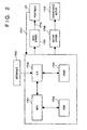
- Fig. 2 is a block diagram illustrating the construction of the control circuit of the ink-jet printer. Shown in Fig. 2 are an interface 1700 for entering a printing signal from an external device such as a host computer, an MPU 1701, a ROM 1702 for storing a control program (inclusive of character fonts as necessary) executed by the MPU 1701, a DRAM 1703 for temporarily saving various data (the above-mentioned printing signal and printing data that is supplied to the printhead), and a gate array (G.A.) 1704 for controlling supply of printing data to the printhead IJH.
- the gate array 1704 also controls transfer of data among the interface 1700, MPU 1701 and RAM 1703. Also shown are a conveyance motor 1708 for conveying recording paper (the continuous sheet in this embodiment), a head driver 1705 for driving the printhead, and a motor driver 1706 for driving the conveyance motor 1708.
- the printing signal enters the interface 1700, whereupon the printing signal is converted to printing data for printing between the gate array 1704 and MPU 1701.
- the motor driver 1706 is driven into operation and the printhead IJH is driven in accordance with the printing data sent to the head driver 1705. As a result, a printing operation is carried out.
- Numeral 1711 denotes a signal line for monitoring sensors (e.g., a heating-resistor sensor 314 and a temperature sensor 315, which are shown in Fig. 11) of each board, and for transmitting correction data from a memory 13 (described later) storing correction data which corrects for a variation in each board (heater board 1000, described later) provided within the printhead IJH.
- Numeral 1712 denotes a signal line for carrying preheating pulses, latch signals and heating pulses.
- the MPU 1701 sends the printhead IJH a control signal via the signal line 1712 in such a manner that the boards are capable of forming uniform pixels.
- Fig. 3 is a block diagram illustrating the construction of the printhead correction apparatus of this embodiment.
- An I/O interface 2 interfaces the CPU 1 with the various controllers of the apparatus.
- An image processor 3 uses a CCD camera 4 to read the printing dot pattern on a recording medium placed upon a paper feeding stage 5 and converts the dot diameter and density unevenness of the dot pattern to pixel values.
- the dot data corresponding to all printing elements of the printhead IJH is sent from the image processor 3 to the CPU 1, the latter operates upon the dot data, sends density correction data to a driving signal controller 7 in conformity with a drive signal for driving the printhead IJH and causes a memory controller 8 to develop the density correction data.
- An image data controller 6 outputs a dot pattern to be recorded to the printhead IJH.
- the controller 6 transmits a density correction drive signal while sending a synchronizing signal to the drive signal controller 7 not only at the time of ordinary printing but also when the density correction data has been determined.
- the CPU 1 manages a head voltage controller 9 which controls the driving voltage of the printhead IJH and manages a stage/paper-feed controller 11 for controlling the operation of the paper feeding stage 5, thereby setting a proper drive voltage and controlling stage movement and paper feed.
- a head data detector 10 is an important component which feeds back, for the purpose of density correction, the characteristics of each board (printing unit) 1000 (see Fig. 7) within the printhead IJH.
- the printhead IJH which, by way of example, is composed of a row of a plurality boards 1000 on which 64 or 128 printing elements have been disposed, it is not known from which portions of a silicon wafer or the like the boards 1000 have been cut. Accordingly, there are cases in which the characteristics differ from one board to another.
- a rank detecting resistor element RH having a surface resistivity ( ⁇ / ⁇ ) identical with that of the printing element is provided in each board 1000 in order that all printheads can perform printing at an uniform density.
- a semiconductor element capable of monitoring a change in temperature is provided for each board 1000.
- the head data detector 10 monitors these elements. When the head data detector 10 sends data obtained by monitoring these elements to the CPU 1, the latter generates correction data, which is for correcting the data that drives each of the boards 1000, in such a manner that each board 1000 in the printhead can print at a uniform density.
- the rank mentioned here is a parameter obtained by quantifying the characteristic of each board 1000. The parameter is expressed by a function of a surface resistivity ( ⁇ / ⁇ ).
- the printing operation by the printhead IJH is executed under these conditions.
- the results of printing are again subjected to image processing by the CCD camera 4 and image processor 3, and the memory controller 8 writes the final correction data in the memory 13 (a non-volatile memory such as an EEPROM) at a stage at which the predetermined criteria of the printhead is satisfied.
- the memory 13 a non-volatile memory such as an EEPROM
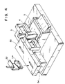
- Fig. 4 is an external perspective view showing the construction the printhead correction apparatus
- Fig. 5 is a flowchart illustrating the operation of the apparatus. Operation will now be described with reference to Figs. 4 and 5.
- the CPU 1 When the printhead IJH is inserted into a slot of a securing table 50, the CPU 1 operates the table 50 and fixes the printhead IJH to the table 50 in such a manner that the printhead IJH can perform printing at a normal position. At the same time, electrical contact is made with the printhead IJH, and an ink supply device 52 is connected to the printhead IJH (step S2). Next, in order to measure the rank of the printhead IJH, the a surface resistivity ( ⁇ / ⁇ ) of the substrate 1000 is monitored (step S4).
- a surface resistivity ( ⁇ / ⁇ ) of each block (of each board in a case where the block is constituted by an array of a plurality of boards) is monitored, driving power is decided separately for each board and a test pattern is recorded (step S6).
- preprocessing for printing the test pattern preliminary discharge (aging) is carried out until the operation of the printhead IJH stabilizes to enable stable printing by the printhead. Aging is performed on an aging tray juxtaposed on a head recovery processor 54, and recovery processing (ink suction, cleaning of orifice surfaces, etc.) is executed in such a manner that the test pattern can be printed normally.
- the result of printing is moved to the position of the CCD camera 4 and of the image processor 3, where the result of printing is subjected to image processing by these components and compared with parameters for printing evaluation. Processing is executed while taking the items mentioned below into account in relation to density unevenness of recording elements. Density unevenness is a parameter that can be improved.
- Density unevenness of an image is produced by a difference in relative density contrast in printing performed by printing elements.
- printing elements which produce a high-density printing are concentrated somewhat closely together in space, the occurrence of density unevenness becomes apparent.
- density unevenness data near the discriminating ability of the human eye can be created by (1) performing a density unevenness correction in units of several dots (two to eight pixels, depending upon printing density); and (2) increasing the number of events of image processing (the number of events per printed dot or the number of events in a group of printed dots (16 ⁇ 1024 dots)).
- Fig. 6 illustrates an example of an image pattern read by a CCD camera or the like.
- a dot pattern having a 50% duty is formed and a dot pattern of 32 dots ⁇ 32 dots is allocated to the screen area of the CCD camera.
- a and B are areas of 4 ⁇ 32 dots each. In this embodiment, each are is one event.
- C and D in Fig. 6 are disposed as markers for image recognition of the dot pattern of 32 ⁇ 32 dots.
- n represent the first dot read.
- the area A constituting one event is composed of a collection of 32 bits in the y direction (the direction in which the recording medium is conveyed) from n to n+3 in the x direction (the column direction of the printing elements). Eight similar areas are produced in an image memory (not shown), and binarizing processing is performed in each area in accordance with the number of "black” or "white” pixels in the area and a predetermined threshold value. It should be noted that an optimum value obtained experimentally is used as the threshold value. As the result of this binarizing processing, density unevenness data is obtained for every four dots in the x direction.
- an image having an area corresponding to more than 100 dots per one nozzle of a printing element can be read in and processed by an image scanner, wherein the dot pattern has the 50% duty shown in Fig. 6, and the processed results can be used as the density unevenness data.
- the density unevenness data thus obtained does not have a complicated structure and can be processed in a short period of time in both a printhead manufacturing apparatus and a printer.
- this embodiments can reduce the number of testing performed until it is determined at step S8 that the testing is OK, compared to U.S. Patent Application No. 08/397,352 filed on March 2, 1995.
- U.S. Patent Application No. 08/397,352 Japanese Patent Application No. 6-34558 discloses a method of correcting the unevenness in the density of a printhead by measuring dot diameter and correcting unevenness based upon the results of measurement.
- it is still necessary to improve reproducibility of printed dots For example, when one line of printing has been performed, the characteristics of the printed dots change subtly on the next line, over then next several dozen lines and over the next several hundred lines. (This is known as "fluctuation" from dot to dot.) Since a specific phenomenon (dot diameter) which incorporates this fluctuation is employed as information regarding density unevenness, satisfactory results are not obtained with a single correction.
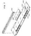
- Fig. 7 is an exploded perspective view for describing the construction of the printhead of this embodiment.
- the printing elements are elements for generating ink-discharge energy used to jet ink.
- each element comprises a pair of electrodes and a heating resistor element provided between these electrodes).
- the full-line printhead which is faultlessly fabricated over its entire width by a conventional photolithographic process or the like, is obtained at a very high yield.
- a single, unitary grooved member having a plurality of ink discharge orifices formed in one end and a plurality of grooves connected to these orifices and formed in the grooved member from one end to the other is joined to this printhead in such a manner that the grooves are closed by the boards, whereby a full-line, ink-jet printhead unit can be corrected in a very simple manner.
- the ink-jet printhead described in this embodiment has ink discharge orifices at a density of 360 dpi (70.5 ⁇ m), the number of nozzles thereof being 3008 (for a printing width of 212 mm).
- the board 1000 has 128 discharge-energy generating devices 1010 arranged at prescribed positions at a density of 360 dpi.
- Each heater board 1000 is provided with a signal pad to drive the discharge-energy generating devices 1010 at any timing by externally applied electric signals, and with a power pad 1020 for supplying an electric power for the driving.
- the row of the heater boards 1000 is fixedly bonded by a bonding agent to the surface of a base plate 3000 made of a material such as metal or ceramic.
- Fig. 8 is a detailed view showing the heater boards 1000 in the arrayed state.
- the heater boards are fixedly bonded to a prescribed location on the base plate 3000 by a bonding agent 3010 applied to a prescribed thickness.
- the gaps produced between adjacent heater boards 1000 are filled and sealed by a sealant 3020.
- a wiring board 4000 is fixedly bonded to the base plate 3000 in the same manner as the heater boards. At this time the wiring board 4000 is bonded to the base plate 3000 in a state in which the pads 1020 on the heater boards 1000 are in close proximity to signal-power supply pads 4010 provided on the wiring board 4000.
- a connector 4020 for receiving a printing signal and driving power from the outside is provided on the wiring board 4000.
- a grooved member 2000 will now be described.
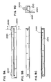
- Figs. 9A ⁇ 9D are diagrams showing the shape of the grooved member 2000.
- Fig. 9A is a front view in which the grooved member 2000 is seen from the front
- Fig. 9B a top view in which Fig. 9A is seen from the top
- Fig. 9C a bottom view in which Fig. 9A is seen from the bottom
- Fig. 9D a sectional view taken along line X-X of Fig. 9A.
- the grooved member 2000 is shown to have a flow pass 2020 provided to correspond to each discharge-energy generating element 1010 provided in the heater board 1000, an orifice 2030 corresponding to each flow pass 2020 and communicating with the flow pass 2020 for discharging ink toward the recording medium, a liquid chamber 2010 communicating with each flow pass 2020 in order to supply it with ink, and an ink supply port 2040 for feeding ink, which has been supplied from an ink tank (not shown), to the liquid chamber 2010.
- the grooved member 2000 naturally is formed to have a length large enough to substantially cover the row of discharge-energy generating devices arranged by lining up a plurality of the heater boards 1000.
- the grooved member 2000 is joined to the heater boards 1000 in a state in which the positions of the flow pass 2020 of the grooved member 2000 are made to exactly coincide with the positions of the discharge-energy generating elements (heaters) 1010 on the heater boards 1000 arranged in a row on the base plate 3000.
- Conceivable methods of joining the grooved member 2000 are a method in which the grooved member is pushed in mechanically using springs or the like, a method in which the grooved member 2000 is fixed by a bonding agent, and a method which is a combination of these methods.
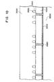
- the grooved member 2000 and each of the heater boards 1000 are secured in the relationship shown in Fig. 10 by any of these methods.
- the grooved member 2000 described above can be manufactured using well-known methods such as machining by cutting, a molding method, casting or a method relying upon photolithography.
- Fig. 11 shows an example of drive circuitry provided on the heater board 1000 of the printhead.
- Numeral 100 denotes a base, 101 a logic block for selecting preheating pulses, 303 a latch for temporarily storing image data, 102 a selection-data saving latch, having the same circuit arrangement as the latch 303, for selecting preheating pulses, and 103 an OR gate for taking the OR of heating pulses and preheating pulses.
- preheating pulses are selected dependence upon the characteristic of the amount of ink discharged (per application of a pulse at a fixed temperature).
- the characteristic is measured in advance.
- Data of each nozzle (the data is identical for four nozzles) for selecting the preheating pulses in dependence upon the aforesaid characteristic is saved in the selection-data saving latch 102 using a shift register 304 for entering image data serially. Since shared use is made of the shift register 304 for entering image data, it will suffice merely to increase the number of latch circuits and latch the outputs of the shift register 304 as input signals in parallel fashion, as shown at points a in Fig. 11.
- a characterizing feature of this board is that a heating input terminal 106 and a plurality of preheating input terminals 107a ⁇ 107h, which are used for changing the amount of ink discharged, are separately provided. First, a signal from the heating-resistor monitor 314 is fed back and a heating signal having a pulse width of an energy suited to discharge of ink in dependence upon the value of feedback is applied to the heating input terminal 106 from the side of the printing apparatus.
- the pulse width and timing of each of the plurality of preheating signals are changed in dependence upon the value from the temperature sensor 315 and, at the same time, preheating signals are applied from the plurality of preheating pulse terminals 107a ⁇ 107h in such a manner that the amount of ink discharged will vary under fixed temperature conditions.
- the amount of ink discharge can be rendered constant to eliminate unevenness and blurring.
- One of the plurality of preheating pulses thus entered is selected in dependence upon selection data saved in advance in the preheat selection logic block (latch) 102.
- an AND signal between the image data and heating signal is OR-ed with a selected preheating pulse by the OR gate 103, and the resulting signal drives a power transistor 302, thereby passing an electric current through the heater 1010 to discharge ink.
- FIG. 11 Shown in Fig. 11 are an input signal input terminal 104, a clock input terminal 105, a latch signal input terminal 307, a ground terminal 310, a power-supply voltage input terminal 311 for heating purposes, an output terminal 312 for heating-resistor monitoring data, and an output terminal 313 for data indicating the temperature inside the printhead.
- Fig. 12 to describe the construction of a multiple-nozzle head constituted by a plurality of the heater boards 1000 arranged in a row. There are m-number of boards in the row and a total of n-number of nozzles. The description will focus on nozzles 1, 100 of board 1 and nozzle 150 of board 2.
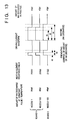
- Fig. 13 illustrates driving current waveforms applied under these conditions.
- the preheating pulse of nozzle 1 which discharges a small amount of ink has a pulse width larger than that of the preheating pulses for nozzles 100 and 150 (t1 ⁇ t2). Further, the heating pulse width t4 is larger than t3 (t4>t3).
- t5 represents the pulse width for minimum power needed to foam the ink and cause the ink droplets to be discharged from the nozzles. The following relationships hold: t1, t2 ⁇ t5 and t3, t4>t5.
- the preheating pulses are changed under conditions in which the relations t1 ⁇ t2; t1, t2 ⁇ t5 hold with respect to a change in the temperature of the board during drive.
- the amount of ink discharged from each nozzle during actual drive can be made 40 pl at all times. This makes it possible to achieve high-quality printing without unevenness and blurring.
- the pulse width is adjusted in dependence upon the resistance value of the board, whereby a constant power is applied without waste. This contributes to a longer service life for the printhead.
- Fig. 14 illustrates a change in OD value in a case where the preheating pulses are changed.
- the preheating pulses fluctuate by more than 0.5 ⁇ sec from the usual value, depending upon the particular case, owing to the correction. For example, if a drive pulse which is equivalent to a single heating pulse is on the order of 4 ⁇ sec, a pulse which is approximately 15% longer than usual is applied to a printing element discharging ink which represents a low density. This has the effect of shortening the service life of the printhead. Further, when the change in a heating pulse is large, the change in the OD value also becomes very large, as shown in Fig. 14.
- an interval (referred to as a quiescent interval) in which heating pulses are not applied is provided between preheating and main heating of the printhead, as shown in Fig. 15, thereby changing the printing density.
- a quiescent interval in which heating pulses are not applied is provided between preheating and main heating of the printhead, as shown in Fig. 15, thereby changing the printing density.
- Fig. 16 illustrates a change in the OD value in a case where the preheating pulse width and main heating pulse width are fixed and the quiescent interval is changed.
- the application of drive pulses differs from that shown in Fig. 13 with regard particularly to nozzle 1 and nozzle 200, as shown in Fig. 15.
- nozzle 1 density is somewhat lower in comparison with nozzles 100 and 150 (the amount of reduction in ink discharge is 10%). Therefore, the quiescent interval is made slightly longer (t6) in comparison with that (t7) for nozzles 100 and 150.
- nozzle 200 there is a very large difference in density in comparison with nozzles 100 and 150 (the amount of reduction in ink discharge is 20%). Therefore, while the interval time is lengthened (t6), the preheating pulse width is stretched (t2) in comparison with the heating pulse width (t1) of nozzles 1, 100 and 150 to correct the amount in ink discharge. If this arrangement is adopted, a correction of density unevenness can be achieved without applying a large change in energy to the printing elements of the printhead.
- the dots of prescribed pattern data which have been printed by a printhead, are gathered together in a prescribed plurality of areas per each nozzle (recording element) of the printhead upon taking into account the visual discriminating ability of the human eye, and information obtained from the plurality of areas can be applied as density unevenness data.
- a variation in dot-to-dot diameter which exceeds the visual discriminating ability of the human eye is no longer discerned as density unevenness.
- information capable of accurate density correction can be supplied more rapidly for each printing element.
- the width of the quiescent interval between a preheating pulse and a main heating pulse is adjusted along with the pulse widths of these pulses.
- the preheating pulses are selected on the board.
- the density correction may be performed by changing the width of the main heating pulses using a counter or the like.
- the present invention may be applied to effect a density correction if the board is such that control of the driving power of each printing element is possible.
- the same density correction can be performed even if the printhead has a construction different from that described.
- control unit on the side of the printing apparatus controls the printing operation of the printhead on the basis of correction data that has been stored in a memory within the printhead.
- control unit is provided within the printhead.
- the invention is not limited to such a printer.
- a serial printer of the type in which printing is performed by moving a printhead mounted on a carriage the invention is applicable to an arrangement in which the printing is carried out by a number of nozzles arrayed in a row in the direction in which the recording paper is conveyed.
- this invention is applicable to another type of printhead such as an ink jet printhead, thermal printhead or LED printhead.
- a printer which comprises means (e.g., an electrothermal transducer, laser beam generator, and the like) for generating heat energy as energy utilized upon execution of ink discharge, and causes a change in state of an ink by the heat energy, among the ink-jet printers.
- means e.g., an electrothermal transducer, laser beam generator, and the like
- heat energy as energy utilized upon execution of ink discharge
- the system is effective because, by applying at least one driving signal, which corresponds to printing information and gives a rapid temperature rise exceeding film boiling, to each of electrothermal transducers arranged in correspondence with a sheet or liquid channels holding a liquid (ink), heat energy is generated by the electrothermal transducer to effect film boiling on the heat acting surface of the printhead, and consequently, a bubble can be formed in the liquid (ink) in one-to-one correspondence with the driving signal.
- the driving signal is applied as a pulse signal, the growth and shrinkage of the bubble can be attained instantly and adequately to achieve discharge of the liquid (ink) with the particularly high response characteristics.
- signals disclosed in U.S. Patent Nos. 4,463,359 and 4,345,262 are suitable. Note that further excellent printing can be performed by using the conditions described in U.S. Patent No. 4,313,124 of the invention which relates to the temperature rise rate of the heat acting surface.
- the arrangement using U.S. Patent Nos. 4,558,333 and 4,459,600 which disclose the arrangement having a heat acting portion arranged in a flexed region is also included in the present invention.
- the present invention can be effectively applied to an arrangement based on Japanese Patent Laid-Open No. 59-123670 which discloses the arrangement using a slot common to a plurality of electrothermal transducers as a discharge portion of the electrothermal transducers, or Japanese Patent Laid-Open No. 59-138461 which discloses the arrangement having an opening for absorbing a pressure wave of heat energy in correspondence with a discharge portion.
- a full line type printhead having a length corresponding to the width of a maximum printing medium which can be printed by the printer
- either the arrangement which satisfies the full-line length by combining a plurality of printheads as disclosed in the above specification or the arrangement as a single printhead obtained by forming printheads integrally can be used.
- an exchangeable chip type printhead which can be electrically connected to the apparatus main unit and can receive an ink from the apparatus main unit upon being mounted on the apparatus main unit
- a cartridge type printhead in which an ink tank is integrally arranged on the printhead itself can be applicable to the present invention.
- recovery means for the printhead, preliminary auxiliary means, and the like provided as an arrangement of the printer of the present invention since the printing operation can be further stabilized.
- examples of such means include, for the printhead, capping means, cleaning means, pressurization or suction means, and preliminary heating means using electrothermal transducers, another heating element, or a combination thereof. It is also effective for stable printing to provide a preliminary discharge mode which performs discharge independently of printing.
- a printing mode of the printer not only a printing mode using only a primary color such as black or the like, but also at least one of a multicolor mode using a plurality of different colors or a full-color mode achieved by color mixing can be implemented in the printer either by using an integrated printhead or by combining a plurality of printheads.
- the ink is a liquid.
- the present invention may employ an ink which is solid at room temperature or less and softens or liquefies at room temperature, or an ink which liquefies upon application of a use printing signal, since it is a general practice to perform temperature control of the ink itself within a range from 30°C to 70°C in the ink-jet system, so that the ink viscosity can fall within a stable discharge range.
- an ink which is solid in a non-use state and liquefies upon heating may be used.
- an ink which liquefies upon application of heat energy according to a printing signal and is discharged in a liquid state, an ink which begins to solidify when it reaches a printing medium, or the like, is applicable to the present invention.
- an ink may be situated opposite electrothermal transducers while being held in a liquid or solid state in recess portions of a porous sheet or through holes, as described in Japanese Patent Laid-Open No. 54-56847 or 60-71260.
- the above-mentioned film boiling system is most effective for the above-mentioned inks.
- the ink-jet printer of the present invention may be used in the form of a copying machine combined with a reader, and the like, or a facsimile apparatus having a transmission/reception function in addition to an image output terminal of an information processing equipment such as a computer.
- the present invention can be applied to a system constituted by a plurality of devices, or to an apparatus comprising a single device. Furthermore, it goes without saying that the invention is applicable also to a case where the object of the invention is attained by supplying a program to a system or apparatus.
Applications Claiming Priority (3)
| Application Number | Priority Date | Filing Date | Title |
|---|---|---|---|
| JP265444/94 | 1994-10-28 | ||
| JP26544494 | 1994-10-28 | ||
| JP26544494A JPH08118727A (ja) | 1994-10-28 | 1994-10-28 | 記録ヘッド補正方法及びその装置及びその装置によって補正された記録ヘッド及びその記録ヘッドを用いた記録装置 |
Publications (3)
| Publication Number | Publication Date |
|---|---|
| EP0709192A2 true EP0709192A2 (de) | 1996-05-01 |
| EP0709192A3 EP0709192A3 (de) | 1996-07-31 |
| EP0709192B1 EP0709192B1 (de) | 2002-02-06 |
Family
ID=17417243
Family Applications (1)
| Application Number | Title | Priority Date | Filing Date |
|---|---|---|---|
| EP95307600A Expired - Lifetime EP0709192B1 (de) | 1994-10-28 | 1995-10-25 | Verfahren und Vorrichtung zur Korrektur eines Druckkopfes, mittels dieser Vorrichtung korrigierter Druckkopf und diesen Druckkopf verwendende Druckvorrichtung |
Country Status (4)
| Country | Link |
|---|---|
| US (1) | US6042213A (de) |
| EP (1) | EP0709192B1 (de) |
| JP (1) | JPH08118727A (de) |
| DE (1) | DE69525303T2 (de) |
Cited By (12)
| Publication number | Priority date | Publication date | Assignee | Title |
|---|---|---|---|---|
| EP0816085A2 (de) * | 1996-06-28 | 1998-01-07 | Canon Kabushiki Kaisha | Verfahren zur Regelung der Menge von aus einer Mehrzahl von Flüssigkeitsausstossdüseeinheiten ausgestossener Flüssigkeit, Tintenstrahlsteuerverfahren unter Anwendung dieses Regelverfahrens und Tintenstrahlapparat |
| EP0832745A2 (de) * | 1996-09-30 | 1998-04-01 | Canon Kabushiki Kaisha | Tintenstrahldruckverfahren und Tintenstrahldruckvorrichtung, Farbfilter, Anzeigevorrichtung, Apparat mit einer Anzeigevorrichtung, Vorrichtung und Verfahren zum Justieren einer Tintenstrahlkopfeinheit und Tintenstrahlkopfeinheit |
| GB2325438A (en) * | 1997-05-21 | 1998-11-25 | Markem Tech Ltd | An ink jet printing method involving analysis of individual printing elements of a printhead and production of a modified printhead control signal |
| DE19755873A1 (de) * | 1997-12-04 | 1999-06-10 | Francotyp Postalia Gmbh | Anordnung zum Toleranzausgleich bei einem Tintendruckkopf |
| DE19755874C1 (de) * | 1997-12-04 | 1999-07-15 | Francotyp Postalia Gmbh | Verfahren zum Toleranzausgleich bei einem aus mehreren Modulen nach dem Non-Interlaced-Prinzip zusammengesetzten Tintendruckkopf |
| US6164746A (en) * | 1993-09-24 | 2000-12-26 | Canon Kabushiki Kaisha | Ink-jet printer method and apparatus, color filter, display device, apparatus having display device, ink-jet head unit adjusting device and method, and ink-jet head unit |
| US6582048B1 (en) | 1996-09-30 | 2003-06-24 | Canon Kabushiki Kaisha | Ink-jet print method and apparatus, color filter, display device, apparatus having display device, ink-jet head unit adjusting device and method, and ink-jet head unit |
| WO2004007204A2 (en) * | 2002-07-11 | 2004-01-22 | Willett International Limited | Solenoid valve for a drop on demand ink jet printer |
| EP1623830A1 (de) * | 2004-08-05 | 2006-02-08 | Brother Kogyo Kabushiki Kaisha | Zeilenkopftintenstrahldrucker |
| AT501317A1 (de) * | 2005-02-08 | 2006-08-15 | Durst Phototech Digital Tech | Tintenstrahldruckvorrichtung und verfahren zum justieren von druckköpfen |
| SG136792A1 (en) * | 1997-07-15 | 2007-11-29 | Silverbrook Res Pty Ltd | Artcard for the administration of the operation of a camera device |
| SG144696A1 (en) * | 1999-04-23 | 2008-08-28 | Silverbrook Res Pty Ltd | A duplex network color printer |
Families Citing this family (34)
| Publication number | Priority date | Publication date | Assignee | Title |
|---|---|---|---|---|
| EP0822072B1 (de) * | 1996-07-31 | 2003-09-24 | Canon Kabushiki Kaisha | Aufzeichnungskopf und Aufzeichnungsverfahren |
| US6367903B1 (en) * | 1997-02-06 | 2002-04-09 | Hewlett-Packard Company | Alignment of ink dots in an inkjet printer |
| US6786420B1 (en) | 1997-07-15 | 2004-09-07 | Silverbrook Research Pty. Ltd. | Data distribution mechanism in the form of ink dots on cards |
| US6618117B2 (en) | 1997-07-12 | 2003-09-09 | Silverbrook Research Pty Ltd | Image sensing apparatus including a microcontroller |
| US6803989B2 (en) * | 1997-07-15 | 2004-10-12 | Silverbrook Research Pty Ltd | Image printing apparatus including a microcontroller |
| US6948794B2 (en) | 1997-07-15 | 2005-09-27 | Silverbrook Reserach Pty Ltd | Printhead re-capping assembly for a print and demand digital camera system |
| US6624848B1 (en) | 1997-07-15 | 2003-09-23 | Silverbrook Research Pty Ltd | Cascading image modification using multiple digital cameras incorporating image processing |
| US7286169B2 (en) * | 1998-07-10 | 2007-10-23 | Silverbrook Research Pty Ltd | Cascading image modification using multiple digital cameras incorporating image processing |
| US6665008B1 (en) | 1997-07-15 | 2003-12-16 | Silverbrook Research Pty Ltd | Artcard for the control of the operation of a camera device |
| AUPO802797A0 (en) | 1997-07-15 | 1997-08-07 | Silverbrook Research Pty Ltd | Image processing method and apparatus (ART54) |
| US6304291B1 (en) * | 1997-07-15 | 2001-10-16 | Silverbrook Research Pty Ltd | Artcard for the administration of the operation of a camera device |
| US6985207B2 (en) | 1997-07-15 | 2006-01-10 | Silverbrook Research Pty Ltd | Photographic prints having magnetically recordable media |
| US6879341B1 (en) | 1997-07-15 | 2005-04-12 | Silverbrook Research Pty Ltd | Digital camera system containing a VLIW vector processor |
| US7724282B2 (en) | 1997-07-15 | 2010-05-25 | Silverbrook Research Pty Ltd | Method of processing digital image to correct for flash effects |
| US7714889B2 (en) * | 1997-07-15 | 2010-05-11 | Silverbrook Research Pty Ltd | Digital camera using exposure information for image processing |
| AUPO850597A0 (en) | 1997-08-11 | 1997-09-04 | Silverbrook Research Pty Ltd | Image processing method and apparatus (art01a) |
| US6690419B1 (en) | 1997-07-15 | 2004-02-10 | Silverbrook Research Pty Ltd | Utilising eye detection methods for image processing in a digital image camera |
| US7110024B1 (en) | 1997-07-15 | 2006-09-19 | Silverbrook Research Pty Ltd | Digital camera system having motion deblurring means |
| AU7455498A (en) | 1998-05-29 | 1999-12-20 | Citizen Watch Co. Ltd. | Method of subjecting ink jet printer to preuse treatment |
| AUPP702098A0 (en) | 1998-11-09 | 1998-12-03 | Silverbrook Research Pty Ltd | Image creation method and apparatus (ART73) |
| AUPQ056099A0 (en) | 1999-05-25 | 1999-06-17 | Silverbrook Research Pty Ltd | A method and apparatus (pprint01) |
| JP3507366B2 (ja) * | 1999-07-19 | 2004-03-15 | キヤノン株式会社 | 記録装置および記録装置の画像データ処理方法 |
| US6655771B2 (en) * | 2000-06-27 | 2003-12-02 | Fuji Photo Film Co., Ltd. | Head position detecting method, recording head, image recording apparatus and storage medium |
| US7227673B2 (en) | 2001-01-23 | 2007-06-05 | Hewlett-Packard Development Company, L.P. | Color measurement with distributed sensors in a color hard copy apparatus |
| JP2004066467A (ja) * | 2002-08-01 | 2004-03-04 | Canon Inc | 記録装置とその制御方法及び記録ヘッド、記録ヘッド用素子基体、液体吐出装置、液体吐出ヘッド並びに液体吐出ヘッド用素子基体 |
| JP2004160970A (ja) | 2002-09-19 | 2004-06-10 | Ricoh Co Ltd | 画像処理方法、記録装置、インクジェット記録装置、プリンタドライバ、画像処理装置、画像形成システム及び画像形成方法 |
| JP4596757B2 (ja) * | 2003-08-05 | 2010-12-15 | キヤノン株式会社 | 記録ヘッド試験装置 |
| US7118189B2 (en) * | 2004-05-28 | 2006-10-10 | Videojet Technologies Inc. | Autopurge printing system |
| JP4517766B2 (ja) * | 2004-08-05 | 2010-08-04 | ブラザー工業株式会社 | ライン式インクジェットプリンタにおけるインク吐出量補正方法 |
| US20060055720A1 (en) * | 2004-09-10 | 2006-03-16 | Olson Stephen T | Method for intra-swath banding compensation |
| JP4552581B2 (ja) * | 2004-09-29 | 2010-09-29 | セイコーエプソン株式会社 | 印刷装置、及び単位信号調整方法 |
| JP5226723B2 (ja) * | 2010-03-29 | 2013-07-03 | 大日本スクリーン製造株式会社 | 印刷装置、および、濃度補正方法 |
| US8511776B2 (en) | 2010-07-12 | 2013-08-20 | Hewlett-Packard Development Company, L.P. | Maintaining optical density of images produced by a printing device |
| JP5906630B2 (ja) * | 2011-09-21 | 2016-04-20 | セイコーエプソン株式会社 | 画像処理装置、画像処理方法、及び液体吐出装置 |
Citations (16)
| Publication number | Priority date | Publication date | Assignee | Title |
|---|---|---|---|---|
| JPS5456847A (en) | 1977-10-14 | 1979-05-08 | Canon Inc | Medium for thermo transfer recording |
| JPS55132253A (en) | 1979-04-02 | 1980-10-14 | Canon Inc | Recorder |
| US4313124A (en) | 1979-05-18 | 1982-01-26 | Canon Kabushiki Kaisha | Liquid jet recording process and liquid jet recording head |
| US4345262A (en) | 1979-02-19 | 1982-08-17 | Canon Kabushiki Kaisha | Ink jet recording method |
| US4459600A (en) | 1978-10-31 | 1984-07-10 | Canon Kabushiki Kaisha | Liquid jet recording device |
| JPS59123670A (ja) | 1982-12-28 | 1984-07-17 | Canon Inc | インクジエツトヘツド |
| US4463359A (en) | 1979-04-02 | 1984-07-31 | Canon Kabushiki Kaisha | Droplet generating method and apparatus thereof |
| JPS59138461A (ja) | 1983-01-28 | 1984-08-08 | Canon Inc | 液体噴射記録装置 |
| JPS6071260A (ja) | 1983-09-28 | 1985-04-23 | Erumu:Kk | 記録装置 |
| US4558333A (en) | 1981-07-09 | 1985-12-10 | Canon Kabushiki Kaisha | Liquid jet recording head |
| US4723129A (en) | 1977-10-03 | 1988-02-02 | Canon Kabushiki Kaisha | Bubble jet recording method and apparatus in which a heating element generates bubbles in a liquid flow path to project droplets |
| JPH022009A (ja) | 1987-12-23 | 1990-01-08 | Xerox Corp | 大型アレー・サーマル・インクジェット印字ヘッド |
| US5016023A (en) | 1989-10-06 | 1991-05-14 | Hewlett-Packard Company | Large expandable array thermal ink jet pen and method of manufacturing same |
| JPH04229278A (ja) | 1990-05-01 | 1992-08-18 | Xerox Corp | ページ幅インクジェット印字ヘッドを製造する方法 |
| JPH04232749A (ja) | 1990-06-22 | 1992-08-21 | Xerox Corp | ジグザグ配置インクジェット印字ヘッド |
| JPH0524192A (ja) | 1990-06-26 | 1993-02-02 | Xerox Corp | ページ幅ジグザグ配置アレー型印字ヘツド |
Family Cites Families (14)
| Publication number | Priority date | Publication date | Assignee | Title |
|---|---|---|---|---|
| US4596995A (en) * | 1983-06-24 | 1986-06-24 | Canon Kabushiki Kaisha | Dot printer having means for correcting intensity variations |
| EP0317268B1 (de) * | 1987-11-16 | 1997-07-23 | Canon Kabushiki Kaisha | Bildaufzeichnungsgerät |
| DE69033001T2 (de) * | 1989-10-05 | 1999-09-09 | Canon Kk | Bilderzeugungsgerät |
| US5202773A (en) * | 1989-12-22 | 1993-04-13 | Fuji Xerox Co., Ltd. | Multiple value image input device with chromatic gradation correction |
| JP2863241B2 (ja) * | 1990-02-02 | 1999-03-03 | キヤノン株式会社 | 記録ヘッドおよび記録ヘッド駆動方法 |
| DE69115065T2 (de) * | 1990-02-02 | 1996-05-15 | Canon Kk | Verfahren und Gerät zur Aufzeichnung. |
| EP0452157B1 (de) * | 1990-04-13 | 1995-10-18 | Canon Kabushiki Kaisha | Bildaufzeichnungsapparat |
| JP2950950B2 (ja) * | 1990-08-31 | 1999-09-20 | キヤノン株式会社 | 画像記録装置 |
| GB2272115B (en) * | 1992-11-03 | 1996-09-04 | Bowthorpe Plc | Cable splice closure |
| US5502468A (en) * | 1992-12-28 | 1996-03-26 | Tektronix, Inc. | Ink jet print head drive with normalization |
| US5508826A (en) * | 1993-04-27 | 1996-04-16 | Lloyd; William J. | Method and apparatus for calibrated digital printing using a four by four transformation matrix |
| US5510896A (en) * | 1993-06-18 | 1996-04-23 | Xerox Corporation | Automatic copy quality correction and calibration |
| US6116714A (en) * | 1994-03-04 | 2000-09-12 | Canon Kabushiki Kaisha | Printing head, printing method and apparatus using same, and apparatus and method for correcting said printing head |
| JP3083441B2 (ja) * | 1994-03-04 | 2000-09-04 | キヤノン株式会社 | プリントヘッド及びその製造装置及び製造方法及びプリント装置 |
-
1994
- 1994-10-28 JP JP26544494A patent/JPH08118727A/ja active Pending
-
1995
- 1995-10-19 US US08/545,463 patent/US6042213A/en not_active Expired - Fee Related
- 1995-10-25 DE DE69525303T patent/DE69525303T2/de not_active Expired - Lifetime
- 1995-10-25 EP EP95307600A patent/EP0709192B1/de not_active Expired - Lifetime
Patent Citations (17)
| Publication number | Priority date | Publication date | Assignee | Title |
|---|---|---|---|---|
| US4740796A (en) | 1977-10-03 | 1988-04-26 | Canon Kabushiki Kaisha | Bubble jet recording method and apparatus in which a heating element generates bubbles in multiple liquid flow paths to project droplets |
| US4723129A (en) | 1977-10-03 | 1988-02-02 | Canon Kabushiki Kaisha | Bubble jet recording method and apparatus in which a heating element generates bubbles in a liquid flow path to project droplets |
| JPS5456847A (en) | 1977-10-14 | 1979-05-08 | Canon Inc | Medium for thermo transfer recording |
| US4459600A (en) | 1978-10-31 | 1984-07-10 | Canon Kabushiki Kaisha | Liquid jet recording device |
| US4345262A (en) | 1979-02-19 | 1982-08-17 | Canon Kabushiki Kaisha | Ink jet recording method |
| JPS55132253A (en) | 1979-04-02 | 1980-10-14 | Canon Inc | Recorder |
| US4463359A (en) | 1979-04-02 | 1984-07-31 | Canon Kabushiki Kaisha | Droplet generating method and apparatus thereof |
| US4313124A (en) | 1979-05-18 | 1982-01-26 | Canon Kabushiki Kaisha | Liquid jet recording process and liquid jet recording head |
| US4558333A (en) | 1981-07-09 | 1985-12-10 | Canon Kabushiki Kaisha | Liquid jet recording head |
| JPS59123670A (ja) | 1982-12-28 | 1984-07-17 | Canon Inc | インクジエツトヘツド |
| JPS59138461A (ja) | 1983-01-28 | 1984-08-08 | Canon Inc | 液体噴射記録装置 |
| JPS6071260A (ja) | 1983-09-28 | 1985-04-23 | Erumu:Kk | 記録装置 |
| JPH022009A (ja) | 1987-12-23 | 1990-01-08 | Xerox Corp | 大型アレー・サーマル・インクジェット印字ヘッド |
| US5016023A (en) | 1989-10-06 | 1991-05-14 | Hewlett-Packard Company | Large expandable array thermal ink jet pen and method of manufacturing same |
| JPH04229278A (ja) | 1990-05-01 | 1992-08-18 | Xerox Corp | ページ幅インクジェット印字ヘッドを製造する方法 |
| JPH04232749A (ja) | 1990-06-22 | 1992-08-21 | Xerox Corp | ジグザグ配置インクジェット印字ヘッド |
| JPH0524192A (ja) | 1990-06-26 | 1993-02-02 | Xerox Corp | ページ幅ジグザグ配置アレー型印字ヘツド |
Cited By (26)
| Publication number | Priority date | Publication date | Assignee | Title |
|---|---|---|---|---|
| US6164746A (en) * | 1993-09-24 | 2000-12-26 | Canon Kabushiki Kaisha | Ink-jet printer method and apparatus, color filter, display device, apparatus having display device, ink-jet head unit adjusting device and method, and ink-jet head unit |
| EP0816085A3 (de) * | 1996-06-28 | 1998-12-09 | Canon Kabushiki Kaisha | Verfahren zur Regelung der Menge von aus einer Mehrzahl von Flüssigkeitsausstossdüseeinheiten ausgestossener Flüssigkeit, Tintenstrahlsteuerverfahren unter Anwendung dieses Regelverfahrens und Tintenstrahlapparat |
| EP0816085A2 (de) * | 1996-06-28 | 1998-01-07 | Canon Kabushiki Kaisha | Verfahren zur Regelung der Menge von aus einer Mehrzahl von Flüssigkeitsausstossdüseeinheiten ausgestossener Flüssigkeit, Tintenstrahlsteuerverfahren unter Anwendung dieses Regelverfahrens und Tintenstrahlapparat |
| EP0832745A2 (de) * | 1996-09-30 | 1998-04-01 | Canon Kabushiki Kaisha | Tintenstrahldruckverfahren und Tintenstrahldruckvorrichtung, Farbfilter, Anzeigevorrichtung, Apparat mit einer Anzeigevorrichtung, Vorrichtung und Verfahren zum Justieren einer Tintenstrahlkopfeinheit und Tintenstrahlkopfeinheit |
| EP0832745A3 (de) * | 1996-09-30 | 1999-06-23 | Canon Kabushiki Kaisha | Tintenstrahldruckverfahren und Tintenstrahldruckvorrichtung, Farbfilter, Anzeigevorrichtung, Apparat mit einer Anzeigevorrichtung, Vorrichtung und Verfahren zum Justieren einer Tintenstrahlkopfeinheit und Tintenstrahlkopfeinheit |
| US6582048B1 (en) | 1996-09-30 | 2003-06-24 | Canon Kabushiki Kaisha | Ink-jet print method and apparatus, color filter, display device, apparatus having display device, ink-jet head unit adjusting device and method, and ink-jet head unit |
| US6290316B1 (en) | 1997-05-21 | 2001-09-18 | Markem Technologies Limited | Method of printing |
| GB2325438A (en) * | 1997-05-21 | 1998-11-25 | Markem Tech Ltd | An ink jet printing method involving analysis of individual printing elements of a printhead and production of a modified printhead control signal |
| GB2325438B (en) * | 1997-05-21 | 2001-07-11 | Markem Tech Ltd | Method of printing |
| SG136792A1 (en) * | 1997-07-15 | 2007-11-29 | Silverbrook Res Pty Ltd | Artcard for the administration of the operation of a camera device |
| DE19755874C1 (de) * | 1997-12-04 | 1999-07-15 | Francotyp Postalia Gmbh | Verfahren zum Toleranzausgleich bei einem aus mehreren Modulen nach dem Non-Interlaced-Prinzip zusammengesetzten Tintendruckkopf |
| DE19755873A1 (de) * | 1997-12-04 | 1999-06-10 | Francotyp Postalia Gmbh | Anordnung zum Toleranzausgleich bei einem Tintendruckkopf |
| DE19755873C2 (de) * | 1997-12-04 | 1999-10-14 | Francotyp Postalia Gmbh | Anordnung zum Toleranzausgleich bei einem Tintendruckkopf |
| US6457800B1 (en) | 1997-12-04 | 2002-10-01 | Francotyp Postalia Ag & Co. K.G. | Method for tolerance compensation in an ink jet print head |
| US8059309B2 (en) | 1999-04-23 | 2011-11-15 | Silverbrook Research Pty Ltd | Duplex printer with internal hard drive |
| SG144696A1 (en) * | 1999-04-23 | 2008-08-28 | Silverbrook Res Pty Ltd | A duplex network color printer |
| WO2004007204A3 (en) * | 2002-07-11 | 2004-03-25 | Willett Int Ltd | Solenoid valve for a drop on demand ink jet printer |
| WO2004007204A2 (en) * | 2002-07-11 | 2004-01-22 | Willett International Limited | Solenoid valve for a drop on demand ink jet printer |
| EP1623829A1 (de) * | 2004-08-05 | 2006-02-08 | Brother Kogyo Kabushiki Kaisha | Zeilenkopftintenstrahldrucker |
| EP1623831A1 (de) * | 2004-08-05 | 2006-02-08 | Brother Kogyo Kabushiki Kaisha | Verfahren zum Korrigieren der Menge ausgestossener Tinte in einem Zeilenkopftintenstrahldrucker |
| EP1623830A1 (de) * | 2004-08-05 | 2006-02-08 | Brother Kogyo Kabushiki Kaisha | Zeilenkopftintenstrahldrucker |
| US7445304B2 (en) | 2004-08-05 | 2008-11-04 | Brother Kogyo Kabushiki Kaisha | Line head inkjet printer |
| US7488049B2 (en) | 2004-08-05 | 2009-02-10 | Brother Kogyo Kabushiki Kaisha | Line head inkjet printer |
| US7500729B2 (en) | 2004-08-05 | 2009-03-10 | Brother Kogyo Kabushiki Kaisha | Method for correcting an amount of ejected ink in line head inkjet printer |
| AT501317A1 (de) * | 2005-02-08 | 2006-08-15 | Durst Phototech Digital Tech | Tintenstrahldruckvorrichtung und verfahren zum justieren von druckköpfen |
| AT501317B1 (de) * | 2005-02-08 | 2007-08-15 | Durst Phototech Digital Tech | Tintenstrahldruckvorrichtung und verfahren zum justieren von druckköpfen |
Also Published As
| Publication number | Publication date |
|---|---|
| EP0709192B1 (de) | 2002-02-06 |
| US6042213A (en) | 2000-03-28 |
| DE69525303D1 (de) | 2002-03-21 |
| DE69525303T2 (de) | 2002-08-14 |
| EP0709192A3 (de) | 1996-07-31 |
| JPH08118727A (ja) | 1996-05-14 |
Similar Documents
| Publication | Publication Date | Title |
|---|---|---|
| US6042213A (en) | Method and apparatus for correcting printhead, printhead corrected by this apparatus, and printing apparatus using this printhead | |
| US6094280A (en) | Method and apparatus for correcting print density by printhead, printhead corrected by this apparatus, and printing apparatus using this printhead | |
| EP0709213B1 (de) | Verfahren und Vorrichtung für Korrektionskopf und Drucker mit diesem Kopf | |
| EP0729115B1 (de) | Verfahren und Vorrichtung zur Druckkopfkalibrierung, Druckkopf und Drucker | |
| US6616257B2 (en) | Printing head, printing method and apparatus using same, and apparatus and method for correcting said printing head | |
| EP0997287A2 (de) | Temperatursteuerung für Tintenstrahlaufzeichnungskopf unter Verwendung von Wärmeenergie | |
| US6377358B1 (en) | Method for correcting a recording head, correction apparatus therefor, recording head corrected by use of such apparatus, and recording apparatus using such recording head | |
| JP3083441B2 (ja) | プリントヘッド及びその製造装置及び製造方法及びプリント装置 | |
| US6325482B1 (en) | Method and apparatus for correcting printhead, printhead corrected by this apparatus, and printing apparatus using this printhead | |
| EP1254773A1 (de) | Druckvorrichtung und Drucksteuerungsverfahren | |
| US8579400B2 (en) | Information processing apparatus and information processing method | |
| JPH11240149A (ja) | 記録ヘッド補正方法、その補正装置、その装置によって補正された記録ヘッド及びその記録ヘッドを用いた記録装置 | |
| US7452050B2 (en) | Head substrate, printhead, head cartridge, and printing apparatus using the printhead or head cartridge | |
| US20200139706A1 (en) | Element substrate, printhead and printing apparatus | |
| JP3441915B2 (ja) | 記録装置 | |
| JP2004090246A (ja) | 記録ヘッド用基板、インクジェット記録ヘッド、記録装置およびランクヒーター測定方法 | |
| JPH06297718A (ja) | インクジェット記録装置 | |
| JP2001301143A (ja) | インクジェット記録装置およびそのヘッド駆動方法 |
Legal Events
| Date | Code | Title | Description |
|---|---|---|---|
| PUAI | Public reference made under article 153(3) epc to a published international application that has entered the european phase |
Free format text: ORIGINAL CODE: 0009012 |
|
| AK | Designated contracting states |
Kind code of ref document: A2 Designated state(s): DE FR GB IT |
|
| PUAL | Search report despatched |
Free format text: ORIGINAL CODE: 0009013 |
|
| AK | Designated contracting states |
Kind code of ref document: A3 Designated state(s): DE FR GB IT |
|
| 17P | Request for examination filed |
Effective date: 19961211 |
|
| 17Q | First examination report despatched |
Effective date: 19980128 |
|
| GRAG | Despatch of communication of intention to grant |
Free format text: ORIGINAL CODE: EPIDOS AGRA |
|
| GRAG | Despatch of communication of intention to grant |
Free format text: ORIGINAL CODE: EPIDOS AGRA |
|
| GRAH | Despatch of communication of intention to grant a patent |
Free format text: ORIGINAL CODE: EPIDOS IGRA |
|
| GRAH | Despatch of communication of intention to grant a patent |
Free format text: ORIGINAL CODE: EPIDOS IGRA |
|
| GRAA | (expected) grant |
Free format text: ORIGINAL CODE: 0009210 |
|
| REG | Reference to a national code |
Ref country code: GB Ref legal event code: IF02 |
|
| AK | Designated contracting states |
Kind code of ref document: B1 Designated state(s): DE FR GB IT |
|
| PG25 | Lapsed in a contracting state [announced via postgrant information from national office to epo] |
Ref country code: IT Free format text: LAPSE BECAUSE OF FAILURE TO SUBMIT A TRANSLATION OF THE DESCRIPTION OR TO PAY THE FEE WITHIN THE PRESCRIBED TIME-LIMIT;WARNING: LAPSES OF ITALIAN PATENTS WITH EFFECTIVE DATE BEFORE 2007 MAY HAVE OCCURRED AT ANY TIME BEFORE 2007. THE CORRECT EFFECTIVE DATE MAY BE DIFFERENT FROM THE ONE RECORDED. Effective date: 20020206 Ref country code: FR Free format text: LAPSE BECAUSE OF FAILURE TO SUBMIT A TRANSLATION OF THE DESCRIPTION OR TO PAY THE FEE WITHIN THE PRESCRIBED TIME-LIMIT Effective date: 20020206 |
|
| REF | Corresponds to: |
Ref document number: 69525303 Country of ref document: DE Date of ref document: 20020321 |
|
| EN | Fr: translation not filed | ||
| PLBE | No opposition filed within time limit |
Free format text: ORIGINAL CODE: 0009261 |
|
| STAA | Information on the status of an ep patent application or granted ep patent |
Free format text: STATUS: NO OPPOSITION FILED WITHIN TIME LIMIT |
|
| 26N | No opposition filed |
Effective date: 20021107 |
|
| PGFP | Annual fee paid to national office [announced via postgrant information from national office to epo] |
Ref country code: DE Payment date: 20101031 Year of fee payment: 16 |
|
| PGFP | Annual fee paid to national office [announced via postgrant information from national office to epo] |
Ref country code: GB Payment date: 20101019 Year of fee payment: 16 |
|
| GBPC | Gb: european patent ceased through non-payment of renewal fee |
Effective date: 20111025 |
|
| PG25 | Lapsed in a contracting state [announced via postgrant information from national office to epo] |
Ref country code: DE Free format text: LAPSE BECAUSE OF NON-PAYMENT OF DUE FEES Effective date: 20120501 |
|
| REG | Reference to a national code |
Ref country code: DE Ref legal event code: R119 Ref document number: 69525303 Country of ref document: DE Effective date: 20120501 |
|
| PG25 | Lapsed in a contracting state [announced via postgrant information from national office to epo] |
Ref country code: GB Free format text: LAPSE BECAUSE OF NON-PAYMENT OF DUE FEES Effective date: 20111025 |