EP0708441A2 - Dispositif de reproduction de disque - Google Patents
Dispositif de reproduction de disque Download PDFInfo
- Publication number
- EP0708441A2 EP0708441A2 EP95113170A EP95113170A EP0708441A2 EP 0708441 A2 EP0708441 A2 EP 0708441A2 EP 95113170 A EP95113170 A EP 95113170A EP 95113170 A EP95113170 A EP 95113170A EP 0708441 A2 EP0708441 A2 EP 0708441A2
- Authority
- EP
- European Patent Office
- Prior art keywords
- disk
- disks
- drive belt
- playback
- stocker
- Prior art date
- Legal status (The legal status is an assumption and is not a legal conclusion. Google has not performed a legal analysis and makes no representation as to the accuracy of the status listed.)
- Granted
Links
Images


Classifications
-
- G—PHYSICS
- G11—INFORMATION STORAGE
- G11B—INFORMATION STORAGE BASED ON RELATIVE MOVEMENT BETWEEN RECORD CARRIER AND TRANSDUCER
- G11B17/00—Guiding record carriers not specifically of filamentary or web form, or of supports therefor
- G11B17/08—Guiding record carriers not specifically of filamentary or web form, or of supports therefor from consecutive-access magazine of disc records
- G11B17/10—Guiding record carriers not specifically of filamentary or web form, or of supports therefor from consecutive-access magazine of disc records with horizontal transfer to the turntable from a stack arranged with a vertical axis
-
- G—PHYSICS
- G11—INFORMATION STORAGE
- G11B—INFORMATION STORAGE BASED ON RELATIVE MOVEMENT BETWEEN RECORD CARRIER AND TRANSDUCER
- G11B17/00—Guiding record carriers not specifically of filamentary or web form, or of supports therefor
- G11B17/22—Guiding record carriers not specifically of filamentary or web form, or of supports therefor from random access magazine of disc records
- G11B17/221—Guiding record carriers not specifically of filamentary or web form, or of supports therefor from random access magazine of disc records with movable magazine
Definitions
- the present invention relates to a disk playback device that uses at least one endless drive belt to transport a disk between a storage position, a disk playback position, and an eject position. More specifically the present invention relates to such disk players that store disks in a storage device with a minimal vertical clearance requirement.
- Disk playback devices that transport disks between a storage position, a disk playback position, and an eject position are known.
- Japanese Examined Patent Publication No. 7-7560 and corresponding U.S. Patent 5,123,001 show a changer-type disk playback device with a stocker capable of storing multiple disks.
- a transfer mechanism of the disk playback device transfers disks between an eject position, a playback position, and the stocker.
- the transfer mechanism has a tray that supports the carriage. The tray transports the disk by moving the carriage, with the disk supported thereon, between the eject position and the playback position.
- disk playback devices that use at least one drive belt for transporting disks are known.
- Devices described in Japanese Utility Model Laid-open Publication No. 60-106250 and Japanese Utility Model Laid-open Publication No. 61-24851 each use a pair of endless drive belts for transporting disks between eject playback, and stocker positions.
- Japanese Laid-open Patent No. 62-47893 also discloses an invention that uses a single endless drive belt to transport disks between a stocker and a playback position.
- a belt-driven transport mechanism of a disk player, transfers disks between two positions; one inside a storage mechanism and one outside the storage mechanism.
- the transport mechanism does not have the ability to eject the disk.
- none of the above prior art devices shows a mechanism for transporting disks between eject, playback, and storage positions.
- a disk playback device has at least one endless drive belt stretched along the direction of disk transport, between a store position, a playback position and an eject position.
- the endless drive belt is transferred in a direction perpendicular to the direction of disk transport along a plane parallel to said disk, allowing the drive belt to move away from said disk rim without requiring a large space parallel to the disk.
- a changer-type disk playback device comprising a chassis, a stocker on said chassis for holding a plurality of disks, disk playback means for playing back one of said plurality of disks, at least one endless drive belt rotatably supported by said chassis, said at least one endless drive belt being supported at least two points of said chassis to form at least one taut portion running between said at least two points, said taut portion running along a direction of disk transfer, between a disk storage position within said stocker, a playback position at said disk playback means, and an eject position, said taut portion engaging with a rim of said one of said plurality of disks, whereby said one of said plurality of disks is moved between said storage, playback, and eject positions when said at least one endless drive belt is rotated, and drive means for rotating said at least one endless drive belt.
- a disk transfer device comprising means for playing back disks, means for transporting a disk between a playback position at said means for playing back disks and an eject position, said means for transporting including a drive belt held taut alongside a path of transport of said disk, said playback and eject positions lying along said path of transport, means for engaging a rim of said disk with said drive belt, means for rotating said drive belt, whereby said disk is moved along said path of transport when said rim is engaged with said drive belt and said drive belt is rotated, drive means for rotating said drive belt, and transferring means for transferring said drive belt in a direction perpendicular to said path of transport, whereby said drive belt is moved away from said rim.
- a changer-type disk playback device comprising a chassis, a stocker movably mounted on said chassis so that said stocker can move vertically, said stocker having means for storing a plurality of disks, means for playing back a selected on of said plurality of disks, an endless drive belt, means for engaging said endless drive belt with a rim of said disk, means for supporting said endless drive belt at two points of said chassis so that a free-spanning portion runs between said two points, said free-spanning portion being parallel to a path of travel along which said disk is moved, said path of travel connecting a disk storage position within said stocker, a playback position, at said disk playback means, and an eject position, drive means for rotating said endless drive belt, whereby said disk engaged with said endless drive belt is caused to move along said path of travel, means opposite said drive belt for supporting said rim at first point of said rim opposite a second point of said rim at which said drive belt contacts said rim to engage said rim, and
- a changer-type disk playback device comprising a vertically movably mounted stocker for storing a plurality of disks, a pair of endless drive belts, stretched parallel to each other, each of said pair of endless drive belts having an inner and an outer surface, transferring means for moving said pair of endless drive belts toward and away from each other, such that a portion of said outer surface of each one of said pair of endless drive belts engages one of two opposing positions on a rim of a disk, driving means for rotating at least one of said pair of endless drive belts, such that said disk is transported between a disk storage position, a disk playback position and an eject position, means for playing back said selected disk while said selected disk is in said playback position, and said transferring means being effective for keeping said endless drive belts parallel when said endless drive belts are moved toward and away from each other.
- a changer-type disk playback device comprising a longitudinal drive member having a portion with a surface, means for moving said surface along a direction of travel of a disk, a support member, opposite said surface, for urging an edge of said disk against said surface, whereby said disk is moved in said direction of travel when said surface is moved, said disk moving from a storage position, to a playback position upon a moving of said surface, said disk moving from said playback position to an eject position upon a further moving of said surface, said drive member and said support member being separated by a first distance when said support member urges said edge of said disk against said surface, and means for separating said drive member and said support member by a distance greater than said first distance, whereby said disk is no longer urged against said surface.
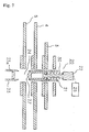
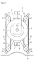
- Fig. 1 is a plan of the disk playback device.
- Fig. 2 is a front-view of the disk playback device.
- Fig. 3 is a cross-section view along the A-A line in Fig. 1.
- Fig. 4 is a plan view of the disk playback device shown in Fig. 1 where stocker 10, drive belts 31 and 32, drive pulleys 33 and 35, and driven pulleys 34 and 36 are omitted.
- Fig. 5 is a schematic front-view showing a disk position restricting means.
- Fig. 6 is a cross-section view of the disk position restricting means of Fig. 5.
- Fig. 7 is a cross-section view showing disk position restricting means of Fig. 5 when a gap is opened.
- Fig. 8 is a block diagram of the circuit controlling the motors which drive the drive belts.
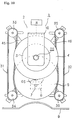
- Fig. 9 is a plan view of the disk playback device showing the pair of drive belts holding a disk.
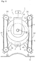
- Fig. 10 is a plan view of the disk playback device showing a disk in an initial playback position.
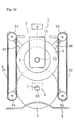
- Fig. 11 is a plan view of the disk playback device a disk in a final playback position.
- Fig. 12(a) is a view showing a disk in the disk playback device before being moved into the stocker.
- Fig. 12(b) is a view showing a disk and disk position restricting means as the disk is being transported into the stocker.
- Fig. 12(c) is a view showing a disk and disk position restricting means after it has been transported into the stocker
- Fig. 13 is a schematic cross-section of the disk position restricting means with the regulating shaft is pressed against the disk.
- Fig. 14 is a plan view of the disk playback device showing the pair of drive belts holding an 8 cm. disk.
- Fig. 15 is a plan view of the disk playback device showing an 8 cm. disk in the initial playback position.
- Fig. 16 is a plan view of the disk playback device showing the disk in the eject position.
- Fig. 17 is a plan view of the device in the loading standby state.
- a changer-type disk playback device 1 holds three disks.
- Disk playback device 1 has a chassis 2 and a front panel 9.
- Front panel 9 has a slit-shaped opening (not shown in the drawings) for receiving and ejecting one of the disks.
- disk playback device 1 also includes a stocker 10 in which an 8 cm. disk 3, having an outer diameter of 8cm., and first and second 12 cm. disks 4 and 5, having outer diameters of 12 cm., are stored. Eight cm. disk 3 and first and second 12 cm. disks 4 and 5 are concentrically aligned within stocker 10.
- a stocker transferring mechanism 8 is positioned to move stocker 10 vertically (ie, perpendicular to the plane of Fig. 1) relative to chassis 2.
- mounting plates 11, 12, and 13, on which 8 cm. disk 3 and first and second 12 cm. disks 4 and 5 are mounted attach to a vertical wall 19 at the rear end of stocker 10.
- Upper surfaces 14, 15, and 16 of mounting plates 11, 12, and 13 support 8 cm. disk 3 and first and second 12 cm. disks 4 and 5, respectively.
- An endless drive belt 31 is supported by a drive pulley 33 and a driven pulley 34.
- Another endless drive belt 32 is supported by a drive pulley 35 and a driven pulley 36.
- Endless drive belts 31 and 32 are held taut by respective pulleys creating straight spanning portions of drive belts 31 and 32 between them.
- Endless drive belts 31 and 32 are parallel.
- Drive pulleys 33 and 35 and driven pulleys 34 and 36 are slidably supported such that endless drive belts 31 and 32 move toward and away from each other while remaining parallel.
- endless drive belts 31 and 32 support a selected disk, such as first 12 cm. disk 4, by embracing a rim thereof. Endless drive belts 31 and 32 move toward first 12 cm. disk 4 until each of endless drive belts 31 and 32 contact the rim of first 12 cm. disk 4. Once endless drive belts 31 and 32 make contact with the rim, pulley pairs 33-34 and 35-36, are driven slightly further causing endless drive belts 31 and 32 to bow. In this position, the distances between drive pulleys 33 and 35 is less than the diameter of first 12 cm. disk 4. Since endless drive belts 31 and 32 are of a resilient material, endless belts 31 and 32 are urged toward each other against the rim of first 12 cm. disk 4, to support first 12 cm. disk.
- Endless drive belts 31 and 32 transport first 12 cm. disk 4 within disk playback device 1 by rotating in the same direction while supporting first 12 cm. disk 4 between them.
- endless drive belts 31 and 32 rotate in opposite directions while supporting first 12 cm. disk 4, causing first 12 cm. disk 4 to rotate.
- only one of the endless drive belts 31 and 32 is rotated to transport the disk between the eject, playback and stocker positions.
- the disk is rolled against the stationary one of the endless drive belts 31 and 32.
- only one motor is required for disk transport.
- drive pulley 33 has a V-shaped groove 66 along its rim.
- Endless drive belt 31 is reeved around V-shaped groove 66.
- Endless drive belt 31 has a V-shaped cross-section so that it presents a concave V-shaped groove 67 on its outer perimeter and a convex V-shaped surface 68 on its inner perimeter.
- Convex V-shaped surface 68 engages with V-shaped groove 66 of drive pulley 33.
- Drive pulley 35 and driven pulleys 34 and 36 have the same shape as drive pulley 33.
- Endless drive belt 32 has the same shape as endless drive belt 31.
- Drive pulley shafts 37 and 39 and driven pulley shafts 38 and 40 support drive pulleys 33 and 35 and driven pulleys 34 and 36, respectively.
- Drive pulley shafts 37 and 39 and driven pulley shafts 38 and 40 are supported by bearings 41, 43, 42 and 44, respectively.
- Bearings 41 and 42 are affixed on opposing ends of a longitudinal sliding plate 47 on a left side of chassis 2.
- Bearings 43 and 44 are fixed on opposing ends of a longitudinal sliding plate 48 on a right side of chassis 2.
- Chassis 2 has slots 55-58 running perpendicular to longitudinal axes of sliding plates 47 and 48. Bearings 41-44 are upwardly insert through slots 55-58, respectively.
- a pair of longitudinal rotating arms 45 and 46 are rotatably supported at their centers on a shaft 50 attached to chassis 2.
- Longitudinal slots 51 and 52 pierce opposing ends of longitudinal rotating arm 45. Slots 51 and 52 are equidistant from a center of rotating arm 45 with their longitudinal axes parallel to the axis of rotating arm 45. Bearings 41 and 44 insert into slots 51 and 52, respectively.
- longitudinal slots 53 and 54 pierce opposing ends of longitudinal rotating arm 46. Slots 53 and 54 are equidistant from a center of rotating arm 46 with their longitudinal axes parallel to the axis of rotating arm 46. Bearings 42 and 43 insert into slots 53 and 54, respectively.
- Sliding plates 47 and 48 move parallel to each other.
- the line connecting the axes of drive pulley shaft 37 and driven pulley shaft 38 is always parallel to the line connecting the axes of drive pulley shaft 39 and driven pulley shaft 40.
- drive belts 31 and 32 remain parallel as drive pulleys 33 and 35 and driven pulleys 34 and 36 are moved.
- a drive belt transfer mechanism 60 is connected to sliding plate 48.
- Drive belt transfer mechanism 60 moves sliding plate 48.
- drive belts 31 and 32 are moved equal distances closer or further away from each other.
- Motors 61 and 62 are attached to sliding plates 47 and 48 respectively.
- the shafts of motors 61 and 62 pass through bearings 41 and 43 and connect to shafts 37 and 39 of drive pulleys 33 and 35, respectively (drive pulleys 33 and 35 are not shown in Fig. 4).
- Motors 61 and 62 power drive pulleys 33 and 35, respectively, to transport and rotate the disk.
- an optical pickup 6 having an object lens 7 is affixed to chassis 2 for optical playback of data recorded on 8 and first and second 12 cm. disks 3, 4, and 5.
- Data is recorded in the form of spiral tracks.
- the tracks are followed using a well-known tracking servo-mechanism to follow the light reflected from the track and received by optical pickup 6.
- optical pickup 6 moves relative to the disk being played back, from the disk's inner perimeter to its outer perimeter.
- Optical pickup 6 is affixed to chassis 2. Disk 4 moves in a radial direction, during playback, relative to optical pickup 6. Since optical pickup 6 is fixed, no transfer mechanism for moving optical pickup 6 is required. Therefore, mechanical vibration caused by such a transfer mechanism is not transmitted to optical pickup 6, providing very stable relative positioning between optical pickup 6 and disk 4. Since drive belts 31 and 32 also rotate disk 4 for playback, the same drive system is used for both disk transport and playback, making the device cheaper to make.
- a disk position restricting means 20 restricts the positions of 8 cm. disk 3 and first and second 12 cm. disks 4 and 5 within stocker 10.
- Disk position restricting means 20 includes a hollow upper shaft 21 affixed to chassis 2.
- a transfer shaft 22 is moved inside upper shaft 21 by a shaft transfer mechanism 25.
- a hollow lower shaft 23 is affixed to chassis 2.
- Hollow lower shaft 23 shares an axis with upper shaft 21. Disks pass through a gap 24 between upper shaft 21 and lower shaft 23 during movement of disks to and from stocker 10.
- Disk position restricting means 20 also includes a regulating shaft 27, which is urged away from transfer shaft 22 by a spring 30.
- a large-diameter section 28 on the tip of transfer shaft 22 inserts into an inner space 29 of regulating shaft 27.
- Regulating shaft 27, transfer shaft 22, and spring 30 can move within upper shaft 21.
- transfer shaft 22 is moved by shaft transfer mechanism 25 to a lowered position. This causes the tip of regulating shaft 27 to be inserted into the hollow portion of lower shaft 23 bridging gap 24.
- Upper shaft 21 and lower shaft 23 pass through center holes 63, 64, and 65 of 8 cm. disk 3 and 12 cm. disks 4 and 5 in stocker 10. Center holes 63, 64, and 65 have the same inner diameters. Therefore, upper shaft 21 or lower shaft 23 pass through center holes 63, 64, and 65 of 8 cm. disk 3 and first and second 12 cm. disks 4 and 5 to locate and secure the disks precisely within stocker 10. Regulating shaft 27 bridges gap 24. Thus, upper shaft 21 restricts the motion of disks 3 and 4 and regulating shaft 27 restricts the motion of second 12 cm. disk 5.
- a control circuit for disk playback device 1 includes a microprocessor 70.
- Microprocessor 70 outputs a focus servo-mechanism signal from output terminal 71 to move optical lens 7 of optical pickup 6 toward and away from the recorded surface of disks 3, 4, and 5 to bring the data tracks into focus.
- Microprocessor 70 also outputs a tracking servo-mechanism signal at output terminal 72. The tracking servo-mechanism signal is used to move optical lens 7 radially to maintain tracking of the spiral data tracks.
- the servo-mechanism signals from output terminals 71 and 72 move object lens 7 in predetermined directions via drive circuits 80 and 81 respectively.
- a low-pass filter (hereinafter referred to as LPF), connected to terminal 72, extracts a DC component of the tracking servo-mechanism signal.
- the DC element is applied to adder circuits 83 and 84.
- Output terminal 73 applies a disk transfer signal, to transport disks within device 1.
- a disk When a disk is to be moved from the eject position toward stocker 10, a positive voltage, of a predetermined level, is output.
- a negative voltage When the disk is to be transported from stocker 10 toward the eject position, a negative voltage, of the same level, is output.
- the disk transfer signals are applied to first and second adder circuits 83 and 84 respectively.
- the output from first adder circuit 83 is applied to a third adder circuit 85.
- An output of second adder circuit 84 is applied to a fourth adder circuit 86 whose output is, in turn, applied to invertor 89.
- the transfer signal is applied to only one of the motors 61 and 62 such that one of the endless drive belts 31 and 32 rotates to move the disk between the eject position and stocker 10.
- Output terminal 74 of microprocessor 70 outputs a constant linear velocity (CLV) servo-mechanism signal, to regulate the speed of rotation of the disk.
- CLV constant linear velocity
- the CLV servo-mechanism signal maintains the disk's speed at a predetermined level using a phase difference between a synchronization signal, included in the playback signal from optical pickup 6, and a reference clock as the error signal of a servo-controller.
- This CLV servo-mechanism signal is applied to third and fourth adder circuits 85 and 86.
- Output voltages of third and fourth adder circuits 85 and 86 are applied to drive circuits 87 and 88, respectively, to rotate motors 61 and 62.
- the voltage indicating the desired direction is output at output terminal 73 to control motors 61 and 62.
- motors 61 and 62 rotate endless drive belts 31 and 32, respectively, to transport the disk.
- motors 61 and 62 are controlled by the DC components of both the CLV servo-mechanism signal from output terminal 74, which controls the rotational velocity of the disk, and the tracking servo-mechanism signal from output terminal 72, which translates the disk relative to optical pickup 6 to track the spiral data track.
- Output terminal 75 of microprocessor 70 is applied to stocker transfer mechanism 8 to control stocker transfer mechanism 8.
- Output terminal 76 is applied to shaft transfer mechanism 25 to control shaft transfer mechanism 25.
- Output terminal 77 is applied to drive belt transfer mechanism 60 to control drive belt transfer mechanism 60.
- Second 12 cm. disk 5 is stored in the lowermost position of stocker 10.
- Microprocessor 70 applies a control signal through output terminal 77 to drive belt transfer mechanism 60.
- Drive belt transfer mechanism 60 moves sliding plate 48 to the left along slots 57 and 58 in chassis 2.
- sliding plate 47 connected to sliding plate 48 by rotating arms 45 and 46, moves toward the right along slots 55 and 56. Therefore, sliding plates 47 and 48 move toward each other while remaining parallel. Since drive belts 31 and 32 are carried on sliding plates 47 and 48, respectively, drive belts 31 and 32 are also move toward each other.
- endless drive belts 31 and 32 support the outer rim of second 12 cm. disk 5.
- Sliding plates 47 and 48 are moved to positions such that the separation distance between drive pulleys 33 and 35 and driven pulleys 34 and 36, respectively, is less than the outer diameter of second 12 cm. disk 5.
- endless drive belts 31 and 32 bow and wrap partially around a portion of the outer rim of 12 cm. disk 5.
- microprocessor 70 sends a control signal from output terminal 76 to control shaft transfer mechanism 25 before transferring second 12 cm. disk 5 to the playback position.
- Shaft transfer mechanism 25 moves transfer shaft 22 upward to pull regulating shaft 27 into upper shaft 21. As a result, gap 24 between upper shaft 21 and lower shaft 23 is cleared for disk passage.
- Microprocessor 70 sends a disk transfer signal having a predetermined negative voltage through output terminal 73. This causes motor 61 to rotate clockwise and motor 62 to rotate counterclockwise. This causes spanning portions of endless drive belts 31 and 32, that engage second 12 cm. disk 5, to move in the same direction pulling second 12 cm. disk 5 out of stocker 10 toward the playback position.
- second 12 cm. disk 5 is brought to the initial playback position. At this position, object lens 7 of optical pickup 6 is at the innermost position of the recorded area, indicated by the dotted line on optical lens 7.
- microprocessor 70 sends a positive CLV servo-mechanism signal from output terminal 74 to rotate motors 61 and 62 counterclockwise. This rotates the spanning portions of drive belts 31 and 32 engaging second 12 cm. disk 5 in opposite directions, causing second 12 cm. disk 5 to rotate clockwise at an appropriate speed.
- a laser beam emitted from object lens 7 is focused on the recorded surface of second 12 cm. disk 5 and is moved to track the data track on second 12 cm. disk 5.
- the focus servo-mechanism moves object lens 7 axially with respect to the disk in response to movement of the disk surface of second 12 cm. disk 5.
- the tracking servo-mechanism moves object lens 7 radially with respect to second 12 cm. disk 5, in response to minor eccentric movements of second 12 cm. disk 5 or track nonuniformities.
- the track on second 12 cm. disk 5 forms a spiral shape.
- object lens 7 gradually moves outward with respect to second 12 cm. disk 5.
- the velocities of drive belts 31 and 32 are simply the linear velocity of the recorded surface v , multiplied by the ratio of the radius of the disk r d to the radius of the current track r t at time t after beginning the reading of the innermost track.
- vpt ⁇ ( r t 2 - r i 2 )
- a DC component appears in the tracking servo-mechanism signal.
- the DC component is extracted by LPF 82 and applied to motor 61, through first and third adder circuits 83 and 85, and drive circuit 87.
- the DC component is also applied to motor 62, through second adder circuit 84, invertor 89, fourth adder circuit 86 and drive circuit 88.
- the voltages sent to motor 61 and 62 are identical when the disk is rotated solely by the CLV servo-mechanism signal.
- the voltages applied to motors 61 and 62 are changed to lower the speed of motor 62 relative to motor 61.
- the speed of drive belt 31 increases relative to the speed of drive belt 32. This causes the center of rotation of second 12 cm. disk 5 to move away from object lens 7 and toward stocker 10 while object lens 7 of optical pickup 6 follows the spiral track recorded on second 12 cm. disk 5.
- drive belts 31 and 32 have a V-shaped cross-section.
- the rim of second 12 cm. disk 5 engages V-shaped groove 67 of drive belts 31 and 32.
- drive belts 31 and 32 are also partially wrapped around the rim of second 12 cm. disk 5. This inhibits vibrations on second 12 cm. disk 5 generated during rotation.
- drive belts 31 and 32 move second 12 cm. disk 5 relative to object lens 7 and optical pickup 6.
- optical pickup 6 reads the outermost position of the recorded area, indicated by a double dotted line, playback of second 12 cm. disk 5 stops and a procedure to store second 12 cm. disk 5 is initiated.
- microprocessor 70 outputs a positive disk transfer signal from output terminal 73 causing endless drive belts 31 and 32 to begin moving second 12 cm. disk 5 toward the stocker (in the direction indicated by the arrow in Fig. 12(b)). With this movement, the tip of regulating shaft 27 slides along the surface of second 12 cm. disk 5. Once center hole 65 aligns with regulating shaft 27, regulating shaft 27 falls through center hole 65 of second 12 cm. disk 5 and inserts into lower shaft 23. A sensor 23a detects the insertion of regulating shaft 27 into lower shaft 23. When this insertion is detected, motors 61 and 62 and motion of second 12 cm. disk 5 are stopped.
- microprocessor 70 sends a stocker drive signal from output terminal 75. Stocker 10 is then moved downward by stocker transfer mechanism 8 until 8 cm. disk 3 and drive belts 31 and 32 lie on the same plane. Then, microprocessor 70 sends a control signal from output terminal 77 that drives drive belt transfer mechanism 60 to adjust the distance between endless drive belts 31 and 32 until drive belts 31 and 32 are partially wrapped around 8 cm. disk 3.
- microprocessor 70 sends a control signal from output terminal 76 to control shaft transfer mechanism 25.
- Shaft transfer mechanism 25 moves regulating shaft 27 into upper shaft 21 to open up gap 24 between upper shaft 21 and lower shaft 23.
- microprocessor 70 then outputs a disk transfer signal, a predetermined negative voltage, at output terminal 73.
- This causes motor 61 to rotate clockwise and motor 62 to rotate counterclockwise, causing 8 cm. disk 3 to be pulled out from stocker 10 by drive belts 31 and 32.
- Eight cm. disk 3 is brought to the initial playback position and, as described above, drive belts 31 and 32 rotate 8 cm. disk 3 clockwise at an appropriate speed for playback.
- a negative disk transfer signal is output from output terminal 73 by microprocessor 70.
- This causes motor 61 to rotate clockwise and motor 62 to rotate counterclockwise.
- a portion of second 12 cm. disk 5 projects from the opening in front panel 9.
- the distance between the inner sides of drive pulleys 33 and 35 and driven pulleys 34 and 36 is smaller than the diameter of disk 5 so that drive belts 31 and 32 wrap around the rim of second 12 cm. disk 5.
- the distance between driven pulleys 34 and 36, at the eject position becomes greater than that shown in Fig. 11.
- Second 12 cm. disk 5 is then transported past driven pulleys 34 and 36, ejecting the disk.
- microprocessor 70 sends a drive belt transfer control signal through output terminal 77.
- the drive belt transfer signal causes drive belt transfer mechanism 60 to move drive belts 31 and 32 to the loading standby position shown, allowing loading of 8 cm. or 12 cm. disks. In this position, the distance between the inner sides of driven pulleys 34, 36 is smaller than the diameter of an 8 cm. disk.
- microprocessor 70 When an 8 cm. or 12 cm. disk is inserted from the opening in front panel 9, a force is applied to driven pulleys 34, 36 which pushes them apart, increasing the distance between them. Therefore, sliding plates 47 and 48, connected by rotating arms 45 and 46, move away from each other in the same manner. When this movement is detected, microprocessor 70 outputs a positive disk transfer signal at output terminal 73 to move drive belts 31 and 32 to load the inserted disk into disk playback device 1.
- microprocessor 70 controls shaft transfer mechanism 25 to move transfer shaft 22 toward lower shaft 23.
- a tip of regulating shaft 27 presses against the surface of second 12 cm. disk 5.
- Endless drive belts 31 and 32 are rotated to move second 12 cm. disk 5 toward stocker 10.
- center hole 65 of second 12 cm. disk is aligned with regulating shaft 27, regulating shaft 27 inserts into center hole 65 of second 12 cm. disk 5 under the urging of spring 30.
- second 12 cm. disk 5 is secured in stocker 10.
- regulating shaft 27 When moving any disk into stocker 10, the tip of regulating shaft 27 slides against the surface of the disk. To prevent damage to the disk, it is desirable for regulating shaft 27 to be of a material with a low friction coefficient, such as polyacetal resin. It is also possible to attach a member having a low friction coefficient to the tip of regulating shaft 27.
- a pair of endless drive belts are used to transport a disk between an eject position, a playback position, and a storage position.
- the same endless drive belts rotate a disk at an appropriate speed at the playback position resulting in a low-cost disk playback device.
- endless drive belts 31 and 32 are rotated simultaneously to transport a disk within the disk playback device 1, it is clear that the rotation of only one of the belts could move a disk between the eject, playback and storage positions. Thus only one motor is required for transporting the disks.
- Such other embodiments are considered within the spirit and scope of this invention.
- endless drive belts 31 and 32 rotate a disk to be read at the playback position and gradually reposition the disk as the disk is being read to maintain the portion of the spiral track being read above the fixed optical pickup
- the optical pickup could be movable relative to the chassis.
- the endless drive belts would rotate the disk at the playback position and the optical pickup would move radially, relative to the disk, to remain under the portion of the spiral track being read.
- the storage capacity is limited to three disks, it is clear that the disk holding capacity of the disk player can be any number of disks. Such other embodiments are considered within the spirit and scope of the invention.
Landscapes
- Automatic Disk Changers (AREA)
- Feeding And Guiding Record Carriers (AREA)
Applications Claiming Priority (9)
| Application Number | Priority Date | Filing Date | Title |
|---|---|---|---|
| JP225496/94 | 1994-08-26 | ||
| JP22549694A JP3416678B2 (ja) | 1994-08-26 | 1994-08-26 | ディスク再生装置 |
| JP22549694 | 1994-08-26 | ||
| JP19698795A JPH0863859A (ja) | 1995-07-10 | 1995-07-10 | チェンジャー型ディスク再生装置 |
| JP19698895 | 1995-07-10 | ||
| JP196988/95 | 1995-07-10 | ||
| JP19698795 | 1995-07-10 | ||
| JP7196988A JPH0863863A (ja) | 1995-07-10 | 1995-07-10 | ディスク移送装置 |
| JP196987/95 | 1995-07-10 |
Publications (3)
| Publication Number | Publication Date |
|---|---|
| EP0708441A2 true EP0708441A2 (fr) | 1996-04-24 |
| EP0708441A3 EP0708441A3 (fr) | 1996-08-07 |
| EP0708441B1 EP0708441B1 (fr) | 2001-11-07 |
Family
ID=27327317
Family Applications (1)
| Application Number | Title | Priority Date | Filing Date |
|---|---|---|---|
| EP95113170A Expired - Lifetime EP0708441B1 (fr) | 1994-08-26 | 1995-08-22 | Dispositif de reproduction de disque |
Country Status (6)
| Country | Link |
|---|---|
| US (2) | US5682369A (fr) |
| EP (1) | EP0708441B1 (fr) |
| KR (1) | KR960008773A (fr) |
| CN (1) | CN1139803A (fr) |
| DE (1) | DE69523714T2 (fr) |
| SG (1) | SG46141A1 (fr) |
Cited By (16)
| Publication number | Priority date | Publication date | Assignee | Title |
|---|---|---|---|---|
| EP0731465A1 (fr) * | 1995-03-05 | 1996-09-11 | Nakamichi Corporation | Dispositif de transport de disques |
| EP0731463A1 (fr) * | 1995-03-05 | 1996-09-11 | Nakamichi Corporation | Dispositif de transfert de disque |
| EP0731464A1 (fr) * | 1995-03-05 | 1996-09-11 | Nakamichi Corporation | Dispositif de transfert de disques |
| EP0731467A1 (fr) * | 1995-03-05 | 1996-09-11 | Nakamichi Corporation | Dispositif de reproduction de disque |
| EP0731466A1 (fr) * | 1995-03-05 | 1996-09-11 | Nakamichi Corporation | Dispositif de transfert de disque |
| EP0732692A1 (fr) * | 1995-03-05 | 1996-09-18 | Nakamichi Corporation | Dispositif de transfert de disque |
| EP0732693A1 (fr) * | 1995-03-05 | 1996-09-18 | Nakamichi Corporation | Dispositif de transfert de disque |
| EP0737973A1 (fr) * | 1995-04-13 | 1996-10-16 | Nakamichi Corporation | Changeur pour appareil de reproduction de disques |
| EP0737972A1 (fr) * | 1995-04-13 | 1996-10-16 | Nakamichi Corporation | Moyen de transfert pour disques |
| EP0739005A1 (fr) * | 1995-04-13 | 1996-10-23 | Nakamichi Corporation | Dispositif de transport de disque |
| EP0739006A1 (fr) * | 1995-04-13 | 1996-10-23 | Nakamichi Corporation | Dispositif de transfert pour disques |
| EP0743639A2 (fr) * | 1995-05-13 | 1996-11-20 | Nakamichi Corporation | Dispositif de transfert de disques |
| EP0833324A2 (fr) * | 1996-09-26 | 1998-04-01 | Nakamichi Corporation | Dispositif de lecture de disque du type à changeur |
| EP0836184A2 (fr) * | 1996-10-10 | 1998-04-15 | Lg Electronics Inc. | Un appareil de chargement et déchargement de disque pour un appareil de réproduction de disque optique |
| EP0877368A2 (fr) * | 1997-05-06 | 1998-11-11 | Nakamichi Corporation | Dispositif de transfert de disque |
| EP1321937A1 (fr) * | 2000-09-20 | 2003-06-25 | Mitsubishi Denki Kabushiki Kaisha | Dispositif pour disques |
Families Citing this family (22)
| Publication number | Priority date | Publication date | Assignee | Title |
|---|---|---|---|---|
| EP0708441B1 (fr) * | 1994-08-26 | 2001-11-07 | Nakamichi Corporation | Dispositif de reproduction de disque |
| DE19516733A1 (de) * | 1995-05-06 | 1996-11-07 | Philips Patentverwaltung | Lademechanismus |
| JP3728816B2 (ja) * | 1996-07-26 | 2005-12-21 | ソニー株式会社 | ディスク装置 |
| WO1998022945A1 (fr) * | 1996-11-19 | 1998-05-28 | Matsushita Electric Industrial Co., Ltd. | Changeur de disques |
| DE19781519B4 (de) * | 1996-11-19 | 2010-09-30 | Panasonic Corp., Kadoma | Plattenwechsler |
| US6392981B2 (en) * | 1997-03-10 | 2002-05-21 | Mitsubishi Electric Engineering Company Limited | Disc device |
| US6049520A (en) * | 1997-12-30 | 2000-04-11 | Lsi Logic Corporation | Drive mechanism for rotating storage media |
| GB2341265B (en) | 1998-07-29 | 2002-07-24 | Nakamichi Corp | Changer type compact disk reproduction device |
| WO2000079529A1 (fr) * | 1999-06-22 | 2000-12-28 | Mitsubishi Denki Kabushiki Kaisha | Dispositif a disques |
| US7243357B1 (en) * | 2000-09-20 | 2007-07-10 | Mitsubishi Denki Kabushiki Kaisha | Disk device |
| JP3640174B2 (ja) * | 2001-04-09 | 2005-04-20 | ソニー株式会社 | ディスク記録及び/又は再生装置 |
| US7385877B2 (en) * | 2001-11-13 | 2008-06-10 | Sony Corporation | Apparatus for transporting discoid record medium and apparatus for recording and/or reproduction |
| JP3867692B2 (ja) * | 2003-07-22 | 2007-01-10 | ソニー株式会社 | ディスク記録及び/又は再生装置 |
| US7391593B2 (en) * | 2003-07-31 | 2008-06-24 | Inphase Technologies, Inc. | Cartridge shutter mechanism |
| US7475413B2 (en) * | 2003-07-31 | 2009-01-06 | Inphase Technologies, Inc. | Data storage cartridge having a reduced thickness segment |
| US7020885B2 (en) * | 2003-07-31 | 2006-03-28 | Inphase Technologies, Inc. | Data storage cartridge loading system |
| JP3875671B2 (ja) * | 2003-09-02 | 2007-01-31 | ソニー株式会社 | ディスクドライブ装置およびディスクドライブ装置用カム |
| JP4103742B2 (ja) * | 2003-09-11 | 2008-06-18 | ソニー株式会社 | ディスクドライブ装置 |
| KR20060014611A (ko) * | 2004-08-11 | 2006-02-16 | 삼성전자주식회사 | 디스크 플레이어의 디스크 이중 삽입 방지장치 |
| US20060136943A1 (en) * | 2004-12-20 | 2006-06-22 | Steve Price | Device for writing on sequential CDRS |
| CN101286333B (zh) * | 2007-04-11 | 2010-12-15 | 珠海市三精实业有限公司 | 多碟控制播放装置 |
| CN103689727A (zh) * | 2013-12-23 | 2014-04-02 | 黄捷 | 保健橙汁 |
Citations (5)
| Publication number | Priority date | Publication date | Assignee | Title |
|---|---|---|---|---|
| JPS60106250U (ja) | 1983-12-26 | 1985-07-19 | 赤井電機株式会社 | スロツトイン式デイスク再生装置 |
| JPS6124851U (ja) | 1984-07-18 | 1986-02-14 | 三菱電機株式会社 | 情報処理装置 |
| JPS6247893A (ja) | 1985-08-28 | 1987-03-02 | Hitachi Ltd | 光デイスクカ−トリツジ |
| US5123001A (en) | 1989-08-26 | 1992-06-16 | Nakamichi Corporation | Disk playback device |
| JPH077560A (ja) | 1993-06-15 | 1995-01-10 | Fujitsu Ltd | 在宅患者診療方式 |
Family Cites Families (19)
| Publication number | Priority date | Publication date | Assignee | Title |
|---|---|---|---|---|
| US2661217A (en) * | 1947-12-03 | 1953-12-01 | Franz L Bidinger | Record playing device |
| DE1198578B (de) * | 1963-07-31 | 1965-08-12 | Tesla Np | Lagerung der Reibradachse bei einem Plattenspieler-UEbersetzungsgetriebe |
| US3844571A (en) * | 1972-12-20 | 1974-10-29 | Mav Methodes Audio Visuelles | Sound pick-up device for playing back records of small diameters on electric gramophones or and other reproducing apparatus provided with automatic stop means |
| DE2517395A1 (de) * | 1975-04-19 | 1976-10-21 | Dual Gebrueder Steidinger | Antriebseinrichtung mit riemen und stufenscheibe |
| JPS5712453A (en) * | 1980-06-20 | 1982-01-22 | Fujitsu General Ltd | Disk shifting device for auto-changer of video disk player |
| CA1204859A (fr) * | 1982-12-12 | 1986-05-20 | Nobuyuki Hara | Chargeur de disques |
| JPS60106250A (ja) * | 1983-11-15 | 1985-06-11 | Nec Corp | デ−タ通信装置 |
| JPS6124851A (ja) * | 1984-07-13 | 1986-02-03 | Satake Eng Co Ltd | 環状ベルトの緊張調節装置 |
| BE901937A (fr) * | 1985-03-14 | 1985-07-01 | Staar Sa | Dispositif d'insertion et d'ejection automatique de supports d'informations. |
| JPH02227866A (ja) * | 1989-03-01 | 1990-09-11 | Fujitsu Ltd | ディスクカートリッジ受皿およびその受皿を有するディスクカートリッジ自動交換装置 |
| GB2232524A (en) * | 1989-03-10 | 1990-12-12 | Next Technology Corp Limited | Information storage and retrieval |
| JPH0362356A (ja) * | 1989-04-11 | 1991-03-18 | Staar Dev Co Sa | 情報記録部材の交換装置 |
| JPH0413265A (ja) * | 1990-05-01 | 1992-01-17 | Showa Seiki Kogyo Kk | ディスク収納カートリッジの自動搬送装置 |
| DE4018018A1 (de) * | 1990-06-05 | 1991-12-12 | Schindler Wolfgang | Cd-plattengeraet |
| JP2919054B2 (ja) * | 1990-11-17 | 1999-07-12 | 東京エレクトロン株式会社 | 移載装置および移載方法 |
| JPH05234226A (ja) * | 1992-02-25 | 1993-09-10 | Sony Corp | カセット・オートチェンジャー |
| SE9200956D0 (sv) * | 1992-03-27 | 1992-03-27 | Peter Forsell | Anordning foer drivning av skivspelare med svaenghjul enligt luftlagringsprincipen med hoeg rotationshastighet samt massa (gyro) |
| US5561658A (en) * | 1994-02-06 | 1996-10-01 | Nakamichi Corporation | Friction drive for a disc player |
| EP0708441B1 (fr) * | 1994-08-26 | 2001-11-07 | Nakamichi Corporation | Dispositif de reproduction de disque |
-
1995
- 1995-08-22 EP EP95113170A patent/EP0708441B1/fr not_active Expired - Lifetime
- 1995-08-22 DE DE69523714T patent/DE69523714T2/de not_active Expired - Fee Related
- 1995-08-22 US US08/517,756 patent/US5682369A/en not_active Expired - Fee Related
- 1995-08-25 CN CN95116612A patent/CN1139803A/zh active Pending
- 1995-08-25 SG SG1995001209A patent/SG46141A1/en unknown
- 1995-08-26 KR KR1019950026740A patent/KR960008773A/ko not_active Application Discontinuation
-
1997
- 1997-04-22 US US08/844,844 patent/US5822296A/en not_active Expired - Fee Related
Patent Citations (5)
| Publication number | Priority date | Publication date | Assignee | Title |
|---|---|---|---|---|
| JPS60106250U (ja) | 1983-12-26 | 1985-07-19 | 赤井電機株式会社 | スロツトイン式デイスク再生装置 |
| JPS6124851U (ja) | 1984-07-18 | 1986-02-14 | 三菱電機株式会社 | 情報処理装置 |
| JPS6247893A (ja) | 1985-08-28 | 1987-03-02 | Hitachi Ltd | 光デイスクカ−トリツジ |
| US5123001A (en) | 1989-08-26 | 1992-06-16 | Nakamichi Corporation | Disk playback device |
| JPH077560A (ja) | 1993-06-15 | 1995-01-10 | Fujitsu Ltd | 在宅患者診療方式 |
Cited By (27)
| Publication number | Priority date | Publication date | Assignee | Title |
|---|---|---|---|---|
| US5790496A (en) * | 1995-03-05 | 1998-08-04 | Nakamichi Corporation | Disk transferring device |
| US6785898B1 (en) * | 1995-03-05 | 2004-08-31 | Nakamichi Corporation | Disk transporting device with disk transfer guides |
| EP0731465A1 (fr) * | 1995-03-05 | 1996-09-11 | Nakamichi Corporation | Dispositif de transport de disques |
| EP0731467A1 (fr) * | 1995-03-05 | 1996-09-11 | Nakamichi Corporation | Dispositif de reproduction de disque |
| EP0731466A1 (fr) * | 1995-03-05 | 1996-09-11 | Nakamichi Corporation | Dispositif de transfert de disque |
| EP0732692A1 (fr) * | 1995-03-05 | 1996-09-18 | Nakamichi Corporation | Dispositif de transfert de disque |
| EP0732693A1 (fr) * | 1995-03-05 | 1996-09-18 | Nakamichi Corporation | Dispositif de transfert de disque |
| US5774442A (en) * | 1995-03-05 | 1998-06-30 | Nakamichi Corporation | Disk transferring device with a single motor for moving a disk along first and second disk guides from a first position to a second position and for separating the disk guides when the disk is in the second position |
| US5867473A (en) * | 1995-03-05 | 1999-02-02 | Nakamichi Corporation | Disk playback with clamping mechanism and misalignment detector |
| EP0731463A1 (fr) * | 1995-03-05 | 1996-09-11 | Nakamichi Corporation | Dispositif de transfert de disque |
| EP0731464A1 (fr) * | 1995-03-05 | 1996-09-11 | Nakamichi Corporation | Dispositif de transfert de disques |
| EP0739006A1 (fr) * | 1995-04-13 | 1996-10-23 | Nakamichi Corporation | Dispositif de transfert pour disques |
| EP0739005A1 (fr) * | 1995-04-13 | 1996-10-23 | Nakamichi Corporation | Dispositif de transport de disque |
| EP0737972A1 (fr) * | 1995-04-13 | 1996-10-16 | Nakamichi Corporation | Moyen de transfert pour disques |
| US5878011A (en) * | 1995-04-13 | 1999-03-02 | Nakamichi Corporation | Disk transferring device |
| EP0737973A1 (fr) * | 1995-04-13 | 1996-10-16 | Nakamichi Corporation | Changeur pour appareil de reproduction de disques |
| US5737285A (en) * | 1995-04-13 | 1998-04-07 | Nakamichi Corporation | Disk loading and unloading apparatus for a disk player-changer |
| EP0743639A2 (fr) * | 1995-05-13 | 1996-11-20 | Nakamichi Corporation | Dispositif de transfert de disques |
| EP0743639A3 (fr) * | 1995-05-13 | 1998-04-08 | Nakamichi Corporation | Dispositif de transfert de disques |
| EP0833324A3 (fr) * | 1996-09-26 | 1998-10-28 | Nakamichi Corporation | Dispositif de lecture de disque du type à changeur |
| EP0833324A2 (fr) * | 1996-09-26 | 1998-04-01 | Nakamichi Corporation | Dispositif de lecture de disque du type à changeur |
| EP0836184A3 (fr) * | 1996-10-10 | 1998-06-10 | Lg Electronics Inc. | Un appareil de chargement et déchargement de disque pour un appareil de réproduction de disque optique |
| EP0836184A2 (fr) * | 1996-10-10 | 1998-04-15 | Lg Electronics Inc. | Un appareil de chargement et déchargement de disque pour un appareil de réproduction de disque optique |
| EP0877368A2 (fr) * | 1997-05-06 | 1998-11-11 | Nakamichi Corporation | Dispositif de transfert de disque |
| EP0877368A3 (fr) * | 1997-05-06 | 1999-11-03 | Nakamichi Corporation | Dispositif de transfert de disque |
| EP1321937A1 (fr) * | 2000-09-20 | 2003-06-25 | Mitsubishi Denki Kabushiki Kaisha | Dispositif pour disques |
| EP1321937A4 (fr) * | 2000-09-20 | 2006-04-12 | Mitsubishi Electric Corp | Dispositif pour disques |
Also Published As
| Publication number | Publication date |
|---|---|
| SG46141A1 (en) | 1998-02-20 |
| EP0708441B1 (fr) | 2001-11-07 |
| CN1139803A (zh) | 1997-01-08 |
| DE69523714T2 (de) | 2002-07-25 |
| EP0708441A3 (fr) | 1996-08-07 |
| KR960008773A (ko) | 1996-03-22 |
| US5682369A (en) | 1997-10-28 |
| US5822296A (en) | 1998-10-13 |
| DE69523714D1 (de) | 2001-12-13 |
Similar Documents
| Publication | Publication Date | Title |
|---|---|---|
| EP0708441B1 (fr) | Dispositif de reproduction de disque | |
| US5561658A (en) | Friction drive for a disc player | |
| US5384760A (en) | Disk changer player with stocker between loading/unloading position and reproducing unit | |
| US5105418A (en) | Disk drive with means to play either side of a disk | |
| EP0833324B1 (fr) | Dispositif de lecture de disque du type à changeur | |
| US6587406B1 (en) | Changer type compact disk reproduction device | |
| US6016299A (en) | Disk loading mechanism for disk reproducing apparatus | |
| KR880003311A (ko) | 상이한 직경의 디스크의 겸용 재생장치 | |
| JP3416678B2 (ja) | ディスク再生装置 | |
| JPH0863863A (ja) | ディスク移送装置 | |
| JPH0863859A (ja) | チェンジャー型ディスク再生装置 | |
| JPH0863862A (ja) | ディスク位置規制装置 | |
| KR910003048B1 (ko) | 디스크플레이어 | |
| JP3413805B2 (ja) | 記録媒体搬送装置 | |
| KR200155042Y1 (ko) | 광 디스크 드라이버의 픽업 이송장치 | |
| US5917786A (en) | Reduced size automatic loading disc changer | |
| KR100211862B1 (ko) | 컴팩트 디스크플레이어의 디스크 로딩장치 | |
| KR910003045B1 (ko) | 원반상부재 이송장치 | |
| KR200212862Y1 (ko) | 광디스크 구동장치 | |
| KR0167454B1 (ko) | 오토 체인저 캐리어의 상하동 이송 모터에 최적 부하를 부여하는 방법 및 이에 사용되는 밸런서 | |
| KR950010269B1 (ko) | 양면 연주용 광디스크 플레이어의 편차보정장치 | |
| KR910003046B1 (ko) | 디스크플레이어의 디스크 이송장치 | |
| JPH11288541A (ja) | ディスク移送装置 | |
| JPH11328798A (ja) | ディスク移送装置 | |
| JP2000228047A (ja) | 記録媒体移送装置 |
Legal Events
| Date | Code | Title | Description |
|---|---|---|---|
| PUAI | Public reference made under article 153(3) epc to a published international application that has entered the european phase |
Free format text: ORIGINAL CODE: 0009012 |
|
| AK | Designated contracting states |
Kind code of ref document: A2 Designated state(s): DE FR GB IT |
|
| PUAL | Search report despatched |
Free format text: ORIGINAL CODE: 0009013 |
|
| AK | Designated contracting states |
Kind code of ref document: A3 Designated state(s): DE FR GB IT |
|
| 17P | Request for examination filed |
Effective date: 19970110 |
|
| 17Q | First examination report despatched |
Effective date: 19990304 |
|
| GRAG | Despatch of communication of intention to grant |
Free format text: ORIGINAL CODE: EPIDOS AGRA |
|
| GRAG | Despatch of communication of intention to grant |
Free format text: ORIGINAL CODE: EPIDOS AGRA |
|
| GRAH | Despatch of communication of intention to grant a patent |
Free format text: ORIGINAL CODE: EPIDOS IGRA |
|
| GRAH | Despatch of communication of intention to grant a patent |
Free format text: ORIGINAL CODE: EPIDOS IGRA |
|
| GRAA | (expected) grant |
Free format text: ORIGINAL CODE: 0009210 |
|
| AK | Designated contracting states |
Kind code of ref document: B1 Designated state(s): DE FR GB IT |
|
| PG25 | Lapsed in a contracting state [announced via postgrant information from national office to epo] |
Ref country code: IT Free format text: LAPSE BECAUSE OF FAILURE TO SUBMIT A TRANSLATION OF THE DESCRIPTION OR TO PAY THE FEE WITHIN THE PRE;WARNING: LAPSES OF ITALIAN PATENTS WITH EFFECTIVE DATE BEFORE 2007 MAY HAVE OCCURRED AT ANY TIME BEFORE 2007. THE CORRECT EFFECTIVE DATE MAY BE DIFFERENT FROM THE ONE RECORDED.SCRIBED TIME-LIMIT Effective date: 20011107 Ref country code: FR Free format text: LAPSE BECAUSE OF FAILURE TO SUBMIT A TRANSLATION OF THE DESCRIPTION OR TO PAY THE FEE WITHIN THE PRESCRIBED TIME-LIMIT Effective date: 20011107 |
|
| REF | Corresponds to: |
Ref document number: 69523714 Country of ref document: DE Date of ref document: 20011213 |
|
| REG | Reference to a national code |
Ref country code: GB Ref legal event code: IF02 |
|
| REG | Reference to a national code |
Ref country code: GB Ref legal event code: 732E |
|
| EN | Fr: translation not filed | ||
| PLBE | No opposition filed within time limit |
Free format text: ORIGINAL CODE: 0009261 |
|
| STAA | Information on the status of an ep patent application or granted ep patent |
Free format text: STATUS: NO OPPOSITION FILED WITHIN TIME LIMIT |
|
| 26N | No opposition filed | ||
| REG | Reference to a national code |
Ref country code: GB Ref legal event code: 732E |
|
| PGFP | Annual fee paid to national office [announced via postgrant information from national office to epo] |
Ref country code: GB Payment date: 20070816 Year of fee payment: 13 |
|
| PGFP | Annual fee paid to national office [announced via postgrant information from national office to epo] |
Ref country code: DE Payment date: 20071029 Year of fee payment: 13 |
|
| GBPC | Gb: european patent ceased through non-payment of renewal fee |
Effective date: 20080822 |
|
| PG25 | Lapsed in a contracting state [announced via postgrant information from national office to epo] |
Ref country code: DE Free format text: LAPSE BECAUSE OF NON-PAYMENT OF DUE FEES Effective date: 20090303 |
|
| PG25 | Lapsed in a contracting state [announced via postgrant information from national office to epo] |
Ref country code: GB Free format text: LAPSE BECAUSE OF NON-PAYMENT OF DUE FEES Effective date: 20080822 |