EP0708261B1 - Befestigungsvorrichtung zum Befestigen von Bauteilen - Google Patents
Befestigungsvorrichtung zum Befestigen von Bauteilen Download PDFInfo
- Publication number
- EP0708261B1 EP0708261B1 EP95810537A EP95810537A EP0708261B1 EP 0708261 B1 EP0708261 B1 EP 0708261B1 EP 95810537 A EP95810537 A EP 95810537A EP 95810537 A EP95810537 A EP 95810537A EP 0708261 B1 EP0708261 B1 EP 0708261B1
- Authority
- EP
- European Patent Office
- Prior art keywords
- cover plate
- opening
- component
- fixing device
- plate
- Prior art date
- Legal status (The legal status is an assumption and is not a legal conclusion. Google has not performed a legal analysis and makes no representation as to the accuracy of the status listed.)
- Expired - Lifetime
Links
- 238000010276 construction Methods 0.000 title 1
- 238000006073 displacement reaction Methods 0.000 description 1
- 238000004519 manufacturing process Methods 0.000 description 1
- 230000036316 preload Effects 0.000 description 1
- 239000007787 solid Substances 0.000 description 1
Images
Classifications
-
- F—MECHANICAL ENGINEERING; LIGHTING; HEATING; WEAPONS; BLASTING
- F16—ENGINEERING ELEMENTS AND UNITS; GENERAL MEASURES FOR PRODUCING AND MAINTAINING EFFECTIVE FUNCTIONING OF MACHINES OR INSTALLATIONS; THERMAL INSULATION IN GENERAL
- F16B—DEVICES FOR FASTENING OR SECURING CONSTRUCTIONAL ELEMENTS OR MACHINE PARTS TOGETHER, e.g. NAILS, BOLTS, CIRCLIPS, CLAMPS, CLIPS OR WEDGES; JOINTS OR JOINTING
- F16B43/00—Washers or equivalent devices; Other devices for supporting bolt-heads or nuts
-
- F—MECHANICAL ENGINEERING; LIGHTING; HEATING; WEAPONS; BLASTING
- F16—ENGINEERING ELEMENTS AND UNITS; GENERAL MEASURES FOR PRODUCING AND MAINTAINING EFFECTIVE FUNCTIONING OF MACHINES OR INSTALLATIONS; THERMAL INSULATION IN GENERAL
- F16B—DEVICES FOR FASTENING OR SECURING CONSTRUCTIONAL ELEMENTS OR MACHINE PARTS TOGETHER, e.g. NAILS, BOLTS, CIRCLIPS, CLAMPS, CLIPS OR WEDGES; JOINTS OR JOINTING
- F16B2200/00—Constructional details of connections not covered for in other groups of this subclass
- F16B2200/67—Rigid angle couplings
-
- Y—GENERAL TAGGING OF NEW TECHNOLOGICAL DEVELOPMENTS; GENERAL TAGGING OF CROSS-SECTIONAL TECHNOLOGIES SPANNING OVER SEVERAL SECTIONS OF THE IPC; TECHNICAL SUBJECTS COVERED BY FORMER USPC CROSS-REFERENCE ART COLLECTIONS [XRACs] AND DIGESTS
- Y10—TECHNICAL SUBJECTS COVERED BY FORMER USPC
- Y10T—TECHNICAL SUBJECTS COVERED BY FORMER US CLASSIFICATION
- Y10T403/00—Joints and connections
- Y10T403/16—Joints and connections with adjunctive protector, broken parts retainer, repair, assembly or disassembly feature
-
- Y—GENERAL TAGGING OF NEW TECHNOLOGICAL DEVELOPMENTS; GENERAL TAGGING OF CROSS-SECTIONAL TECHNOLOGIES SPANNING OVER SEVERAL SECTIONS OF THE IPC; TECHNICAL SUBJECTS COVERED BY FORMER USPC CROSS-REFERENCE ART COLLECTIONS [XRACs] AND DIGESTS
- Y10—TECHNICAL SUBJECTS COVERED BY FORMER USPC
- Y10T—TECHNICAL SUBJECTS COVERED BY FORMER US CLASSIFICATION
- Y10T403/00—Joints and connections
- Y10T403/46—Rod end to transverse side of member
- Y10T403/4602—Corner joint
Definitions
- the invention relates to a fastening device for fastening a component with a fastening element and a cover plate in connection with an opening with a non-circular cross-section having component, the opening of which consists of a round bore with two symmetrically formed, diametrically opposed extensions composed of those measured parallel to the symmetry axis of the extensions Width increases outwards, the cover plate at least the opening partially covered and a round opening and on one flat side on both sides the passage opening two diametrically opposite, in the extensions the opening of the component has insertable projections.
- Devices such as those from the DE-OS 42 43 185 are known, each consisting of a fastener, one an out of round head rail nut and an out of round opening of the Component at least partially covering, protruding into the opening with projections Assemble the cover plate.
- a fastener an out of round head rail nut
- an out of round opening of the Component at least partially covering, protruding into the opening with projections Assemble the cover plate.
- the round head of the Rail nut matched to the cross section of the opening of the component, so that the Rail nut of the screw connection in a certain angular position through the Opening of the component can be carried out without the rail nut from the fastener must be unscrewed.
- the cover plate of the known device can be used with whose help is a fastener in the form of a screw within the opening can be managed centrally.
- a fastener in the form of a screw within the opening
- the fastener interacts with a dowel element arranged in the ground can generate a contact pressure be, starting from the fastener on the cover plate on the Component works.
- the non-circular opening only on two Overhangs sides and thus only on two diametrically opposite one another Areas on the component, such a high surface pressure can occur that the opening may deform in the form of a constriction.
- a further use of this component in connection with screw connections is no longer possible because the rail nut of the screw connection no longer passes through the opening can be inserted.
- the invention is therefore based on the object of a fastening device create, in which the pressing force emanating from the fastening element is uniform is distributed over the circumference of the opening to the component.
- the fastening element is opened the cover pressure transmitted evenly over the circumference of the distributed round opening. An increased surface pressure and a deformation of the This avoids opening.
- cover plate parallel to the axis of symmetry of the extensions opposite the Opening of the component can be centered, preferably instructs the cover plate guides interacting with the component on the flat side.
- these guides are expediently from bent side edges of the cover plate formed, the component at least partially embrace.
- the Cover plate advantageously a connectable to the component Plug on part.
- This plug-in part is axially and non-rotatable with the cover plate connected and protrudes into the circular hole in the opening of the component.
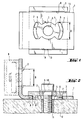
- FIG. 1 shows a cover plate 3 of a fastening device in connection with an angular component 1, which has an opening 2, which consists of a circular hole and two diametrically opposite extensions 7 put together.
- the extensions 7 are symmetrical and one parallel to The axis of symmetry of the extensions 7 measured width B increases towards the outside.
- the cover plate 3 covering the opening 2 with the exception of the passage opening 5 has on one flat side 4 two diametrically opposite projections 6, at least their contour running perpendicular to the flat side 4 of the cover plate 3 a part of the circumferential contour of the extensions 7 of the opening 2 of the component 1 corresponds.
- the flat side 4 of the cover plate 3, which has projections 6, faces the component 1 cooperating guides 8 which are diametrically opposed to each other Reach over side areas 13 of component 1.
- FIG. 2 shows the complete fastening device with cover plate 3 and Fastening element 10 in connection with a component 1, a base 12 and a profile rail 9.
- a fastener 10 in the form of a screw protrudes through the Passage opening 5 of the cover plate 3 and the circular bore of one of the openings 2 of the angular component 1 in a dowel element arranged in the base 12 11.
- the projections 6 arranged on the flat side 4 of the cover plate 3 protrude at least partially in the extensions 7 of the component 1.
- the head of the Fastener 10 is interposed by a washer on that Flat side of the cover plate 3, that of the flat side 4 with the projections 6 opposite.
- the component 1 is with a schematically illustrated profile rail 9 Connected using a schematically illustrated screw connection, a rail nut the screw connection has a non-circular shape corresponding to the opening 2 of the component 1 Head up.
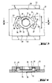
- a cover plate 23 and a plug 29 is another Fastening device shown partially cut.
- the on a component 21 overlying cover plate 23 has a flat side 24, of the projections 26 and Project guides 28 in the form of bent side edges.
- the bent Side edges at least partially overlap the side edges 32 of the component 21.
- the projections 26 lie diametrically opposite one another, the perpendicular to the Flat side 24 of the cover plate 23, at least the contour of the projections 26 corresponds to part of the circumferential contour of the extensions 27 of the opening 22.
- the of a circular bore of the opening 22 of the component 21 outgoing Extensions 27 have a parallel to the symmetry axis of the extensions 27 measured width B, which increases towards the outside.
- a with the cover plate 23 in connection plug-in 29 consists in essentially of an elastic ring 33, two of which are diametrically opposed to each other protrude opposite pin-shaped connecting elements 30.
- the size of one central through bore 34 of the ring 33 corresponds essentially to the size the round passage opening 25 of the cover plate 23.
- Pin-shaped connecting elements 30 protrude into corresponding, diametrically opposite receiving bores 31 of the cover plate 23. Grip edges protruding radially into the receiving bores 31 when the two parts are plugged together into at least partially circumferential ones Wells of the pin-shaped connecting elements 30. In this way, a snap-in axial fixing of the plug-in part 29 on the cover plate 23 is achieved.
- the outer contour of the elastic ring 33 projects in the relaxed state External contour of the circular bore of the opening 22 of the component 21 partially and is radially compressed when inserted into the circular hole. The The resulting preload creates friction on the inner wall of the circular hole. This friction is sufficient to cover plate 23 on the component 21 to be able to pre-assemble.
Landscapes
- Engineering & Computer Science (AREA)
- General Engineering & Computer Science (AREA)
- Mechanical Engineering (AREA)
- Connection Of Plates (AREA)
- Underground Structures, Protecting, Testing And Restoring Foundations (AREA)
- Mutual Connection Of Rods And Tubes (AREA)
- Flanged Joints, Insulating Joints, And Other Joints (AREA)
- Paper (AREA)
- Pressure Vessels And Lids Thereof (AREA)
- Joining Of Building Structures In Genera (AREA)
Description
- Fig. 1
- eine Abdeckplatte der erfindungsgemässen Befestigungsvorrichtung in Verbindung mit einem winkelförmigen Bauteil;
- Fig. 2
- die komplette Befestigungsvorrichtung in Verbindung mit einem Bauteil, einem Untergrund und einer Profilschiene;
- Fig. 3
- eine Abdeckplatte und Vorsteckteil einer weiteren erfindungsgemässen Befestigungsvorrichtung, in Verbindung mit einem leistenförmigen Bauteil;
- Fig. 4
- einen Schnitt durch die Fig. 3 entlang der Linie IV-IV.
Claims (6)
- Befestigungsvorrichtung zum Befestigen eines Bauteiles (1,21), mit einem Befestigungselement (10) und einer Abdeckplatte (3, 23) in Verbindung mit dem eine Öffnung (2, 22) mit unrundem Querschnitt aufweisenden Bauteil (1, 21), dessen Öffnung (2, 22) sich aus einer runden Bohrung mit zwei symmetrisch ausgebildeten, einander diametral gegenüberliegenden Erweiterungen (7, 27) zusammensetzt, deren parallel zur Symmetrieachse der Erweiterungen (7, 27) gemessene Breite (B) nach aussen hin zunimmt, wobei die Abdeckplatte (3, 23) die Öffnung (2, 22) wenigstens teilweise abdeckt und eine runde Durchtrittsöffnung (5, 25) sowie auf einer Flachseite (4, 24) beidseits der Durchtrittsöffnung (5, 25) zwei einander diametral gegenüberliegende, in die Erweiterungen (7, 27) der Öffnung (2, 22) des Bauteiles (1, 21) einfügbare Vorsprünge (6, 26) aufweist, dadurch gekennzeichnet, dass in Richtung Plattenebene die Aussenkontur der Vorsprünge (6, 26) von der Aussenkontur der Abdeckplatte (3, 23) überragt wird.
- Befestigungsvorrichtung nach Anspruch 1, dadurch gekennzeichnet, dass die Abdeckplatte (3, 23) an der Flachseite (4, 24) mit dem Bauteil (1, 21) zusammenwirkende Führungen (8, 28) aufweist.
- Befestigungsvorrichtung nach Anspruch 2, dadurch gekennzeichnet, dass die Führungen (8, 28) von abgebogenen Seitenrandem der Abdeckplatte (3, 23) gebildet sind.
- Befestigungsvorrichtung nach Anspruch 2 oder 3, dadurch gekennzeichnet, dass zwei parallel zueinander verlaufende Führungen vorgesehen sind.
- Befestigungsvorrichtung nach Anspruch 1 bis 4, dadurch gekennzeichnet, dass die Abdeckplatte (23) ein mit dem Bauteil (21) in Verbindung bringbares Vorsteckteil (29) aufweist.
- Befestigungsvorrichtung nach Anspruch 5, dadurch gekennzeichnet, dass das Vorsteckteil (29) parallel zur Flachseite (24) des Bauteiles (21) wenigstens teilweise federbar ist und im entspannten Zustand die Aussenkontur der Öffnung (22) des Bauteiles (21) wenigstens teilweise übersteigt.
Applications Claiming Priority (2)
| Application Number | Priority Date | Filing Date | Title |
|---|---|---|---|
| DE4437648 | 1994-10-21 | ||
| DE4437648A DE4437648A1 (de) | 1994-10-21 | 1994-10-21 | Befestigungsvorrichtung zum Befestigen von Bauteilen an Profilschienen |
Publications (2)
| Publication Number | Publication Date |
|---|---|
| EP0708261A1 EP0708261A1 (de) | 1996-04-24 |
| EP0708261B1 true EP0708261B1 (de) | 1998-04-08 |
Family
ID=6531355
Family Applications (1)
| Application Number | Title | Priority Date | Filing Date |
|---|---|---|---|
| EP95810537A Expired - Lifetime EP0708261B1 (de) | 1994-10-21 | 1995-08-30 | Befestigungsvorrichtung zum Befestigen von Bauteilen |
Country Status (8)
| Country | Link |
|---|---|
| US (1) | US5577860A (de) |
| EP (1) | EP0708261B1 (de) |
| JP (1) | JP3814316B2 (de) |
| CN (1) | CN1058326C (de) |
| AT (1) | ATE164925T1 (de) |
| CA (1) | CA2161035C (de) |
| DE (2) | DE4437648A1 (de) |
| ES (1) | ES2114291T3 (de) |
Families Citing this family (24)
| Publication number | Priority date | Publication date | Assignee | Title |
|---|---|---|---|---|
| US6213679B1 (en) * | 1999-10-08 | 2001-04-10 | Super Stud Building Products, Inc. | Deflection slide clip |
| JP2002181024A (ja) | 2000-12-15 | 2002-06-26 | Nec Corp | ネジ止め構造 |
| US20040062624A1 (en) * | 2002-09-26 | 2004-04-01 | Intel Corporation | Vented cold ring, processes, and methods of using |
| DE10256546A1 (de) * | 2002-12-04 | 2004-06-24 | Hilti Ag | Befestigungselement |
| US7104024B1 (en) * | 2003-10-20 | 2006-09-12 | The Steel Network, Inc. | Connector for connecting two building members together that permits relative movement between the building members |
| US7503150B1 (en) * | 2003-10-20 | 2009-03-17 | The Steel Network, Inc. | Connector assembly for allowing relative movement between two building members |
| US7891144B2 (en) * | 2004-08-04 | 2011-02-22 | Simpson Strong-Tie Company, I{umlaut over (n)}c. | Adjustable heavy girder tiedown |
| US7716877B2 (en) * | 2004-08-04 | 2010-05-18 | Simpson Strong-Tie Co., Inc. | Girder tiedown |
| US20060032183A1 (en) * | 2004-08-16 | 2006-02-16 | Peterson Neal L | Construction member |
| US7478508B2 (en) * | 2004-08-16 | 2009-01-20 | Scafco Corporation | Mounting clip |
| US7707785B2 (en) | 2006-10-31 | 2010-05-04 | Simpson Strong-Tie Company, Inc. | Variable girder tie |
| US7520693B2 (en) * | 2007-02-15 | 2009-04-21 | Denso International America, Inc. | Screw boss with snap fitting |
| US8555592B2 (en) | 2011-03-28 | 2013-10-15 | Larry Randall Daudet | Steel stud clip |
| US9534371B2 (en) * | 2012-03-27 | 2017-01-03 | Steven G. Judd | Framing system for steel stud framing |
| JP6191959B2 (ja) * | 2013-10-18 | 2017-09-06 | パナソニックIpマネジメント株式会社 | 発光装置、照明用光源及び照明装置 |
| CN103661609B (zh) * | 2013-12-29 | 2016-03-02 | 长城汽车股份有限公司 | 一种汽车车身与副车架安装结构 |
| USD732708S1 (en) | 2013-12-30 | 2015-06-23 | Simpson Strong-Tie Company | Flared joist and rafter connector |
| USD730545S1 (en) | 2013-12-30 | 2015-05-26 | Simpson Strong-Tie Company | Joist and rafter connector |
| US9091056B2 (en) | 2013-12-31 | 2015-07-28 | Simpson Strong-Tie Company, Inc. | Multipurpose concrete anchor clip |
| CA2942452C (en) | 2016-01-20 | 2023-08-01 | Simpson Strong-Tie Company, Inc. | Slide clip connector |
| WO2018045334A1 (en) | 2016-09-02 | 2018-03-08 | Simpson Strong-Tie Company, Inc. | Building structural connection comprising an angular bracket |
| US11078682B1 (en) | 2016-12-19 | 2021-08-03 | The Steel Network, Inc. | Connector assembly for allowing relative movement between two building members |
| CN109654109A (zh) * | 2019-01-30 | 2019-04-19 | 中国铁建重工集团有限公司 | 安装支座及掘进设备 |
| CN114962426B (zh) * | 2022-05-18 | 2023-09-26 | 中航沈飞民用飞机有限责任公司 | 一种于斜面上保证螺栓与结构孔同轴度的装置 |
Citations (2)
| Publication number | Priority date | Publication date | Assignee | Title |
|---|---|---|---|---|
| EP0400347A2 (de) * | 1989-05-31 | 1990-12-05 | TRW STEERING & INDUSTRIAL PRODUCTS (JAPAN) CO., LTD. | Unterlegscheibe |
| DE4243185A1 (de) * | 1992-12-19 | 1994-06-23 | Hilti Ag | Befestigungsvorrichtung |
Family Cites Families (6)
| Publication number | Priority date | Publication date | Assignee | Title |
|---|---|---|---|---|
| US2639789A (en) * | 1947-12-03 | 1953-05-26 | Universal Steel Equipment Corp | Extensible joint structure |
| US3472542A (en) * | 1966-09-28 | 1969-10-14 | Le Roy Hart | Fastener |
| NL8003184A (nl) * | 1980-05-30 | 1982-01-04 | Flamco Bv | Verbindingsorgaan voor het onder een hoek aan elkaar bevestigen van twee holle staafelementen. |
| DE3140459C2 (de) * | 1981-10-12 | 1984-02-09 | Pepperl & Fuchs Gmbh & Co Kg, 6800 Mannheim | Einstellschieber für eine justierbare Anbringung eines Endschalters |
| DE8300961U1 (de) * | 1983-01-15 | 1983-06-09 | E. Winkemann GmbH & Co KG, 5970 Plettenberg | Sechskantschraube oder Sechskantmutter mit Unterlegscheibe |
| US4616950A (en) * | 1984-01-31 | 1986-10-14 | Morris Tom C | Timber joining devices |
-
1994
- 1994-10-21 DE DE4437648A patent/DE4437648A1/de not_active Withdrawn
-
1995
- 1995-08-30 AT AT95810537T patent/ATE164925T1/de active
- 1995-08-30 DE DE59501833T patent/DE59501833D1/de not_active Expired - Lifetime
- 1995-08-30 ES ES95810537T patent/ES2114291T3/es not_active Expired - Lifetime
- 1995-08-30 EP EP95810537A patent/EP0708261B1/de not_active Expired - Lifetime
- 1995-10-18 US US08/544,516 patent/US5577860A/en not_active Expired - Lifetime
- 1995-10-19 CN CN95115995A patent/CN1058326C/zh not_active Expired - Lifetime
- 1995-10-20 CA CA002161035A patent/CA2161035C/en not_active Expired - Lifetime
- 1995-10-23 JP JP27416395A patent/JP3814316B2/ja not_active Expired - Fee Related
Patent Citations (2)
| Publication number | Priority date | Publication date | Assignee | Title |
|---|---|---|---|---|
| EP0400347A2 (de) * | 1989-05-31 | 1990-12-05 | TRW STEERING & INDUSTRIAL PRODUCTS (JAPAN) CO., LTD. | Unterlegscheibe |
| DE4243185A1 (de) * | 1992-12-19 | 1994-06-23 | Hilti Ag | Befestigungsvorrichtung |
Also Published As
| Publication number | Publication date |
|---|---|
| DE59501833D1 (de) | 1998-05-14 |
| EP0708261A1 (de) | 1996-04-24 |
| ATE164925T1 (de) | 1998-04-15 |
| US5577860A (en) | 1996-11-26 |
| CA2161035A1 (en) | 1996-04-22 |
| CN1058326C (zh) | 2000-11-08 |
| CN1124333A (zh) | 1996-06-12 |
| JPH08210323A (ja) | 1996-08-20 |
| CA2161035C (en) | 2004-08-10 |
| ES2114291T3 (es) | 1998-05-16 |
| JP3814316B2 (ja) | 2006-08-30 |
| DE4437648A1 (de) | 1996-04-25 |
Similar Documents
| Publication | Publication Date | Title |
|---|---|---|
| EP0708261B1 (de) | Befestigungsvorrichtung zum Befestigen von Bauteilen | |
| EP0687822B2 (de) | Befestigungsvorrichtung | |
| EP1215401B1 (de) | Vorrichtung zum Verbinden von Bauteilen | |
| EP0604361B1 (de) | Befestigungsvorrichtung | |
| DE69001083T2 (de) | Befestigungsvorrichtung mit einer dichtungsbuchse. | |
| DE2508463C2 (de) | Schnellverbinder | |
| DE69003574T2 (de) | Höheneinstellvorrichtung, insbesondere für Möbel. | |
| EP1626185B1 (de) | Einstelleinheit zum Einstellen des Abstandes zwischen zwei Bauteilen | |
| EP0643232A2 (de) | Mutter mit Druckring | |
| EP0902198A2 (de) | Steckkupplung | |
| DE3843096C2 (de) | Befestigungseinrichtung für Verkleidungen | |
| DE3843095C2 (de) | Befestigungseinrichtung für Verkleidungen | |
| DE102021105786A1 (de) | Toleranzausgleichsanordnung | |
| DE10318023A1 (de) | Schraubelement mit einem angeformten Federelement | |
| DE2708538A1 (de) | Verbindung zwischen den kettengliedern einer gleiskette | |
| DE19503945A1 (de) | Federbelastetes Rückschlagventil | |
| EP1117151A1 (de) | Kabelschuh | |
| DE20213362U1 (de) | Befestigungsanordnung für eine Heckleuchte | |
| EP1013944B1 (de) | Befestigungselement | |
| DE4406291B4 (de) | Übertragungsvorrichtung | |
| EP1279839B1 (de) | Schraubblindniet-Verbindungsanordnung | |
| DE2142488A1 (de) | Lösbarer Schraubverbinddr, insbesondere zum Anschluß von Tafeln an Rahmen od. dgl | |
| EP1081296A1 (de) | Sanitärarmatur | |
| EP0646748B1 (de) | Ringstutzenkupplung für Fluide | |
| EP1039153B1 (de) | Vormontierte Befestigungseinheit |
Legal Events
| Date | Code | Title | Description |
|---|---|---|---|
| PUAI | Public reference made under article 153(3) epc to a published international application that has entered the european phase |
Free format text: ORIGINAL CODE: 0009012 |
|
| AK | Designated contracting states |
Kind code of ref document: A1 Designated state(s): AT CH DE ES FR GB LI |
|
| 17P | Request for examination filed |
Effective date: 19960523 |
|
| 17Q | First examination report despatched |
Effective date: 19961108 |
|
| GRAG | Despatch of communication of intention to grant |
Free format text: ORIGINAL CODE: EPIDOS AGRA |
|
| GRAG | Despatch of communication of intention to grant |
Free format text: ORIGINAL CODE: EPIDOS AGRA |
|
| GRAH | Despatch of communication of intention to grant a patent |
Free format text: ORIGINAL CODE: EPIDOS IGRA |
|
| GRAH | Despatch of communication of intention to grant a patent |
Free format text: ORIGINAL CODE: EPIDOS IGRA |
|
| GRAA | (expected) grant |
Free format text: ORIGINAL CODE: 0009210 |
|
| AK | Designated contracting states |
Kind code of ref document: B1 Designated state(s): AT CH DE ES FR GB LI |
|
| REF | Corresponds to: |
Ref document number: 164925 Country of ref document: AT Date of ref document: 19980415 Kind code of ref document: T |
|
| REG | Reference to a national code |
Ref country code: CH Ref legal event code: EP |
|
| REF | Corresponds to: |
Ref document number: 59501833 Country of ref document: DE Date of ref document: 19980514 |
|
| REG | Reference to a national code |
Ref country code: ES Ref legal event code: FG2A Ref document number: 2114291 Country of ref document: ES Kind code of ref document: T3 |
|
| ET | Fr: translation filed | ||
| GBT | Gb: translation of ep patent filed (gb section 77(6)(a)/1977) |
Effective date: 19980616 |
|
| PLBE | No opposition filed within time limit |
Free format text: ORIGINAL CODE: 0009261 |
|
| STAA | Information on the status of an ep patent application or granted ep patent |
Free format text: STATUS: NO OPPOSITION FILED WITHIN TIME LIMIT |
|
| 26N | No opposition filed | ||
| REG | Reference to a national code |
Ref country code: GB Ref legal event code: IF02 |
|
| PGFP | Annual fee paid to national office [announced via postgrant information from national office to epo] |
Ref country code: DE Payment date: 20140827 Year of fee payment: 20 Ref country code: CH Payment date: 20140812 Year of fee payment: 20 |
|
| PGFP | Annual fee paid to national office [announced via postgrant information from national office to epo] |
Ref country code: FR Payment date: 20140808 Year of fee payment: 20 Ref country code: ES Payment date: 20140711 Year of fee payment: 20 Ref country code: AT Payment date: 20140728 Year of fee payment: 20 Ref country code: GB Payment date: 20140827 Year of fee payment: 20 |
|
| REG | Reference to a national code |
Ref country code: DE Ref legal event code: R071 Ref document number: 59501833 Country of ref document: DE |
|
| REG | Reference to a national code |
Ref country code: CH Ref legal event code: PL |
|
| REG | Reference to a national code |
Ref country code: GB Ref legal event code: PE20 Expiry date: 20150829 |
|
| REG | Reference to a national code |
Ref country code: AT Ref legal event code: MK07 Ref document number: 164925 Country of ref document: AT Kind code of ref document: T Effective date: 20150830 |
|
| PG25 | Lapsed in a contracting state [announced via postgrant information from national office to epo] |
Ref country code: GB Free format text: LAPSE BECAUSE OF EXPIRATION OF PROTECTION Effective date: 20150829 |
|
| REG | Reference to a national code |
Ref country code: ES Ref legal event code: FD2A Effective date: 20151204 |
|
| PG25 | Lapsed in a contracting state [announced via postgrant information from national office to epo] |
Ref country code: ES Free format text: LAPSE BECAUSE OF EXPIRATION OF PROTECTION Effective date: 20150831 |