EP0707415B1 - Verbessertes Verfahren und Gerät zur Korrektur heller Farben in Binärdruckvorrichtungen - Google Patents
Verbessertes Verfahren und Gerät zur Korrektur heller Farben in Binärdruckvorrichtungen Download PDFInfo
- Publication number
- EP0707415B1 EP0707415B1 EP95307166A EP95307166A EP0707415B1 EP 0707415 B1 EP0707415 B1 EP 0707415B1 EP 95307166 A EP95307166 A EP 95307166A EP 95307166 A EP95307166 A EP 95307166A EP 0707415 B1 EP0707415 B1 EP 0707415B1
- Authority
- EP
- European Patent Office
- Prior art keywords
- color
- value
- values
- inter
- pixel
- Prior art date
- Legal status (The legal status is an assumption and is not a legal conclusion. Google has not performed a legal analysis and makes no representation as to the accuracy of the status listed.)
- Expired - Lifetime
Links
Images


Classifications
-
- H—ELECTRICITY
- H04—ELECTRIC COMMUNICATION TECHNIQUE
- H04N—PICTORIAL COMMUNICATION, e.g. TELEVISION
- H04N1/00—Scanning, transmission or reproduction of documents or the like, e.g. facsimile transmission; Details thereof
- H04N1/46—Colour picture communication systems
- H04N1/52—Circuits or arrangements for halftone screening
Definitions
- the present invention relates to digital color printing devices, and in particular, to a technique for minimizing artifacts ("erroneous colored dots") in the printed output of such devices, which artifacts are caused by error diffusion halftoning.
- CMY cyan
- M magenta
- Y yellow
- B blue
- R red
- K black
- Pictorial images such as those produced by photographic techniques or by computerized imaging systems, by contrast, are continuous in tonality. If such an image is divided into pixels, each pixel exhibits a "grayscale” color whose tonal value falls within a range of tonal values.
- the images In order to reproduce such "continuous-tone" images by means of electronic printing, the images must therefore be converted into a form which is suited to the characteristics of the printing device, generally a binary format. This conversion process, which may take many forms, is generically referred to as "halftoning.” Although a halftone image actually consists solely of a spatial pattern of binary pixels (colored or blank dots), the human visual system integrates this pattern to create an illusion of a continuous-tone image.
- the image to be printed is divided into a series of pixels and the value of the image in each pixel is quantized to produce a multi-bit digital word which represents the tonal value of the pixel.
- the image is thus converted to a stream of digital words which is provided to the printing device.
- halftoning is performed on the digital word stream during a process called "preprocessing".
- preprocessing Numerous halftoning techniques have been developed and refined over the years. In their simplest form, such techniques compare the value of each digital word with a threshold level, and generate a binary output pixel value depending on the relative values.
- a digital scanner processing a continuous-tone image generates a stream of multi-bit words representing the detected light intensities, i.e., pixel tonal values, typically for the colors RGB.
- the numerical value of these words generally ranges from 0 to 255 corresponding to a 256-level gray scale or an 8-bit word.
- the halftoning process typically compares the scanner output words with a single threshold value to produce the required binary output pixel stream.
- the fixed threshold value may be 128 for a grayscale value range between 0 and 255).
- each 8-bit scanner word has effectively been compressed into a single-bit output word.
- the lowest of the three RGB input color values is selected and replaced with K; thereafter, that lowest selected value is subtracted from the remaining two input color values.
- the values of the RGB output words from the digital scanner are: R G B 100 50 30
- application of the undercolor removal technique produces the following sequence: R G B K 70 20 0 30
- This diffusion is performed individually on each of the resulting colors by adding a portion of the quantization error to the input values of the next pixel in the processing line and to neighboring pixels in the following line.
- the quantization error is added to the pixel values before processing so that the quantization error is "spread" over several pixels.
- R represents the maximum color among the three input color values of RGB.
- the values of the RGB color pixels may be: R G B 120 140 10
- a green dot is produced in what should be a predominantly red area.
- This green dot, or "artifact” reduces the vividness of the red color in the resulting image and thus reduces the quality of that image.
- EP-A-0 570 139 describes a process in which the colours for printing a particular pixel are limited to the dominant and the subdominant color of that pixel before error diffusion.
- the pixel could be printed as R or G but not as B, irrespective of the pixel color values after error diffusion.
- Another object of the present invention is to provide apparatus and a method of improving the quality of the halftone images produced by a binary printing device.
- Still another object of the invention is to provide a method and apparatus which minimizes image artifacts due to error diffusion halftoning in the output images produced by a binary printing device, such as a color ink jet printer or laser printer.
- Still yet another object of the invention is to provide such a method which can be implemented relatively easily either in specialized hardware or in existing printer drivers.
- this invention provides a method as set out in claim 1.
- this invention provides an apparatus as set out in claim 7.
- this invention provides a computer system as set out in claim 14.
- this invention provides a method as set out in claim 15.
- the invention resides in a color correction technique for eliminating artifacts from predetermined tonal areas of a halftone image to thereby improve the color vividness of that image, and in apparatus employing the technique.
- artifacts are generally caused by the accumulation of diffusion errors which, after halftoning operations, produce colors that adversely affect the hue of the image.
- the vivid color correction technique described herein identifies these adverse colors and adjusts their values to reflect acceptable colors for those image areas.
- pixel tonal values associated with three input colors are initially examined to determine a maximum color value.
- the resulting binary pixel values are collectively processed to generate inter-color information for comparison with a selected harmonic color cluster.
- the selected cluster is preferably chosen from a plurality of predefined harmonic color clusters in response to the maximum input color value.
- the inter-color information specifies a color that matches one of the colors of the selected harmonic cluster, thereby indicating an acceptable color, no further processing is required and the binary pixel values are passed to an output buffer for printing. On the other hand, if the specified color does not match one of the cluster colors, then the inter-color information is "corrected" to reflect acceptable output color values.
- the inter-color information comprises three bits of data (one for each input color) and the correction process involves transposing the value of one of these bits such that it is equal to the value of the remaining two bits.
- Such correction results in additional error that is subsequently diffused among neighboring pixels to compensate for the corrected output color values. This, although individual pixel values in a predetermined tonal area may be modified, the average values of the pixels in that area do not change.
- the inventive method can be incorporated easily into the driver software of a printing device at relatively little cost or embodied in specialized hardware in the printer port or the printer itself.
- high-quality halftone images can be produced by means of error diffusion halftoning with minimized artifacts.
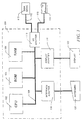
- FIG. 1 illustrates a typical hardware configuration of a computer 100 in accordance with the subject invention.
- the computer 100 is controlled by a central processing unit (CPU) 102, which may be a conventional microprocessor; a number of other units, all interconnected via a system bus 108, are provided to accomplish specific tasks.
- CPU central processing unit
- computer 100 shown in Figure 1 includes a random access memory (RAM) 106 for temporary storage of information, a read only memory (ROM) 104 for permanent storage of the computer's configuration and basic operating commands and an input/output (I/O) adapter 110 for connecting peripheral devices such as a disk unit 113 and printer 114 to the bus 108, via cables 112 and 115, respectively.
- a user interface adapter 116 is also provided for connecting input devices, such as a keyboard 120 and other known interface devices including mice, speakers and microphones, to the bus 108.
- Visual output is provided by a display adapter 118 which connects the bus 108 to a display device 122 such as a video monitor.
- the computer 100 has resident thereon, and is controlled and coordinated by, an operating system.
- a computer system such as that shown in Figure 1 generally includes a printing device which is electrically connected to the computer system and controlled by it in order to generate a permanent image on a selected medium.
- a printing device which is electrically connected to the computer system and controlled by it in order to generate a permanent image on a selected medium.
- the print medium generally has a fixed size
- the printable information must be divided into pieces which are small enough to fit on the selected medium, a process which is called pagination.
- the information may need to be reformatted from the format in which it is either displayed or stored into a format which is suitable for controlling the printing device to actually perform the printing on the medium.
- the reformatting in this latter step may include a preprocessing step in which a graphical display is converted into the form used by the printing device by the halftoning operations discussed above.
- the pagination and reformatting necessary to convert the printable information into a form which can be printed by a given printing device can be performed by specialized hardware, but are generally performed by software programs running within the computer system.
- the pagination is performed by either an application program which generated the initial output or by an operating system which is a collection of utility programs that perform basic file manipulation functions.
- the reformatting, including the undercolor removal and halftoning operations described above, are specific to the printing device and are usually contained in a software program called a "driver" which may be part of the operating system, but must be specifically associated with a particular printing device.
- the driver program receives textual and image information from the computer system and performs such processing operations to generate signals that can directly control the printing device.
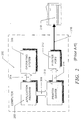
- Figure 2 is a schematic illustration of a typical computer system utilizing an application program, an operating system and a printer driver.
- the computer system is schematically represented by dotted box 200
- the application program is represented by box 202
- the operating system by box 206.
- the interaction between the application program 202 and the operating system 206 is illustrated schematically by arrow 204.
- This dual program system is used on many types of computer systems ranging from mainframes to personal computers.
- the method for handling printing varies from computer to computer, and, in this regard, Figure 2 represents a typical prior art personal computer system.
- the application program 202 interacts (as shown schematically by arrow 208) with printer driver software 210.
- the printer driver software 210 performs undercolor removal and halftoning operations to convert the multi-bit words representing numerical tonal values of typical input color pixels (e.g., RGB) into a binary output pixel stream representing selected of the colors RGBK.
- the driver software 210 may perform other operations to produce a reformatted information stream containing embedded commands and converted graphical information as shown schematically as arrow 214.
- the converted information stream is, in turn, applied to a printer port 212 which contains circuitry that converts the incoming information stream into electrical signals.
- the signals are then sent over a cable 216 to the printer 218.
- Printer 218 usually contains an "imaging engine” which is a hardware device or a ROM-programmed computer which takes the incoming information stream and converts it into the electrical signals necessary to drive the actual printing elements. The result is a "hard copy" output on the selected medium.
- the apparatus which performs the error diffusion process may also be incorporated into specialized hardware located in the printer port 212 of the printer 218 itself.
- Figure 4 illustrates diffusion of the error generated during the processing of each pixel to neighboring pixels in the case where processing proceeds along the line in the left-to-right direction.
- each pixel is processed by comparing its value to a predetermined threshold value where the pixel "value" is the original gray scale value plus error adjustments resulting from the previous processing of other pixels.
- the fixed threshold value may be 128 for a gray scale value range between 0 and 255. If the value of the pixel exceeds the threshold value, then a "1" or dot is output. Alternatively, if the value of the pixel is less than the threshold value, then a "0" or no dot is output. An error value is then determined by subtracting the value of the dot which is actually output from the input value. This error is then "diffused” or spread among neighboring, but unprocessed, pixels.
- FIG. 4 This "diffusion" process is illustrated in Figure 4 where the pixel being processed is depicted as box 400.
- the error resulting from the processing is spread to the neighboring pixel to the immediate right of the processed pixel 400 (as indicated by arrow 402) and to three neighboring pixels on the next line of binary pattern pixels as indicated by arrows 404, 406 and 408.
- the error value is multiplied by a proportionality constant.
- RGB input color pixels have the following tonal values: R G B 100 50 30
- R has a maximum value among the three input colors and, as may be expected, it is desired that R maintain that relationship with those input colors throughout the pre-processing operations performed prior to outputing the processed color values to the printing device. Since, as a result of halftoning, each input color may assume a binary value of either "0" or "1", the possible binary combinations (and their resulting colors) associated with the input colors are: R G B 0 0 0 (K) 0 0 1 (B) 0 1 0 (G) 0 1 1 (C) 1 0 0 (R) 1 0 1 (M) 1 1 0 (Y) 1 1 1 (W)
- R is not a maximum value (i.e., R does not assume a value of "1") for the colors BGC and, significantly, these latter colors function to adversely affect the hue of R.
- R does assume a maximum value for the colors MY, indicating that they do not alter the hue of R, and these colors are therefore referred to as "compatible" colors.
- BGC are "adverse" colors that should be avoided when printing an image.
- the accumulated error values from previously processed pixels may transform the input tonal values of Table 1 into the following tonal values: R G B 80 130 135
- the resulting halftone pattern is: R G B 0 1 1
- Figure 5 is a schematized "rule" graph 500 illustrating groups of dominant input colors (Rmax, Gmax and Bmax) and their associated compatible colors.
- these groups represent predefined harmonic color clusters for use with the vivid color correction technique.
- B is the maximum input color value
- CM are compatible colors as indicated by the dotted circle enclosing the harmonic color cluster 510.
- the colors CY conform to a maximum input pixel value for the color G as indicated by the dotted-segmented circle enclosing the cluster 520.
- Graph 500 also depicts colors that adversely affect the hue of these maximum input colors. Specifically, the adverse colors are those colors not encircled for a particular maximum input color value. Thus, for a Bmax input pixel area, the colors RYG are adverse colors and for a Gmax input pixel area, the colors BRM should be avoided.
- the colors K and W are not shown on the graph of Figure 5 primarily because they do not impact the hue of the input colors, although they do affect the brightness of those colors. Nevertheless, the colors K and W are utilized in accordance with the color correction technique when correcting the adverse colors. Specifically, the vivid color correction technique identifies these adverse colors and thereafter "corrects" their tonal values to reflect acceptable colors for a particular tonal area.
- FIGS 6A and 6B are illustrative flowcharts of the novel color correction routine executed in accordance with the printer driver software.
- the routine starts at Step 600 and proceeds to Step 602 where pixel tonal values associated with three (RGB) input colors are examined to determine the maximum color value.
- Conventional error diffusion halftoning operations are then performed on each pixel in Step 604 and, in Step 606, the resulting binary pixel values are combined to generate inter-color information.
- Step 608 the inter-color information is compared with a harmonic color cluster that is selected from the predefined harmonic color clusters of Figure 5 in response to the determined maximum input color value.
- Step 610 it is determined whether the inter-color information specifies a color that matches one of the colors of the selected harmonic cluster. If so, thereby indicating an acceptable color, the routine proceeds to Step 612 where no further processing is required and the binary pixel values comprising the inter-color information are passed to an output buffer for printing. The routine then finishes at Step 614. On the other hand, if the specified color does not match one of cluster colors, then the routine passes to Step 616 where the inter-color information is corrected to reflect an acceptable output color value.
- the inter-color information comprises three bits of data (one for each input color).
- the value of one of these bits is transposed to its complement such that its value is equal to the values of the remaining two bits.
- the colors BGC are adverse colors for a pixel area where R is the maximum input value. These colors are represented by the following inter-color information: R G B 0 0 1 (B) 0 1 0 (G) 0 1 1 (C)
- the value of the "non-majority" bit is converted to the values of the remaining two bits to generate the following corrected output values: R G B 0 0 0 (K) 0 0 0 (K) 1 1 1 (W)
- the vivid color correction technique converts the adverse colors to one of the colors K or W.
- these latter colors do not alter the hue of the dominant R color and, thus, they are considered acceptable colors despite changing the brightness of that color.
- the conversion to the color K or W results in additional error that must be diffused among neighboring pixels to compensate for the corrected output color values, as indicated in Step 620.
- This error can be expressed as the difference between the input tonal value and the output tonal value after halftoning (as a grayscale value):
- Rout is then converted to "1", thereby adjusting its gray scale tonal value to 255.
- the resulting additional error Rerr is equal to 80 - (255) or -175; this is the additional error that must be diffused among neighboring pixels. It can be appreciated that although individual pixel values in the predetermined tonal area may be modified, the average value of the pixels in that area do not change.
- the routine then proceeds to Step 622 where the corrected binary output pixel values are passed to the output buffer for printing and the routine finishes at Step 624.
- FIG. 7 is an illustrative schematic block diagram depicting an error diffusion halftoning circuit modified in accordance with the principles of the invention.
- error diffusion halftoning circuits 700a-c one for each RGB color pixel input.
- the error diffusion circuit receives a stream 702 of input grayscale image pixels represented by digital words from an imaging device (not shown) in a conventional manner.
- the stream of image pixels is received by a pixel detection and control circuit 704 that is configured to control various elements of the circuit 700a.
- the pixel detection and control circuit 704 interacts with similar circuits of the error diffusion halftoning circuits 700b,c to collectively determine the maximum value among the three input image pixels and, in response to this determination, generate appropriate control signals for enabling logical operations within color correction circuits (such as circuit 720), as described further herein.
- Buffer 706 is, in general, of sufficient size to store incoming image pixel words for an entire line of pixels although other buffer sizes are contemplated within the teachings of the invention. Buffer 706 is, in turn, controlled by buffer control circuit 708 (as indicated schematically by arrow 710) to output the stored values, in line order, to a summing circuit 712 that is configured to diffuse "error" values produced by the processing of previous pixels as described further below.
- buffer 706 can serially output the stored pixel data in a "left-to-right” order (last-in, first-out) in addition to outputing the stored pixel data in a "right-to-left” order (first-in, first-out), if desired.
- the stored input data produced at the output of input buffer 706 is applied to a threshold circuit 716 by way of summing circuit 712 and line 714.
- the output of threshold circuit 716 is a quantized binary image (comprised of "0's” and “1's") which is produced by comparing the pixel values (each pixel "value” comprises the original input image value and "error” adjustments introduced by summing circuit 712) with a predetermined, fixed threshold value and outputting a "1” if the pixel value is greater than the threshold and outputting a "0” if the pixel value is less than or equal to the threshold value.
- the threshold circuit 716 may use a fixed threshold value such as 0.5 (for a grayscale value range between 0 and 1) or 128 (for a grayscale value range between 0 and 255).
- the quantized binary signal generated by the threshold circuit 716 is fed to a color correction circuit 720 according to the invention.
- the circuit 720 preferably operates in conjunction with similar circuits of the error diffusion halftoning circuits 700b,c to collectively process the binary signal values generated by respective threshold circuits to generate inter-color information for comparison with a selected harmonic color cluster.
- the selected cluster is preferably chosen from the plurality of predefined harmonic color clusters shown in Figure 5. Accordingly, the pixel detection and control circuit 704 generates a control signal over line 722 to circuit 720 for selecting an appropriate cluster in response to the maximum input color value.
- circuits 704 and 720 contain circuitry (e.g., comparators, inverters, registers, etc.) needed to implement the logical operations set forth in the routine of Figure 6 in order to generate correct binary pixel values.
- circuitry e.g., comparators, inverters, registers, etc.
- the binary output value generated by the color correction circuit 720 is applied, via output line 724, to a second summing circuit 726 which subtracts this quantized binary signal value from the unquantized input signal on line 725 to generate a quantization error value on line 728.
- This quantization error value is applied to filter circuit 730 which multiplies the error value by proportionality coefficients to generate diffused error values on line 736 for storage in error buffer 738. These diffused error values are subsequently added to predetermined neighboring pixels by summing circuit 712 during processing of the next line of pixels.
- the diffused error values can also be added to neighboring pixels in the same line.
- Error buffer 738 is also controlled by buffer control circuit 708 (as indicated schematically by arrow 740) to output selected stored values to summing circuit 712 via output line 742. Under control of the buffer control circuit 708, error buffer 738 can serially output the stored pixel data in a "left-to-right” order (last-in, first out) or it may output the stored pixel data in a "right-to-left” order (first in, first out) so as to match the error data with the input data being shifted out of input buffer 706.
- buffer control circuit 708 controls both input buffer 706 and error buffer 738 to sequentially provide an input pixel value from buffer 706 to summing circuit 712 and a diffused error value from error buffer 738 to summing circuit 712. This summing circuit then provides sequentially error-diffused values to threshold circuit 716 which generates the quantized output for reception by the color correction circuit 720.
- the output of the color correction circuit 720 is also provided to an output buffer 750 which is also controlled by buffer control circuit 708 (as indicated schematically by arrow 754).
- Output buffer 750 can then output a serial stream of binary pixels for provision to the printing device on line 752.
Claims (15)
- Verfahren zum Verbessern der Farblebendigkeit eines Halbtonbildes, das aus mehreren Strömen von stufenlos getönten Eingangspixeln erzeugt wird, wobei jeder Strom Pixel mit Werten einer spezifischen Tönungsfarbe umfaßt, wobei das Verfahren die Schritte umfaßt:dadurch gekennzeichnet, daß es ferner die Schritte umfaßt:Umsetzen eines ersten Eingangspixels jedes Stroms in einen ersten Binärpixelwert;kollektives Verarbeiten des ersten Binärpixelwerts von jedem Strom, um Zwischenfarbinformationen zu erzeugen;Vergleichen der Zwischenfarbinformationen mit Farbwerten einer ausgewählten harmonischen Farbgruppe, wobei dann, wenn die Zwischenfarbinformationen mit einem Farbwert der ausgewählten harmonischen Farbgruppe übereinstimmen, die Zwischenfarbinformationen ohne weitere Verarbeitung weitergeleitet werden;und, wenn die Zwischenfarbinformationen nicht mit einem Farbwert der ausgewählten harmonischen Farbgruppe übereinstimmen, Korrigieren der Zwischenfarbinformationen, um erste korrigierte Farbwerte zu erzeugen; undBereitstellen der Zwischenfarbinformationen zum Drucken als verarbeitete Halbtonfarbpixelwerte, die die Farblebendigkeit des Halbtonbildes verbessern.
- Verfahren nach Anspruch 1, bei dem der Umsetzungsschritt die Schritte umfaßt:iteratives Vergleichen des Tonwerts jedes ersten Eingangspixels mit einem Schwellenwert;Auswählen eines Binärpixelwertes auf der Grundlage des Vergleichs;elektronisches Speichern eines Fehlerwerts, der die Differenz zwischen dem ersten Eingangspixelwert und dem Schwellenwert definiert; undVerwischen des Fehlerwertes unter den Nachbarpixeln jedes Stroms.
- Verfahren nach Anspruch 1 oder Anspruch 2, das ferner den Schritt des Ermittelns eines maximalen Tönungsfarbwerts unter den ersten Eingangspixeln jedes Stroms umfaßt.
- Verfahren nach Anspruch 1, 2 oder 3, bei dem der kollektive Verarbeitungsschritt ferner den Schritt des Auswählens der gewählten harmonischen Farbgruppe unter mehreren harmonischen Farbgruppen in Reaktion auf den ermittelten maximalen Tönungsfarbwert umfaßt.
- Verfahren nach irgendeinem der vorangehenden Ansprüche, bei dem die Zwischenfarbinformationen 3 Bits umfassen, und bei dem der Korrekturschritt den Schritt des Transponierens des Wertes von einem der 3 Bits umfaßt, derart, daß er den Werten der restlichen 2 Bits gleicht, um somit die Zwischenfarbinformationen auf die korrekt verarbeiteten Halbtonfarbpixelwerte umzusetzen.
- Verfahren nach Anspruch 5, bei dem der Korrekturschritt ferner die Schritte umfaßt:Erzeugen eines zusätzlichen Fehlers in Reaktion auf den Transponierungsschritt; undVerwischen des zusätzlichen Fehlers unter den Nachbarpixeln jedes Stroms.
- Vorrichtung zum Verbessern der Farblebendigkeit eines Halbtonbildes, das aus mehreren Strömen stufenlos getönter Eingangspixel erzeugt wird, wobei jeder Strom Pixel mit Werten einer spezifischen Tönungsfarbe umfaßt, wobei die Vorrichtung umfaßt:dadurch gekennzeichnet, daß die kollektive Verarbeitungseinrichtung eine Farbkorrekturschaltung (720) umfaßt zum Vergleichen der Zwischenfarbinformationen mit Farbwerten einer ausgewählten harmonischen Farbgruppe;eine Einrichtung (716, 738, 730) zum Umsetzen eines ersten Eingangspixels jedes Stroms in einen ersten Binärpixelwert;eine Einrichtung (720) zum kollektiven Verarbeiten des ersten Binärpixelwerts jedes Stroms, um Zwischenfarbinformationen zu erzeugen;eine Einrichtung zum Bereitstellen der Zwischenfarbinformationen für einen Ausgangspuffer (750) zum Drucken als verarbeitete Halbtonfarbpixelwerte, die die Farblebendigkeit des Halbtonbildes verbessern;
und eine Einrichtung zum Korrigieren der Zwischenfarbinformationen, um erste korrigierte Werte zu erzeugen, wenn die Zwischenfarbinformationen nicht mit einem Farbwert der harmonischen Farbgruppe übereinstimmen. - Vorrichtung nach Anspruch 7, die ferner eine Einrichtung (704) umfaßt zum Ermitteln eines maximalen Tönungsfarbwerts unter den ersten Eingangspixeln jedes Stroms.
- Vorrichtung nach Anspruch 7 oder 8, bei der die Zwischenfarbinformationen 3 Bits umfassen, und bei der die Korrektureinrichtung den Wert eines der 3 Bits so transponiert, daß er den Werten der restlichen 2 Bits gleicht, um somit die Zwischenfarbinformationen in korrekt verarbeitete Halbtonfarbpixelwerte umzusetzen.
- Vorrichtung nach irgendeinem der Ansprüche 7 bis 8, die ferner einen Eingangspuffer (706) umfaßt zum Speichern der Tönungspixelwerte einer unmittelbar vorangehenden Serie von Pixeln, wobei die vorher verarbeiteten Pixel aus dem Puffer gewählt werden.
- Vorrichtung nach Anspruch 8, bei der die Ermittlungseinrichtung eine Pixelerfassungs- und Steuerschaltung (704) umfaßt; wobei die Pixelerfassungs- und Steuerschaltung ein Steuersignal erzeugt zum Auswählen der ausgewählten harmonischen Farbgruppe in Reaktion auf den ermittelten maximalen Tönungsfarbenwert.
- Vorrichtung nach irgendeinem der Ansprüche 7 bis 11, bei der die Umsetzungseinrichtung umfaßt:eine Schwellenschaltung (716) zum iterativen Vergleichen des Tönungswerts jedes ersten Eingangspixels mit einem Schwellenwert;einen Fehlerpuffer (738) zum Speichern eines Fehlerwerts, der die Differenz zwischen dem ersten Eingangspixelwert und dem Schwellenwert definiert; undeine Fehlerfilterschaltung (730) zum Verwischen des Fehlerwerts unter den Nachbarpixeln jedes Stroms.
- Vorrichtung nach Anspruch 12, bei der der Fehlerpuffer die Fehlerwerte einer unmittelbar vorausgehenden Serie von Pixeln speichert, und bei der die Fehlerwerte aus dem Fehlerpuffer ausgewählt werden.
- Computersystem (100), mit:dadurch gekennzeichnet, daß es ferner umfaßt:einem Speicher (106) zum Speichern von Daten und Programmen;einer Zentraleinheit (102), die auf die im Speicher programmierten Programme anspricht, um den Betrieb des Computersystems zu steuern und zu koordinieren;einer Digitalisierungseinrichtung, die auf ein stufenlos getöntes Bild anspricht, um einen Strom von elektronisch codierten Pixelwerten zu erzeugen, die jeweils einen Grauskalenwert eines Abschnitts des stufenlos getönten Bildes darstellen;einem Eingangspuffer (706), der auf den Strom der elektronisch codierten Pixelwerte anspricht, um die elektronisch codierten Pixelwerte in mehreren linearen Segmenten zu speichern, wobei jedes lineare Segment Pixelwerte umfaßt, die zusammenhängende Abschnitte des stufenlos getönten Bildes darstellen;eine Pixelerfassungs- und Steuerschaltung (704) zum Ermitteln des maximalen Grauskalenwerts der elektronisch codierten Pixel;eine Fehlerdiffusions-Halbtönungseinrichtung (716, 730, 738) zum Quantisieren der Grauskalenwerte in ein Halbtonmuster und zum Erzeugen von Quantisierungsfehlern, die zum Verwischen unter den benachbarten codierten Pixelwerten des Stroms dienen;eine Farbkorrekturschaltung (720) zum Erzeugen von Zwischenfarbinformationen aus den quantisierten Grauskalenwerten und zum Korrigieren der Zwischenfarbinformationen, um korrigierte Farbwerte zu erzeugen, wenn die Zwischenfarbinformationen nicht mit einem Farbwert einer ausgewählten harmonischen Farbgruppe übereinstimmen, wobei die ausgewählte harmonische Farbgruppe in Reaktion auf den ermittelten maximalen Grauskalenwert ausgewählt wird; undeinen Drucker (114), der auf die korrigierten Farbwerte anspricht, um das Halbtonmuster der monochromen Punkte auf einem Druckmedium auszudrucken, um ein Halbtonbild zu erzeugen.
- Verfahren zum Verbessern der Farblebendigkeit eines Halbtonbildes, das aus mehreren Strömen von stufenlos getönten Eingangspixeln erzeugt wird, wobei jeder Strom Pixel mit Werten einer spezifischen Tönungsfarbe umfaßt, wobei das Verfahren dadurch gekennzeichnet ist, daß es die Schritte umfaßt:Vergleichen der entsprechenden Eingangspixel in jedem Strom, um den maximalen Tönungsfarbwert zu ermitteln;Korrigieren der entsprechenden Eingangspixel in jedem Strom in Binärpixelwerten;Vergleichen der Binärpixelwerte mit dem maximalen Tönungsfarbwert;Korrigieren der Binärpixelwerte, wenn sie mit dem maximalen Tönungsfarbwert inkompatibel sind; undBereitstellen der Binärpixelwerte oder, wenn eine Korrektur vorgenommen wurde, der korrigierten Binärpixelwerte für einen Ausgangspuffer zum Drucken.
Applications Claiming Priority (2)
| Application Number | Priority Date | Filing Date | Title |
|---|---|---|---|
| US08/320,538 US5675716A (en) | 1994-10-11 | 1994-10-11 | Method and apparatus for vivid color correction in binary printing devices |
| US320538 | 1994-10-11 |
Publications (3)
| Publication Number | Publication Date |
|---|---|
| EP0707415A2 EP0707415A2 (de) | 1996-04-17 |
| EP0707415A3 EP0707415A3 (de) | 1997-03-05 |
| EP0707415B1 true EP0707415B1 (de) | 2000-07-26 |
Family
ID=23246872
Family Applications (1)
| Application Number | Title | Priority Date | Filing Date |
|---|---|---|---|
| EP95307166A Expired - Lifetime EP0707415B1 (de) | 1994-10-11 | 1995-10-11 | Verbessertes Verfahren und Gerät zur Korrektur heller Farben in Binärdruckvorrichtungen |
Country Status (4)
| Country | Link |
|---|---|
| US (1) | US5675716A (de) |
| EP (1) | EP0707415B1 (de) |
| JP (1) | JP3309944B2 (de) |
| DE (1) | DE69518129T2 (de) |
Families Citing this family (14)
| Publication number | Priority date | Publication date | Assignee | Title |
|---|---|---|---|---|
| US5710827A (en) * | 1994-09-19 | 1998-01-20 | Hewlett-Packard Company | Halftone dither cell with integrated preferred color matching |
| US5848180A (en) * | 1996-07-01 | 1998-12-08 | Xerox Corporation | Color bitmap generation with background dependent black objects |
| US6118547A (en) * | 1996-07-17 | 2000-09-12 | Canon Kabushiki Kaisha | Image processing method and apparatus |
| US5838885A (en) * | 1996-09-09 | 1998-11-17 | Seiko Epson Corporation | Salt-and-pepper-noise reduction |
| US6825952B1 (en) * | 1998-06-19 | 2004-11-30 | International Business Machines Corporation | Printer calibration scheme |
| US6266155B1 (en) | 1998-06-19 | 2001-07-24 | International Business Machines Corporation | Half-tone screen calibrations |
| US6671835B1 (en) | 2000-05-15 | 2003-12-30 | International Business Machines Corporation | Error detection in digital scanning device having parallel data streams |
| JP4065482B2 (ja) * | 2001-09-18 | 2008-03-26 | キヤノン株式会社 | 画像データ処理方法、装置、記憶媒体、及びプログラム |
| JP4533218B2 (ja) * | 2005-04-06 | 2010-09-01 | キヤノン株式会社 | 画像処理装置、画像処理方法及び画像処理プログラム |
| US20060232821A1 (en) * | 2005-04-15 | 2006-10-19 | Sridharan Ranganathan | Parallel architecture for vector color error diffusion |
| US7620255B2 (en) * | 2005-06-24 | 2009-11-17 | Seiko Epson Corporation | Image processor and image processing program for binary processing |
| US7706606B1 (en) * | 2006-05-31 | 2010-04-27 | Adobe Systems Incorporated | Fast, adaptive color to grayscale conversion |
| JP5299466B2 (ja) * | 2011-04-07 | 2013-09-25 | コニカミノルタ株式会社 | 画像処理装置、画像処理方法及びプログラム |
| CN108353113B (zh) * | 2016-01-29 | 2020-02-07 | 惠普发展公司,有限责任合伙企业 | 误差扩散 |
Family Cites Families (24)
| Publication number | Priority date | Publication date | Assignee | Title |
|---|---|---|---|---|
| US5130935A (en) * | 1986-03-31 | 1992-07-14 | Canon Kabushiki Kaisha | Color image processing apparatus for extracting image data having predetermined color information from among inputted image data and for correcting inputted image data in response to the extracted image data |
| EP0259981B2 (de) * | 1986-08-13 | 1999-05-06 | Canon Kabushiki Kaisha | Verfahren und Vorrichtung zur Verarbeitung von Farbbildern |
| DE3751916D1 (de) * | 1986-12-19 | 1996-10-24 | Matsushita Electric Ind Co Ltd | Gerät zur Verarbeitung von Signalen für die Anzeige von Bildern mit zwei Pegeln |
| US4989079A (en) * | 1987-10-23 | 1991-01-29 | Ricoh Company, Ltd. | Color correction device and method having a hue area judgement unit |
| JPH02192967A (ja) * | 1988-11-01 | 1990-07-30 | Fuji Xerox Co Ltd | 色調整方法および装置 |
| US5051844A (en) * | 1989-01-30 | 1991-09-24 | Eastman Kodak Company | Digital halftoning with error diffusion |
| EP0409474B1 (de) * | 1989-07-17 | 1995-11-29 | Matsushita Electric Industrial Co., Ltd. | Gerät zur Farbbilderzeugung |
| US5119186A (en) * | 1989-09-28 | 1992-06-02 | International Business Machines Corporation | Color mapping system and method |
| US5231515A (en) * | 1989-11-07 | 1993-07-27 | Canon Kabushiki Kaisha | Image reading device |
| DE4002298C2 (de) * | 1990-01-26 | 1995-11-09 | Agfa Gevaert Ag | Verfahren und Vorrichtung zur automatischen Korrektur von Farbstichen bei der elektronischen Bildverarbeitung |
| US5239370A (en) * | 1990-04-24 | 1993-08-24 | Brother Kogyo Kabushiki Kaisha | Color image forming apparatus having color-correcting unit operating in accordance with a gamut of an image input medium |
| JP2666523B2 (ja) * | 1990-05-16 | 1997-10-22 | 松下電器産業株式会社 | 色変換装置 |
| US5202935A (en) * | 1990-10-19 | 1993-04-13 | Matsushita Electric Industrial Co., Ltd. | Color conversion apparatus for altering color values within selected regions of a reproduced picture |
| US5317426A (en) * | 1990-11-26 | 1994-05-31 | Konica Corporation | Color estimation method for expanding a color image for reproduction in a different color gamut |
| KR940009719B1 (ko) * | 1990-12-25 | 1994-10-17 | 니뽕 빅터 가부시끼가이샤 | 칼러 프린터의 색 수정 장치 |
| US5210602A (en) * | 1991-02-25 | 1993-05-11 | International Business Machines Corporation | Coupled-color error diffusion |
| US5394250A (en) * | 1991-03-10 | 1995-02-28 | Canon Kabushiki Kaisha | Image processing capable of handling multi-level image data without deterioration of image quality in highlight areas |
| JP3276985B2 (ja) * | 1991-06-27 | 2002-04-22 | ゼロックス・コーポレーション | イメージピクセル処理方法 |
| US5319473A (en) * | 1991-11-27 | 1994-06-07 | Xerox Corporation | Methods and apparatus for performing real time color gamut compressions |
| US5307182A (en) * | 1991-12-30 | 1994-04-26 | Xerox Corporation | Methods and apparatus for multigeneration color image processing |
| US5333243A (en) * | 1992-05-04 | 1994-07-26 | Hewlett-Packard Company | Method for forming color images, using a hue-plus-gray color model and error diffusion |
| US5296947A (en) * | 1992-10-06 | 1994-03-22 | Cactus | System for softproofing a color reproduction |
| US5515456A (en) * | 1993-10-26 | 1996-05-07 | Visual Edge Technology, Inc. | Process for providing digital halftone image with random error diffusion, color correction and enlargement |
| US5402245A (en) * | 1994-01-27 | 1995-03-28 | Hewlett-Packard Company | Bi-level digital color printer system exhibiting improved undercolor removal and error diffusion procedures |
-
1994
- 1994-10-11 US US08/320,538 patent/US5675716A/en not_active Expired - Fee Related
-
1995
- 1995-10-05 JP JP29465095A patent/JP3309944B2/ja not_active Expired - Fee Related
- 1995-10-11 EP EP95307166A patent/EP0707415B1/de not_active Expired - Lifetime
- 1995-10-11 DE DE69518129T patent/DE69518129T2/de not_active Expired - Lifetime
Also Published As
| Publication number | Publication date |
|---|---|
| EP0707415A3 (de) | 1997-03-05 |
| DE69518129D1 (de) | 2000-08-31 |
| JP3309944B2 (ja) | 2002-07-29 |
| DE69518129T2 (de) | 2000-12-14 |
| JPH08237482A (ja) | 1996-09-13 |
| EP0707415A2 (de) | 1996-04-17 |
| US5675716A (en) | 1997-10-07 |
Similar Documents
| Publication | Publication Date | Title |
|---|---|---|
| US5757976A (en) | Adaptive filtering and thresholding arrangement for reducing graininess of images | |
| EP0707414B1 (de) | Verbessertes Verfahren und Gerät zur Verringerung von Artefakten in Halbtonbildern mit Verwendung von Korrektur des Graugleichgewichts | |
| US6118547A (en) | Image processing method and apparatus | |
| US5325211A (en) | Error diffusion with output and input based feedback | |
| US6393148B1 (en) | Contrast enhancement of an image using luminance and RGB statistical metrics | |
| EP0690612B1 (de) | Verfahren und Gerät zur Verringerung von Störungen in durch Fehlerdiffusion halbtongerasterten Bildern | |
| US6870644B2 (en) | Tone dependent plane dependent error diffusion halftoning | |
| EP0887998B1 (de) | Korrelation von Cyan und Magentaebenen für die Fehlerdiffusionhalbtonrasterung | |
| EP0665679B1 (de) | Digitales Farbdrucksystem | |
| US5883973A (en) | Method and apparatus for processing a document by segmentation into text and image areas | |
| US5963714A (en) | Multicolor and mixed-mode halftoning | |
| EP1073260B1 (de) | Bildverarbeitungsvorrichtung, diese enthaltende Bilderzeugungsvorrichtung und Speichermedium um ein dazu verwendetes Programm zu speichern | |
| US5710827A (en) | Halftone dither cell with integrated preferred color matching | |
| EP0707415B1 (de) | Verbessertes Verfahren und Gerät zur Korrektur heller Farben in Binärdruckvorrichtungen | |
| JP3337187B2 (ja) | 中間調画像において、色彩度を強調するための方法、および装置 | |
| EP0562596A2 (de) | Verfahren und Vorrichtung zur Verarbeitung von Farbbildern | |
| JPH0515105B2 (de) | ||
| US20120113477A1 (en) | Laser print apparatus with dual half tones | |
| US5930010A (en) | Method and apparatus for color halftoning using different halftoning techniques for halftoning different dot planes | |
| US5892596A (en) | Image processing apparatus capable of reforming marker editing | |
| US8159720B2 (en) | Color error diffusion | |
| US6671071B1 (en) | Threshold bias circuits for enhanced color error diffusion | |
| US5809217A (en) | Method and apparatus for deriving additional gray levels in a multi-gray level halftone image | |
| US6693731B1 (en) | Image processing apparatus and method | |
| US20100134809A1 (en) | Gamma correction method for error diffusion |
Legal Events
| Date | Code | Title | Description |
|---|---|---|---|
| PUAI | Public reference made under article 153(3) epc to a published international application that has entered the european phase |
Free format text: ORIGINAL CODE: 0009012 |
|
| AK | Designated contracting states |
Kind code of ref document: A2 Designated state(s): DE FR GB |
|
| PUAL | Search report despatched |
Free format text: ORIGINAL CODE: 0009013 |
|
| AK | Designated contracting states |
Kind code of ref document: A3 Designated state(s): DE FR GB |
|
| 17P | Request for examination filed |
Effective date: 19970822 |
|
| GRAG | Despatch of communication of intention to grant |
Free format text: ORIGINAL CODE: EPIDOS AGRA |
|
| 17Q | First examination report despatched |
Effective date: 19991019 |
|
| GRAG | Despatch of communication of intention to grant |
Free format text: ORIGINAL CODE: EPIDOS AGRA |
|
| GRAH | Despatch of communication of intention to grant a patent |
Free format text: ORIGINAL CODE: EPIDOS IGRA |
|
| GRAH | Despatch of communication of intention to grant a patent |
Free format text: ORIGINAL CODE: EPIDOS IGRA |
|
| GRAA | (expected) grant |
Free format text: ORIGINAL CODE: 0009210 |
|
| AK | Designated contracting states |
Kind code of ref document: B1 Designated state(s): DE FR GB |
|
| REF | Corresponds to: |
Ref document number: 69518129 Country of ref document: DE Date of ref document: 20000831 |
|
| ET | Fr: translation filed | ||
| PLBE | No opposition filed within time limit |
Free format text: ORIGINAL CODE: 0009261 |
|
| STAA | Information on the status of an ep patent application or granted ep patent |
Free format text: STATUS: NO OPPOSITION FILED WITHIN TIME LIMIT |
|
| 26N | No opposition filed | ||
| REG | Reference to a national code |
Ref country code: GB Ref legal event code: IF02 |
|
| PGFP | Annual fee paid to national office [announced via postgrant information from national office to epo] |
Ref country code: FR Payment date: 20101020 Year of fee payment: 16 |
|
| PGFP | Annual fee paid to national office [announced via postgrant information from national office to epo] |
Ref country code: DE Payment date: 20101006 Year of fee payment: 16 |
|
| PGFP | Annual fee paid to national office [announced via postgrant information from national office to epo] |
Ref country code: GB Payment date: 20101006 Year of fee payment: 16 |
|
| GBPC | Gb: european patent ceased through non-payment of renewal fee |
Effective date: 20111011 |
|
| REG | Reference to a national code |
Ref country code: FR Ref legal event code: ST Effective date: 20120629 |
|
| PG25 | Lapsed in a contracting state [announced via postgrant information from national office to epo] |
Ref country code: DE Free format text: LAPSE BECAUSE OF NON-PAYMENT OF DUE FEES Effective date: 20120501 |
|
| REG | Reference to a national code |
Ref country code: DE Ref legal event code: R119 Ref document number: 69518129 Country of ref document: DE Effective date: 20120501 |
|
| PG25 | Lapsed in a contracting state [announced via postgrant information from national office to epo] |
Ref country code: FR Free format text: LAPSE BECAUSE OF NON-PAYMENT OF DUE FEES Effective date: 20111102 Ref country code: GB Free format text: LAPSE BECAUSE OF NON-PAYMENT OF DUE FEES Effective date: 20111011 |