EP0707158A2 - Joint à rotule pour éléments de suspension de véhicules automobiles - Google Patents
Joint à rotule pour éléments de suspension de véhicules automobiles Download PDFInfo
- Publication number
- EP0707158A2 EP0707158A2 EP95115620A EP95115620A EP0707158A2 EP 0707158 A2 EP0707158 A2 EP 0707158A2 EP 95115620 A EP95115620 A EP 95115620A EP 95115620 A EP95115620 A EP 95115620A EP 0707158 A2 EP0707158 A2 EP 0707158A2
- Authority
- EP
- European Patent Office
- Prior art keywords
- ball
- shell
- sliding shell
- elastic material
- ball joint
- Prior art date
- Legal status (The legal status is an assumption and is not a legal conclusion. Google has not performed a legal analysis and makes no representation as to the accuracy of the status listed.)
- Withdrawn
Links
Images


Classifications
-
- F—MECHANICAL ENGINEERING; LIGHTING; HEATING; WEAPONS; BLASTING
- F16—ENGINEERING ELEMENTS AND UNITS; GENERAL MEASURES FOR PRODUCING AND MAINTAINING EFFECTIVE FUNCTIONING OF MACHINES OR INSTALLATIONS; THERMAL INSULATION IN GENERAL
- F16C—SHAFTS; FLEXIBLE SHAFTS; ELEMENTS OR CRANKSHAFT MECHANISMS; ROTARY BODIES OTHER THAN GEARING ELEMENTS; BEARINGS
- F16C11/00—Pivots; Pivotal connections
- F16C11/04—Pivotal connections
- F16C11/06—Ball-joints; Other joints having more than one degree of angular freedom, i.e. universal joints
- F16C11/08—Ball-joints; Other joints having more than one degree of angular freedom, i.e. universal joints with resilient bearings
- F16C11/083—Ball-joints; Other joints having more than one degree of angular freedom, i.e. universal joints with resilient bearings by means of parts of rubber or like materials
- F16C11/086—Ball-joints; Other joints having more than one degree of angular freedom, i.e. universal joints with resilient bearings by means of parts of rubber or like materials with an elastomeric member in the blind end of a socket
-
- F—MECHANICAL ENGINEERING; LIGHTING; HEATING; WEAPONS; BLASTING
- F16—ENGINEERING ELEMENTS AND UNITS; GENERAL MEASURES FOR PRODUCING AND MAINTAINING EFFECTIVE FUNCTIONING OF MACHINES OR INSTALLATIONS; THERMAL INSULATION IN GENERAL
- F16C—SHAFTS; FLEXIBLE SHAFTS; ELEMENTS OR CRANKSHAFT MECHANISMS; ROTARY BODIES OTHER THAN GEARING ELEMENTS; BEARINGS
- F16C11/00—Pivots; Pivotal connections
- F16C11/04—Pivotal connections
- F16C11/06—Ball-joints; Other joints having more than one degree of angular freedom, i.e. universal joints
- F16C11/0619—Ball-joints; Other joints having more than one degree of angular freedom, i.e. universal joints the female part comprising a blind socket receiving the male part
- F16C11/0623—Construction or details of the socket member
- F16C11/0628—Construction or details of the socket member with linings
- F16C11/0633—Construction or details of the socket member with linings the linings being made of plastics
- F16C11/0638—Construction or details of the socket member with linings the linings being made of plastics characterised by geometrical details
-
- B—PERFORMING OPERATIONS; TRANSPORTING
- B60—VEHICLES IN GENERAL
- B60G—VEHICLE SUSPENSION ARRANGEMENTS
- B60G2204/00—Indexing codes related to suspensions per se or to auxiliary parts
- B60G2204/40—Auxiliary suspension parts; Adjustment of suspensions
- B60G2204/416—Ball or spherical joints
-
- B—PERFORMING OPERATIONS; TRANSPORTING
- B60—VEHICLES IN GENERAL
- B60G—VEHICLE SUSPENSION ARRANGEMENTS
- B60G2206/00—Indexing codes related to the manufacturing of suspensions: constructional features, the materials used, procedures or tools
- B60G2206/01—Constructional features of suspension elements, e.g. arms, dampers, springs
- B60G2206/10—Constructional features of arms
- B60G2206/11—Constructional features of arms the arm being a radius or track or torque or steering rod or stabiliser end link
-
- Y—GENERAL TAGGING OF NEW TECHNOLOGICAL DEVELOPMENTS; GENERAL TAGGING OF CROSS-SECTIONAL TECHNOLOGIES SPANNING OVER SEVERAL SECTIONS OF THE IPC; TECHNICAL SUBJECTS COVERED BY FORMER USPC CROSS-REFERENCE ART COLLECTIONS [XRACs] AND DIGESTS
- Y10—TECHNICAL SUBJECTS COVERED BY FORMER USPC
- Y10T—TECHNICAL SUBJECTS COVERED BY FORMER US CLASSIFICATION
- Y10T403/00—Joints and connections
- Y10T403/32—Articulated members
- Y10T403/32606—Pivoted
- Y10T403/32631—Universal ball and socket
- Y10T403/32713—Elastomerically biased or backed components
Definitions
- the invention relates to a ball joint for chassis parts in motor vehicles, in which a joint ball formed on a pivot pin is mounted within a housing in a plastic sliding shell, the outer shell of which closely encloses the housing with an inner shell and has recesses.
- a ball joint with these features is known from DE 38 28 683 - C2-.
- grooves filled with lubricant are provided on the inner sliding surface of the sliding shell, and flat recesses are provided in the area of these grooves on the outer surface of the sliding shell, which enable radial deformation of the sliding shell in the direction toward the housing, in order to thereby cause edge thickening of the inner grooves due to production counteract.
- a similar effect is achieved by a very thin sliding shell wall and ribs arranged on the outside of the sliding shell.
- Multi-part sliding shells made of different elastic materials for ball joints are known from DE-AS 10 14 441.
- Ball joints in which the joint ball is arranged in a liquid-filled hollow body made of elastic material have been disclosed by DE 35 22 013 - A1-.
- the arrangement of an elastic material on the outer contour of the sliding shell compensates for the tolerances without adversely affecting the elasticity of the joint shell.
- the elastic material can be arranged in a ring or only partially on the outer contour of the sliding shell, the extent and cross-sectional shape of the recess filled with highly elastic material being adapted to the respective joint construction and to the expected operating loads on the joint. It is particularly advantageous that the sliding shell can continue to be made in one piece, and thus the advantageous training features obtained over many years of operation can be retained.
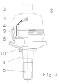
- the ball joint shown in the exemplary embodiments consists of a joint ball 2 formed on one end of a joint pin 1 and a housing 3, in which the joint ball 2 is mounted so that it can slide on all sides by means of a sliding shell 4, the sliding movement between the surface of the joint ball 2 and the Inner surface of the sliding shell 4 takes place.
- the housing 3 encloses the outer jacket of the inner jacket Sliding shell 4 such that the sliding shell 4 is supported radially against the housing 3.
- Fastening means 5 on the pivot pin 1 connect it to a vehicle part, and fastening means 6 enable the housing 3 to be connected to another vehicle part.
- a highly elastic material 7 is arranged in a recess between the outer shell of the sliding shell 4 and the inner shell of the housing 3, which material is advantageously partially or circumferentially formed on the outer periphery of the sliding shell 4.
- this elastic material 7 with a lens-like cross section is arranged approximately in the region of the equator 11 of the joint ball, so that the elastic material extends on both sides of the equatorial plane.
- the elastic material 7 can extend in the circumferential direction of the sliding shell over a more or less large length range, for example it can also be circumferential.
- the shape of the recess accommodating the elastic material 7 can be adapted to different joint constructions and their main operating loads.
- the exemplary embodiment according to FIG. 2 is a ball joint which is predominantly loaded in the axial direction of the pivot pin 1, so that the elastic material 7 is arranged in a region in which essential axial forces are transmitted between the joint ball 2 and the housing 3.
- the elastic material 7 is arranged as a relatively thin layer at certain points or all around.
- FIG. 3 shows an arrangement in which the elastic material 7 both in the region of the cylindrical inner wall of the housing and in the region an axial force-transmitting inclined surface of the housing is arranged in order to allow the elastic material to take effect both with radial and with axial joint loads for tolerance compensation.
- FIG. 4 shows a somewhat different design of the ball joint compared to FIGS. 1 to 3.
- the housing 3 of the ball joint encloses a cylindrical outer wall of the sliding shell with a cylindrical inner wall, a thin layer 7 of highly elastic material being located between the two cylindrical walls .
- the elastic material 7 can be arranged only partially or circumferentially in the circumferential direction.
- the shape of the housing, the ball stud and the sliding shell is different in the exemplary embodiments.
- the design of the closure between the joint ball 2 and the housing 3 is also different.
- the gap between the edge of the open side of the housing from which the joint pin 1 is led out and the joint pin is closed by a sealing bellows 8 made of an elastic material, the bead-shaped end of which is held on the one hand by means of a spring ring 9 or the like in a groove on the housing and on the other hand also by means of a spring ring 10 on the shaft of the pivot pin 1.
Landscapes
- Engineering & Computer Science (AREA)
- General Engineering & Computer Science (AREA)
- Mechanical Engineering (AREA)
- Physics & Mathematics (AREA)
- Geometry (AREA)
- Pivots And Pivotal Connections (AREA)
Applications Claiming Priority (2)
| Application Number | Priority Date | Filing Date | Title |
|---|---|---|---|
| DE4436428 | 1994-10-12 | ||
| DE4436428A DE4436428C2 (de) | 1994-10-12 | 1994-10-12 | Kugelgelenk für Fahrwerksteile in Kraftfahrzeugen |
Publications (2)
| Publication Number | Publication Date |
|---|---|
| EP0707158A2 true EP0707158A2 (fr) | 1996-04-17 |
| EP0707158A3 EP0707158A3 (fr) | 1997-05-28 |
Family
ID=6530568
Family Applications (1)
| Application Number | Title | Priority Date | Filing Date |
|---|---|---|---|
| EP95115620A Withdrawn EP0707158A3 (fr) | 1994-10-12 | 1995-10-04 | Joint à rotule pour éléments de suspension de véhicules automobiles |
Country Status (5)
| Country | Link |
|---|---|
| US (1) | US5601305A (fr) |
| EP (1) | EP0707158A3 (fr) |
| JP (1) | JPH08200351A (fr) |
| KR (1) | KR0177859B1 (fr) |
| DE (1) | DE4436428C2 (fr) |
Families Citing this family (11)
| Publication number | Priority date | Publication date | Assignee | Title |
|---|---|---|---|---|
| DE19747931C1 (de) * | 1997-10-30 | 1999-07-08 | Lemfoerder Metallwaren Ag | Kugelgelenk |
| FR2796354B1 (fr) * | 1999-07-13 | 2001-08-10 | Soc Mecanique Irigny | Boitier cote roue pour direction de vehicule automobile |
| US20030086756A1 (en) * | 2001-11-07 | 2003-05-08 | Trotter Jason K | Modular linkage system |
| US6875388B2 (en) * | 2001-11-07 | 2005-04-05 | Illinois Tool Works Inc. | Method for making a ball and socket joint |
| US6929271B2 (en) | 2001-11-09 | 2005-08-16 | Illinois Tool Works Inc. | Hydraulically compensated stabilizer system |
| DE10201022A1 (de) | 2002-01-11 | 2003-07-24 | Zf Lemfoerder Metallwaren Ag | Kugelgelenk |
| US20070166096A1 (en) * | 2005-06-03 | 2007-07-19 | Lim Chong K | Joint assembly |
| DE102006039861A1 (de) * | 2006-08-25 | 2008-03-13 | Zf Friedrichshafen Ag | Dichtungs- oder Faltenbalg |
| US20080085151A1 (en) * | 2006-10-04 | 2008-04-10 | Pazdirek Jiri V | Light weight ball joint |
| US9476447B2 (en) * | 2008-05-21 | 2016-10-25 | Federal-Mogul Powertrain, Inc. | Ball joint assembly and method of making |
| DE102010043039A1 (de) * | 2010-10-28 | 2012-05-03 | Zf Friedrichshafen Ag | Verfahren zur Herstellung eines Fahrwerkbauteils |
Citations (4)
| Publication number | Priority date | Publication date | Assignee | Title |
|---|---|---|---|---|
| DE1014441B (de) | 1953-06-17 | 1957-08-22 | Ehrenreich & Cie A | Kugelgelenk zum UEbertragen von Lenk- und Steuerkraeften od. dgl., insbesondere fuer Lenk- und Steuergestaenge von Kraftfahrzeugen |
| DE7424445U (de) | 1974-07-18 | 1976-06-16 | A. Ehrenreich & Cie, 4000 Duesseldorf | Kugelschale für Kugelgelenke |
| DE3522013A1 (de) | 1985-06-20 | 1987-01-02 | Trw Ehrenreich Gmbh | Kugelgelenk |
| DE3828683C2 (fr) | 1988-08-24 | 1990-06-07 | Lemfoerder Metallwaren Ag, 2844 Lemfoerde, De |
Family Cites Families (16)
| Publication number | Priority date | Publication date | Assignee | Title |
|---|---|---|---|---|
| DD48114A (fr) * | ||||
| GB814666A (en) * | 1956-03-20 | 1959-06-10 | Howard Clawton Wright Ltd | A new or improved ball joint |
| US2451060A (en) * | 1945-10-22 | 1948-10-12 | Thompson Prod Inc | Joint assembly |
| US3226142A (en) * | 1963-01-10 | 1965-12-28 | Thompson Ramo Wooldridge Inc | Ball joint assembly |
| GB945332A (en) * | 1961-07-03 | 1963-12-23 | Ford Motor Co | Preloaded ball joint |
| DE1296889B (de) * | 1964-04-13 | 1969-06-04 | Juergen Dr Ing | Kugelgelenk, insbesondere fuer Lenk- und Steuergestaenge von Kraftfahrzeugen, bei dem ein Gelenkzapfen mit seinem Kugelkopf in einem elastischen Lagerkoerper allseitig beweglich eingebettet ist |
| FR1504970A (fr) * | 1965-12-14 | 1967-12-08 | Ehrenreich & Cie A | Bague de pression pour joints à rotule |
| US3693999A (en) * | 1970-05-04 | 1972-09-26 | Trw Inc | Rack and pinion steering assembly |
| JPS54671B2 (fr) * | 1972-05-29 | 1979-01-13 | ||
| JPS5328576B2 (fr) * | 1973-07-02 | 1978-08-15 | ||
| GB2053342B (en) * | 1979-07-05 | 1983-04-07 | Automotive Prod Co Ltd | Ball and socket joints |
| EP0075414B1 (fr) * | 1981-09-22 | 1985-11-13 | Automotive Products Public Limited Company | Articulation à rotule |
| GB2155989B (en) * | 1984-03-21 | 1987-02-11 | Quinton Hazell Holdings Ltd | A ball joint |
| JPH0730782B2 (ja) * | 1987-10-30 | 1995-04-10 | 武蔵精密工業株式会社 | ボールジョイント |
| US5165306A (en) * | 1990-10-04 | 1992-11-24 | Maclean-Fogg Company | Vehicle stabilizer bar end link |
| DE4102863C5 (de) * | 1991-01-31 | 2006-01-26 | ZF Lemförder Metallwaren AG | Kugelgelenk für Kraftfahrzeuge |
-
1994
- 1994-10-12 DE DE4436428A patent/DE4436428C2/de not_active Expired - Fee Related
-
1995
- 1995-10-04 KR KR1019950033770A patent/KR0177859B1/ko not_active IP Right Cessation
- 1995-10-04 EP EP95115620A patent/EP0707158A3/fr not_active Withdrawn
- 1995-10-09 JP JP7261407A patent/JPH08200351A/ja active Pending
- 1995-10-11 US US08/540,949 patent/US5601305A/en not_active Expired - Fee Related
Patent Citations (4)
| Publication number | Priority date | Publication date | Assignee | Title |
|---|---|---|---|---|
| DE1014441B (de) | 1953-06-17 | 1957-08-22 | Ehrenreich & Cie A | Kugelgelenk zum UEbertragen von Lenk- und Steuerkraeften od. dgl., insbesondere fuer Lenk- und Steuergestaenge von Kraftfahrzeugen |
| DE7424445U (de) | 1974-07-18 | 1976-06-16 | A. Ehrenreich & Cie, 4000 Duesseldorf | Kugelschale für Kugelgelenke |
| DE3522013A1 (de) | 1985-06-20 | 1987-01-02 | Trw Ehrenreich Gmbh | Kugelgelenk |
| DE3828683C2 (fr) | 1988-08-24 | 1990-06-07 | Lemfoerder Metallwaren Ag, 2844 Lemfoerde, De |
Also Published As
| Publication number | Publication date |
|---|---|
| KR0177859B1 (ko) | 1999-05-15 |
| EP0707158A3 (fr) | 1997-05-28 |
| US5601305A (en) | 1997-02-11 |
| DE4436428C2 (de) | 1998-04-09 |
| JPH08200351A (ja) | 1996-08-06 |
| DE4436428A1 (de) | 1996-04-25 |
| KR960014692A (ko) | 1996-05-22 |
Similar Documents
| Publication | Publication Date | Title |
|---|---|---|
| EP1763443B1 (fr) | Module amortisseur pneumatique | |
| EP1463891B1 (fr) | Joint a rotule | |
| EP0163980B1 (fr) | Articulation, accouplement élastique ou similaires | |
| EP0498150B1 (fr) | Articulation à rotule pour véhicules à moteur | |
| DE10028984C2 (de) | Lagerschale für Kugelgelenke oder Kugelhülsengelenke | |
| DE3346665A1 (de) | Elastisches lager mit zwangsfuehrung | |
| EP1194702B1 (fr) | Articulation a douille a billes | |
| DE19756756C1 (de) | Kugelgelenk | |
| EP0667464B1 (fr) | Pivot sphérique d'une articulation à rotule combinable selon un système modulaire | |
| EP0922868B1 (fr) | Articulation à rotule | |
| EP0707158A2 (fr) | Joint à rotule pour éléments de suspension de véhicules automobiles | |
| DE3613123A1 (de) | Elastisches dreh- gleitlager fuer fahrwerksteile in kraftfahrzeugen | |
| DE3824271A1 (de) | Gelenklager, insbesondere fuer einen achslenker eines kraftfahrzeugs | |
| EP1339557A1 (fr) | Articulation a douille | |
| EP1432920B1 (fr) | Joint a rotule | |
| EP0991534B1 (fr) | Joint a rotule monte dans un palier en caoutchouc, presentant une geometrie de palier optimisee en ce qui concerne les tensions | |
| EP0348642A1 (fr) | Joint à rotule | |
| DE102009031738B4 (de) | Kugelgelenk | |
| DE4401639A1 (de) | Traggelenk | |
| EP0751310B1 (fr) | Articulation à rotule | |
| DE10002757B4 (de) | Kugelgelenk | |
| DE4420489C2 (de) | Kugelgelenk | |
| WO2004036070A1 (fr) | Joint d'articulation spherique pour entrainements de vehicules | |
| EP1432919B1 (fr) | Joint a rotule | |
| DE1300740B (de) | Kugelgelenk fuer Kraftfahrzeuge |
Legal Events
| Date | Code | Title | Description |
|---|---|---|---|
| PUAI | Public reference made under article 153(3) epc to a published international application that has entered the european phase |
Free format text: ORIGINAL CODE: 0009012 |
|
| AK | Designated contracting states |
Kind code of ref document: A2 Designated state(s): DE ES FR GB IT SE |
|
| PUAL | Search report despatched |
Free format text: ORIGINAL CODE: 0009013 |
|
| AK | Designated contracting states |
Kind code of ref document: A3 Designated state(s): DE ES FR GB IT SE |
|
| STAA | Information on the status of an ep patent application or granted ep patent |
Free format text: STATUS: THE APPLICATION IS DEEMED TO BE WITHDRAWN |
|
| 18D | Application deemed to be withdrawn |
Effective date: 19971129 |