EP0706912A1 - Interchangeable container - Google Patents
Interchangeable container Download PDFInfo
- Publication number
- EP0706912A1 EP0706912A1 EP95115883A EP95115883A EP0706912A1 EP 0706912 A1 EP0706912 A1 EP 0706912A1 EP 95115883 A EP95115883 A EP 95115883A EP 95115883 A EP95115883 A EP 95115883A EP 0706912 A1 EP0706912 A1 EP 0706912A1
- Authority
- EP
- European Patent Office
- Prior art keywords
- swap body
- fastening
- support leg
- body according
- swap
- Prior art date
- Legal status (The legal status is an assumption and is not a legal conclusion. Google has not performed a legal analysis and makes no representation as to the accuracy of the status listed.)
- Granted
Links
Images


Classifications
-
- B—PERFORMING OPERATIONS; TRANSPORTING
- B60—VEHICLES IN GENERAL
- B60P—VEHICLES ADAPTED FOR LOAD TRANSPORTATION OR TO TRANSPORT, TO CARRY, OR TO COMPRISE SPECIAL LOADS OR OBJECTS
- B60P1/00—Vehicles predominantly for transporting loads and modified to facilitate loading, consolidating the load, or unloading
- B60P1/64—Vehicles predominantly for transporting loads and modified to facilitate loading, consolidating the load, or unloading the load supporting or containing element being readily removable
- B60P1/6409—Vehicles predominantly for transporting loads and modified to facilitate loading, consolidating the load, or unloading the load supporting or containing element being readily removable details, accessories, auxiliary devices
-
- B—PERFORMING OPERATIONS; TRANSPORTING
- B65—CONVEYING; PACKING; STORING; HANDLING THIN OR FILAMENTARY MATERIAL
- B65D—CONTAINERS FOR STORAGE OR TRANSPORT OF ARTICLES OR MATERIALS, e.g. BAGS, BARRELS, BOTTLES, BOXES, CANS, CARTONS, CRATES, DRUMS, JARS, TANKS, HOPPERS, FORWARDING CONTAINERS; ACCESSORIES, CLOSURES, OR FITTINGS THEREFOR; PACKAGING ELEMENTS; PACKAGES
- B65D90/00—Component parts, details or accessories for large containers
- B65D90/12—Supports
- B65D90/14—Legs, e.g. detachable
Definitions
- Swap bodies are known in some standardized sizes, which can be removed from the truck, trailer etc. by means of support legs which can be folded down and can also be picked up again.
- a common standard size of such swap bodies has a length of 7.45 m (according to EN 283 and 284, size C 745).
- the support legs of these swap bodies are slightly offset towards the center compared to the mounting fittings - viewed in the side view of the swap body.
- the support legs are secured in their support position along the outer area to the nearest ends of the swap body with a removable strut and are also folded up in this direction after loosening the strut, so that they retract in their rest position under the longitudinal outer edges of the bottom of the swap body in corresponding holding devices can be and do not protrude outward beyond the width of the swap body.
- the securing strut is pivotally attached to the support leg.
- Another solution is to use an interchangeable adapter that has the length of a standard interchangeable container and has the support legs necessary for setting down, but otherwise only consists of a frame or a plate-like structure on which the corresponding small container or interchangeable container is placed and can be locked.
- the mounting fittings on the swap body are arranged symmetrically with respect to the transverse center plane, but at the same time are at the same distance from the front ends of the swap body as with the standardized, large swap bodies, existing truck or trailer chassis must already be used for standard swap bodies are equipped with only 2 pairs of additional twistlocks located further towards the center for engaging in the corresponding fastening fittings in order to be able to accommodate two of the swap bodies according to the invention.
- the support legs would be offset inwards, i.e. towards the transverse median plane, arrange, their mutual distance would be so small that a secure support of the swap body would not be given with unequal loading.
- Forklift pockets could also not be arranged in the central area, since these would be covered by the folded-up support legs.
- the support legs relative to the mounting brackets are further arranged against the front ends, which, however, has the consequence that the previous folding of the support legs towards the front ends is no longer possible, since in this case the remaining distance between the pivot axis of the support legs and the adjacent front end of the swap body is less than the length of the support leg measured in the support direction.
- the detachable securing strut in the supported state will now also preferably be arranged inwards, that is to say to the transverse median plane of the swap body, since in this way the greatest possible mutual spacing of the support legs in the longitudinal direction of the swap body can be achieved.
- the support legs in the folded-up rest position - especially when the support position is increased in order to provide more freedom for the tires of the vehicle - are so long that they overlap with their free ends the mounting brackets, which are somewhat from the outer edge are replaced inside.
- the fastening cone For the fastening cone to be inserted and rotated from below into the housing of the fastening fitting, u. U. less space required than it takes up the entire housing of the mounting bracket. This is mainly because, because of its conical shape in the longitudinal direction of the container, the fastening cone requires less and less lateral space from bottom to top even in a locked transverse position, whereby it must of course be taken into account that the fastening cone is opposite its locked one on the bottom of the fastening fitting sitting in the rest position is lifted beforehand, and needs more space.
- trunnions are always mounted on the railway wagons.
- the thickening towards the top is a wind protection of the container or swap body.
- the trunnion has a hole for additional clip protection, which is also required for these small, high swap bodies, since the short swap body would otherwise move out in the direction of the longitudinal axis of the wagon when maneuvering can tip out his dispensing systems.
- the aim is to arrange it rotatably as far as possible from the support leg pivot point in order to obtain the lowest possible specific forces on the bearings. Therefore, the diagonal strut should be as long as possible.
- the support leg is folded up with the oblique strut parallel to it, the space for this is limited by the mounting bracket.
- track pins which are inserted into the same fastening fittings, but have a different contour, namely slimmer in the lower area and also tapering upwards in the upper area.
- this side wall cranked in the longitudinal view, so that the lower area is further out than the upper area, both of which can be connected by an oblique or right-angled, notched front and rear drip plate or the like and the the upper and the lower area are each preferably arranged vertically.
- an upper, vertical part and a lower, vertical part of the outer wall which is offset towards the outside, could be connected to the floor and to the cover part of the housing without a direct connection to one another, but gap between them an open gap over the entire length of the housing .
- the swap bodies according to the invention - viewed in side view - symmetrically to their central transverse plane - can be equipped with fastening fittings which taper towards the top.
- the space required for the mounting cone is taken into account.
- the truck and trailer chassis equipped for the transport of such swap bodies should preferably have a further pair of twist locks in addition to the total of eight twist locks available for accommodating two swap bodies according to the invention, which extend in the longitudinal direction to one of the two central pairs of twist locks maintains a distance which corresponds to the longitudinal distance of the twistlocks in the half swap bodies according to the invention.
- this swap body when transporting only one such swap body on a double-long chassis, this swap body can be placed in the center of the existing loading area in a load-optimized manner.
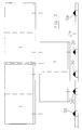
- Figure 1 shows a swap body 1 according to the invention in side view, in the supported state.
- the support legs 7 are folded down into their vertical position, and are positively secured against folding away by means of the struts 9 which extend obliquely to the transverse central plane 18.
- the fastening fittings 2, 2 ', the suspension eyes 12 for crane hooks etc. and the openings follow in the area from the bottom 8 thereof inwards and always symmetrically to the transverse center plane 18 the pockets 11 for the fork fork tines.
- FIG. 1b which shows the front end 4 of the interchangeable container with the support leg 7 folded up in the rest position, its free end even reaches close to the hanging eye 12, and in any case overlaps the closest fastening fitting 2.
- the competing space conditions between floor assembly 8, support leg 7, the suspension eyes 12 and the oblique strut 9 can be seen.
- the length of the strut 9 and its attachment point on the support leg 7 is selected such that after releasing the connection between the strut 9 and the bottom 8 of the interchangeable container 1, the strut 9 by about 130 ° to 140 ° to the support leg 7 parallel position on the inside of the support leg 7 is folded.
- the strut 7 ends with its free end in front of the nearest fastening fitting 2.
- the support legs 7 are thus in the unfolded state as close as possible to the front or rear end 4, 5 of the swap body 1, and thus result in an optimally large mutual distance in the longitudinal direction and thus a very secure support.
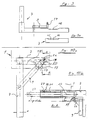
- Figure 2 shows that in this known swap body, the support legs 7 are mounted within the mounting brackets 2, 2 ', and the support legs are braced towards the front ends of the swap body as well as being folded away in the same direction for moving to the rest position .
- FIG. 3 shows a chassis adapter frame 29 of a truck, trailer or the like, which is equipped with corresponding twist locks 30 for receiving two interchangeable containers according to the invention which are arranged one behind the other.
- twistlocks 30 ' there is also an additional pair of twistlocks 30 ', of which only one can be seen in the side view in FIG. 3, which has a longitudinal distance from one of the two central pairs of twistlocks 30' such that the four twistlocks can also be a single, swap body 1 according to the invention, which results in an approximately central position in the longitudinal direction and thus an optimal weight distribution on the chassis adapter frame 29.
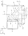
- FIG. 4a A conventional, standardized fastening fitting (EN 284) is shown in FIG. 4a in a side view from the outside of the swap body 1, and in FIG. 4b in a top view.
- the opening 31 in the bottom of the housing 32 of the fastening fitting which is important for the function and is not rotationally symmetrical, but rather elongated, can be seen.
- a fastening cone, not shown, of a Twiatlock 30 with a somewhat smaller base area can hereby be inserted from below and locked after rotation through 90 °, the mounting bracket 2 attached to the swap body with the underlying chassis of the vehicle, to which the mounting cone is rotatably attached.
- the further opening 34 arranged in the outer wall 14 serves for the vertical rope handling of the swap body.
- the distance from the longitudinal central axis 13 of the housing to its outer surface of the outer wall 14, that is to say half its width, is at least 89 mm.
- the outer wall 14 of the fastening fitting 2 according to the invention is not designed to be continuous. Rather, an upper part 14a protrudes vertically from the bottom 8 to the inside so that the support leg 7 located in the resting position can be accommodated.
- the support leg is released in the area of the fastening fitting 2.
- the support leg release is shown in Figures 9 and 9a.
- a notch is always required when the outer edge 3 reaches relatively close to the central longitudinal plane 13 of the fastening fitting 2 and there is insufficient space for the unrestricted profile shape of the support leg 7. This is necessary, for example, when installing side walls 25 which can be folded away, as shown in FIG. 6.
- Both the web cone 23 and the fastening cone 24 are shown in their normal position and in their raised position for locking (24 ').
- the notch of the support leg 7 by a corresponding plate 16 must be designed so that it lies further outside than the entire, overhead cone 23, and to the extent that the fastening cone 24 in the raised position is not with the notch 16 or for it used, welded onto the notch collided sheet, which for this reason has bevelled outer edges 15.
- the lower area 14b of the outer wall of the fastening fitting extends close to the support leg 7, the upper edge of the lower area 14b serving as a support surface 14c.
- the fastening fitting 2 that is to say its base plate, is arranged lower in relation to the folded-up support leg 7 in FIG. 7.
- the mounting cone 24 no longer collides with the profile of the support leg 7, and the support leg 7 only has to be provided with chamfered corners 15 on its inner upper and lower longitudinal edges in order to avoid a collision with the higher track cone 23 in this area.
- the fastening fitting 2 is set sufficiently deep with its base plate in order to avoid this collision by a sufficient height spacing. Therefore, there is a vertical outer wall in the lower area 14b.
- the upper region 14 a ends in FIG. 8 above the lower edge of the support leg 7, and still above the maximum possible position of an inserted fastening cone 24 or an alternative track cone 23.
- the lower region 14b of the outer wall projects significantly further outwards from the bathing of the housing 32 of the fastening fitting 2 than the upper region 14a, and ends below the support leg 7.
- a horizontal leg as a support for the support leg, which preferably extends inwards from the lower region 14b towards the center of the housing 32, but can also have a leg, which, in contrast, points outwards in order to widen the support surface.
- This horizontal leg 14c has no direct connection with the upper region 14a, and also ends in front of the inner vertical surface of the support leg 7.
- the lower inner corner 15 of the profile of the support leg 7, directed towards the center of the housing 32, can protrude into the resulting gap, while when connecting the two upper and lower parts 14a, 14b with an equally strong material in the form of a slope, etc. a collision or rattling would already have occurred.
- the fastening fitting 2 - viewed in side view - is provided with side walls 33 which are cranked in their central region and therefore run approximately vertically at a small mutual distance in the upper region, and obliquely in the lower region strive for.
- the end edges 35 of the lower regions 14b of the outer wall are chamfered, and likewise the bottom plate 31 is provided with a chamfer 35 'in order to create the greatest possible free space for the deflecting tires of the carrier vehicle through these chamfers, each cm gained additionally being very valuable .
- the outer wall in its lower region 14b additionally has in the middle a recess 36 which points downward from the upper edge.
- the folded-up support leg 7 runs above this recess 36, so that the interior of the fastening fitting always remains accessible.
- the support leg 7 is shown in side view with a notch 16.
- the corresponding cross-sectional representation can be seen in FIG. 6.
- 9a the support leg 7 is shown with a notch only in the area of the edge 15, as can be seen in the cross-sectional view of FIG. 7.
- FIG. 11 the oblique strut 9 is shown in the strut state, and the associated latching mechanism in the vehicle longitudinal direction is viewed in FIG. 11b.
- the mandrel 17 arranged at the free end of the strut 9, which protrudes backwards from the inclined strut, must be moved with the telescopic tube 20 which can be displaced in the transverse direction of the interchangeable container 3 be locked to secure the strut 9.
- the telescopic tube 20 according to FIG. 11 is shifted to the right in the eyelet 21 until the mandrel 17 is located within the telescopic tube 20. This position is secured by a cam 27 at the inner end of the telescopic tube 20, which limits the insertion path of the telescopic tube.
- the lower edge of the eyelet 21 for the telescopic tube 20 is at the same height as the lower edge of the fastening fitting 2.
- the oblique strut 9 is made shorter than the total length of the actual strut.
- the missing difference is achieved by a hooking plate 19 which strives radially from the telescopic tube 20 and has the bore or recess for receiving the mandrel 17 at its free end.
- the eyelet 21 has at its rear end in an angular position a slot 28 for receiving a corresponding cam 27, which is in a certain rotational position on the rear end of the telescopic tube 20 projecting outwards.
- the oblique strut 9 is brought into the position provided for it, and then the telescopic tube 20 according to FIG. 10 is initially pivoted so that the hooking plate 19 pivots downwards from the dashed, approximately horizontal position , as shown in Fig. 10a.
- the pivot angle can be limited by an additional stop cam 22 on the base group 8 of the swap body.
- the telescopic tube 20 is then shifted to the right according to FIG. 10b, as a result of which the hooking plate 19 pushes over the mandrel 17 and the cam 27 of the telescopic tube 20 enters the slot 28 of the eyelet 21, whereby a bracing which is resistant to torque and bending is achieved.
- the arrangement of the telescopic tube and also the swivel angle limitation of the hooking plate 19 are chosen so that there is sufficient space for the existing carrier vehicles.
- the support legs 7 are so long that the support height 10 from the lower edge of the bottom 8 of the swap body 1 to the ground is at least 102 cm.
Landscapes
- Engineering & Computer Science (AREA)
- Mechanical Engineering (AREA)
- Transportation (AREA)
- Pallets (AREA)
- Pharmaceuticals Containing Other Organic And Inorganic Compounds (AREA)
Abstract
Description
Es sind Wechselbehälter in einigen genormten Größen bekannt, die mittels nach unten ausklappbarer Stützbeine vom LKW, Anhänger etc. abgesetzt und auch wieder aufgenommen werden können. Eine gängige Normgröße derartiger Wechselbehälter besitzt eine Länge von 7,45 m (entsprechend EN 283 und 284, grösse C 745).Swap bodies are known in some standardized sizes, which can be removed from the truck, trailer etc. by means of support legs which can be folded down and can also be picked up again. A common standard size of such swap bodies has a length of 7.45 m (according to EN 283 and 284, size C 745).
Bei diesen Wechselbehältern sind neben den Abmessungen auch die Positionen für die im Außenbereich ihres Bodens angeordneten Befestigungsbeschläge festgelegt, in welche ein vom Chassis des LKW nach oben einführbarer, nicht rotationssymmetrischer Befestigungskegel eingeführt werden kann, und nach Drehung um 90° den Wechselbehälter fest auf dem Chassis verriegelt.With these swap bodies, in addition to the dimensions, the positions for the fastening fittings arranged in the outer area of their base, into which a non-rotationally symmetrical fastening cone that can be inserted upwards from the chassis of the truck, and after swiveling through 90 °, the swap body are fixed on the chassis locked.
Die Stützbeine dieser Wechselbehälter befinden sich dabei gegenüber den Befestigungsbeschlägen - in der Seitenansicht des Wechselbehälters betrachtet - etwas zur Mitte hin versetzt.The support legs of these swap bodies are slightly offset towards the center compared to the mounting fittings - viewed in the side view of the swap body.
Die Stützbeine sind in ihrer Stützposition entlang des Außenbereiches zu den nächstliegenden Enden des Wechselbehälters hin mit einer entfernbaren Strebe gesichert und werden nach Lösen der Strebe auch in diese Richtung hochgeklappt, so daß sie in ihrer Ruheposition unter den Längsaußenkanten des Bodens des Wechselbehälters in entsprechende Haltevorrichtungen eingefahren werden können und nicht nach außen über die Breite des Wechselbehälters vorstehen. Die Sicherungs-Strebe ist verschwenkbar am Stützbein befestigt.The support legs are secured in their support position along the outer area to the nearest ends of the swap body with a removable strut and are also folded up in this direction after loosening the strut, so that they retract in their rest position under the longitudinal outer edges of the bottom of the swap body in corresponding holding devices can be and do not protrude outward beyond the width of the swap body. The securing strut is pivotally attached to the support leg.
Für die Belieferung von unterschiedlichen Verteilerdepots sowie für den Verteilerverkehr sind jedoch auch kleinere Transporteinheiten notwendig. Bekannt sind her 10-Fuß-Container sowie kleine Wechselbehälter ohne eigene, fest am Wechselbehälter befestigte Stützbeine. Diese können nur mit Fremd-Hebemitteln wie z.B. Gabelstapler oder Kran von den Trägerfahrzeugen auf- und abgesetzt werden.However, smaller transport units are also required for the supply of different distribution depots and for distribution traffic. 10-foot containers and small swap bodies without their own support legs that are firmly attached to the swap body are known. These can only be used with external lifting devices such as Forklifts or cranes can be put on and taken off the carrier vehicles.
Auch sind kleine Wechselbehälter bekannt, welche jeweils einen zusätzlichen Befestigungsbeschlag im Stützbein integriert haben. Diese Lösung hat jedoch den Nachteil, daß weitere Befestigungsbeschläge mit nicht genormten Anschlußanordnungen erforderlich sind, sowie zusätzliche Befestigungsbeschläge am Trägerfahrzeug, wenn parallel auch genormte Wechselbehälter gefahren werden sollen. Weiterhin ergeben sich dabei Toleranz- und Festigkeitsprobleme bei einer Verriegelung auf dem Trägerfahrzeug.Small interchangeable containers are also known, each of which has an additional fastening fitting integrated in the support leg. However, this solution has the disadvantage that additional fastening fittings with non-standard connection arrangements are required, as well as additional fastening fittings on the carrier vehicle if standardized swap bodies are also to be driven in parallel. Furthermore, there are tolerance and strength problems when locking on the carrier vehicle.
Andere Lösungen bestehen darin, ein Chassis für lange Norm-Wechselbehälter mit zusätzlichen Befestigungsbeschlägen so auszustatten, daß statt dessen auch zwei der halb so großen Container auf dieses Chassis gesetzt werden können.Other solutions consist of equipping a chassis for long standard swap bodies with additional fastening fittings so that two of the half-sized containers can be placed on this chassis instead.
Eine weitere Lösung besteht darin, einen Wechseladapter zu benutzen, der die Länge eines Norm-Wechselbehälters besitzt und die zum Absetzen notwendigen Stützbeine aufweist, aber ansonsten nur aus einem Rahmen bzw. einem plattenartigen Gebilde besteht, auf welches die entsprechenden kleinen Container oder Wechselbehälter aufgesetzt und verriegelt werden können.Another solution is to use an interchangeable adapter that has the length of a standard interchangeable container and has the support legs necessary for setting down, but otherwise only consists of a frame or a plate-like structure on which the corresponding small container or interchangeable container is placed and can be locked.
In der Länge gegenüber den Norm-Wechselbehältern etwa halbierte Wechselbehälter mit eigenen Stützbeinen wurden bisher nur vereinzelt verwendet, da sich dabei Platzprobleme und gegenseitige Behinderungen zwischen den Stützbeinen und den Befestigungsbeschlägen ergaben, vor allem dann, wenn die Befestigungsbeschläge dieser kleinen Wechselbehsälter zumindest im vorderen oder hinteren Bereich auf die Befestigungskegel passen sollen, die auf dem Chassis des LKW bereits für das Aufsetzen eines Norm-Wechselbehältes bzw. eines ISO-Containers vorhanden sind.The length of the swap bodies with their own support legs, which have been halved compared to the standard swap bodies, has only been used sporadically because of space problems and mutual hindrances between the support legs and the fastening fittings, especially if the fastening fittings of these small swap bodies are at least in the front or rear Area to fit on the mounting cone that is on the chassis of the truck are already available for the installation of a standard swap body or an ISO container.
Da darüber hinaus sowohl der Versatz der Befestigungsbeschläge von dem vorderen und hinteren Ende als auch von den Seitenkanten aus nach innen genormt ist und ebenso als Stützbeine in ihren Profilabmessungen standardisierte, auf das maximal zulässige Gewicht der Wechselbehälter abgestimmte, Profile verwendet werden, war damit bisher eine zufriedenstellende und dennoch ausreichend kostengünstige Lösung für kleine, quasi halblange, Wechselbehälter nicht möglich.In addition, since the offset of the fastening fittings from the front and rear ends as well as from the side edges is standardized and profiles are used as support legs in their profile dimensions, which are tailored to the maximum permissible weight of the swap bodies, this was previously one satisfactory, yet sufficiently cost-effective solution for small, quasi-half-length, swap bodies not possible.
Es ist daher die Aufgabe gemäß der vorliegenden Erfindung, einen einfachen und kostengünstigen Wechselbehälter zu schaffen, der so dimensioniert ist, daß zwei dieser Wechselbehälter hintereinander auf einem Chassis für Norm-Wechselbehälter, etwa der Länge 7,45 m, aufgesetzt, befestigt und transportiert werden können.It is therefore the object of the present invention to provide a simple and inexpensive swap body which is dimensioned such that two of these swap bodies are placed, fastened and transported one after the other on a chassis for standard swap bodies, approximately the length 7.45 m can.
Diese Aufgabe wird bei dem gattungsgemäßen Wechselbehälter durch die kennzeichnenden Merkmale des Anspruchs 1 gelöst. Vorteilhafte Ausführungsformen ergeben sich aus den Unteransprüchen.This object is achieved in the generic swap body by the characterizing features of
Dadurch, daß die Befestigungsbeschläge am Wechselbehälter bezüglich der Quermittelebene symmetrisch angeordnet sind, aber gleichzeitig gegenüber den stirnseitigen Enden des Wechselbehälters den gleichen Abstand einnehmen wie bei den genormten, großen Wechselbehältern, müssen vorhandene LKW- bzw. Anhänger-Chassis, die für Norm-Wechselbehälter bereits ausgerüstet sind, nur noch mit 2 Paar zusätzlichen, weiter zur Mitte hin liegenden Twistlocks zum Eingreifen in die entsprechenden Befestigungsbeschläge nachgerüstet werden, um zwei der erfindungsgemäßen Wechselbehälter aufnehmen zu können.Due to the fact that the mounting fittings on the swap body are arranged symmetrically with respect to the transverse center plane, but at the same time are at the same distance from the front ends of the swap body as with the standardized, large swap bodies, existing truck or trailer chassis must already be used for standard swap bodies are equipped with only 2 pairs of additional twistlocks located further towards the center for engaging in the corresponding fastening fittings in order to be able to accommodate two of the swap bodies according to the invention.
Würde man bei dieser Anordnung der Befestigungsbeschläge wie bisher üblich die Stützbeine demgegenüber nach innen, also zur Quermittelebene hin versetzt, anordnen, so wäre ihr gegenseitiger Abstand so gering, daß eine sichere Abstützung des Wechselbehälters bei ungleicher Beladung nicht mehr gegeben wäre. Es könnten auch keine Gabelstaplertaschen im mittleren Bereich angeordnet werden, da diese durch die hochgeklappten Stützbeine verdeckt würden.With this arrangement of the fastening fittings, as usual, the support legs would be offset inwards, i.e. towards the transverse median plane, arrange, their mutual distance would be so small that a secure support of the swap body would not be given with unequal loading. Forklift pockets could also not be arranged in the central area, since these would be covered by the folded-up support legs.
Daher sind die Stützbeine gegenüber den Befestigungsbeschlägen weiter gegen die stirnseitigen Enden zu angeordnet, was jedoch wieder zur Folge hat, daß das bisherige Hochklappen der Stützbeine zu den stirnseitigen Enden hin nicht mehr möglich ist, da in diesem Falle der verbleibende Abstand zwischen der Schwenkachse der Stützbeine und dem benachbarten stirnseitigen Ende des Wechselbehälters geringer ist als die Länge des Stützbeines in Stützrichtung gemessen.Therefore, the support legs relative to the mounting brackets are further arranged against the front ends, which, however, has the consequence that the previous folding of the support legs towards the front ends is no longer possible, since in this case the remaining distance between the pivot axis of the support legs and the adjacent front end of the swap body is less than the length of the support leg measured in the support direction.
Auch das Anordnen der lösbaren Sicherungsstrebe im aufgestützten Zustand wird nun vorzugsweise nach innen, also zur Quermittelebene des Wechselbehälters hin, erfolgen, da auf diese Art und Weise der größtmögliche gegenseitige Abstand der Stützbeine in Längsrichtung des Wechselbehälters zueinander erzielt werden kann.The detachable securing strut in the supported state will now also preferably be arranged inwards, that is to say to the transverse median plane of the swap body, since in this way the greatest possible mutual spacing of the support legs in the longitudinal direction of the swap body can be achieved.
Bei dieser Anordnung sind jedoch die Stützbeine in der hochgeklappten Ruheposition - besonders bei einer Erhöhung der Abstützposition, um mehr Freiheit für die Reifen des Fahrzeuges zu erhalten - so lang, daß sie mit ihren freien Enden die Befestigungsbeschläge überlappen, die ja von der Außenkante etwas nach innen zurückersetzt sind.In this arrangement, however, the support legs in the folded-up rest position - especially when the support position is increased in order to provide more freedom for the tires of the vehicle - are so long that they overlap with their free ends the mounting brackets, which are somewhat from the outer edge are replaced inside.
Bei einem normgerecht positionierten Befestigungsbeschlag, der üblicherweise aus einem im wesentlichen kubischen Gehäuse mit den notwendigen Öffnungen an der Unterseite und zu den Außenseiten des Wechselbehälters hin ausgestattet ist, verbleibt zwischen dem Gehäuse des Befestigungsbeschlages und der Außenkante des Wechselbehälters zu wenig Raum, um darin ein hochgeklapptes, übliches Stützbein mit einer Profilierung von ca. 80 x 80 mm Außenabmessungen unterzubringen.In the case of a fastening fitting positioned in accordance with the standard, which is usually equipped with an essentially cubic housing with the necessary openings on the underside and on the outside of the swap body, there is too little space between the housing of the fastening fitting and the outer edge of the swap body to allow a folded-up part to accommodate the usual support leg with a profile of approx. 80 x 80 mm outer dimensions.
Für den von unten in das Gehäuse des Befestigungsbeschlages einzuführenden und zu verdrehenden Befestigungskegel ist jedoch u. U. weniger Raum erforderlich, als es das gesamte Gehäuse des Befestigungsbeschlages beansprucht. Dies vor allem deshalb, weil der Befestigungskegel eben wegen seiner Kegelform in Längsrichtung des Containers betrachtet selbst in gesperrter Querlage von unten nach oben fortschreitend immer weniger seitlichen Raum beansprucht, wobei natürlich berücksichtigt sein muß, daß der Befestigungskegel gegenüber seiner gesperrten, auf dem Boden des Befestigungsbeschlages aufsitzenden Ruhelage vorher hochgehoben wird, und dabei mehr Raum braucht.However, for the fastening cone to be inserted and rotated from below into the housing of the fastening fitting, u. U. less space required than it takes up the entire housing of the mounting bracket. This is mainly because, because of its conical shape in the longitudinal direction of the container, the fastening cone requires less and less lateral space from bottom to top even in a locked transverse position, whereby it must of course be taken into account that the fastening cone is opposite its locked one on the bottom of the fastening fitting sitting in the rest position is lifted beforehand, and needs more space.
Diese Bahnzapfen sind grundsätzlich auf den Eisenbahnwaggons montiert. Die nach oben hin erfolgende Verdickung stellt eine Windsicherung des Containers bzw. Wechselbehälters dar. Der Bahnzapfen hat eine Bohrung für eine zusätzliche Klammersicherung, die bei diesen kleinen, hohen Wechselbehältern auch benötigt wird, da sich der kurze Wechselbehälter sonst bei Rangierstössen in Richtung der Waggonlängsachs aus seinen Zapfanlagen herauskippen kann.These trunnions are always mounted on the railway wagons. The thickening towards the top is a wind protection of the container or swap body. The trunnion has a hole for additional clip protection, which is also required for these small, high swap bodies, since the short swap body would otherwise move out in the direction of the longitudinal axis of the wagon when maneuvering can tip out his dispensing systems.
Bezüglich der Stützbein-Schrägstrebe wird angestrebt, diese möglichst weit vom Stützbein-Drehpunkt entfernt drehbar anzuordnen, um möglichst geringe spezifische Kräfte an den Lagerungen zu erhalten. Daher soll die Schrägstrebe möglichst lang sein. Im hochgeklappten Zustand des Stützbeines mit parallel dazu gelegter Schrägstrebe ist der Platz hierfür jedoch durch den Befestigungsbeschlag begrenzt.With regard to the support leg oblique strut, the aim is to arrange it rotatably as far as possible from the support leg pivot point in order to obtain the lowest possible specific forces on the bearings. Therefore, the diagonal strut should be as long as possible. When the support leg is folded up with the oblique strut parallel to it, the space for this is limited by the mounting bracket.
Weiterhin ist zu beachten, daß es noch weitere Riegelelemente, die sogenannten Bahnzapfen, gibt, die in die gleichen Befestigungsbeschläge eingeführt werden, jedoch eine andere Kontur besitzen, nämlich im unteren Bereich schlanker, im oberen Bereich ebenfalls kegelförmig nach oben hin abnehmend.It should also be noted that there are other locking elements, the so-called track pins, which are inserted into the same fastening fittings, but have a different contour, namely slimmer in the lower area and also tapering upwards in the upper area.
Die vorgeschlagene Detaillösung besteht nun darin, die Gehäuse der Befestigungsbeschläge nicht einfach kubisch zu gestalten, sondern vor allem die zur Außenseite des Wechselbehälters hin gerichtete Außenwand dieses Gehäuses abzuändern:The proposed detailed solution now consists in not simply designing the housing of the fastening fittings to be cubic, but above all that for To change the outside of the swap body facing the outer wall of this housing:
Eine Möglichkeit besteht darin, diese Außenwand von unten nach oben schräg zur Längsmittelebene des Wechselbehälters hin verlaufen zu lassen.One possibility is to have this outer wall run obliquely from bottom to top towards the longitudinal center plane of the swap body.
Eine andere Möglichkeit besteht darin, diese Seitenwand in der Längsbetrachtung gekröpft auszubilden, so daß der untere Bereich weiter außen steht als der obere Bereich, wobei beide durch ein schräges oder rechtwinkliges, ausgeklinktes vorderes und hinteres Tropfblech o. ä. miteinander verbunden sein können und der obere sowie der untere Bereich jeweils vorzugsweise lotrecht angeordnet sind.Another possibility is to make this side wall cranked in the longitudinal view, so that the lower area is further out than the upper area, both of which can be connected by an oblique or right-angled, notched front and rear drip plate or the like and the the upper and the lower area are each preferably arranged vertically.
Um auch noch die Dicke der Wandstärke der Außenwand selbst zusätzlich als Raum für das Stützbein zur Verfügung zu haben, kann auch auf eine durchgängige Ausbildung der Außenwand des Gehäuses des Befestigungsbeschlages nur im oberen, zurückspringenden Bereich oder auch ganz von oben bis unten verzichtet werden.In order to also have the thickness of the wall thickness of the outer wall itself available as space for the support leg, it is also possible to dispense with a continuous design of the outer wall of the housing of the fastening fitting only in the upper, recessed area or entirely from top to bottom.
Beispielsweise könnten ein oberer, lotrechter Teil und ein demgegenüber nach außen hin versetzter unterer, lotrechter Teil der Aussenwand ohne direkte Verbindung miteinander einerseits mit dem Boden und andererseits mit dem Deckelteil des Gehäuses verbunden sein, dazwischen jedoch eine über die gesamte Länge des Gehäuses offene Lücke klaffen.For example, an upper, vertical part and a lower, vertical part of the outer wall, which is offset towards the outside, could be connected to the floor and to the cover part of the housing without a direct connection to one another, but gap between them an open gap over the entire length of the housing .
Dadurch ist es möglich, daß das in der Ruheposition abgelegte Rechteckprofil des Stützbeines mit seinem unteren inneren, dem Befestigungsbeschlag zugewandten, Eck direkt in diese Lücke hineinragt, dabei aber noch nicht den Befestigungskegel oder den sogenannten Bahnkegel berührt, sofern ein solcher eingesetzt ist.This makes it possible for the rectangular profile of the support leg, which is placed in the rest position, to protrude directly into this gap with its lower inner corner facing the fastening fitting, but not yet touching the fastening cone or the so-called path cone, if one is used.
Eine weitere Möglichkeit besteht darin, den oberen und unteren Bereich dieser Außenwand des Gehäuses zwar direkt miteinander zu verbinden, jedoch nur mit einer äußerst geringen Materialstärke, die keinerlei Beitrag zur Stabilität dieses Gehäuses mehr bietet, sondern nur das Eindringen von Schmutz über diese zusätzliche Öffnung verhindert, wobei jedoch die Gehäuse aufgrund ihrer funktionsbedingten Öffnungen ohnehin nie gegen eindringenden Schmutz gesichert sind.Another possibility is to connect the upper and lower areas of this outer wall of the housing directly to one another, but only with an extremely low material thickness, which does not contribute to the stability of this Housing offers more, but only prevents the ingress of dirt through this additional opening, but the housings are never secured against penetrating dirt anyway due to their function-related openings.
Zur Erzielung einer großen Schrägstrebenlänge können die erfindungsgemäßen Wechselbehälter - in der Seitenansicht betrachtet - symetrisch zu ihrer Mittel-Querebene - mit Befestigungsbeschlägen ausgestattet werden, welche nach oben hin verjüngend verlaufen. Hierbei wird dem Platzbedarf des Befestigungskegels Rechnung getragen.To achieve a large oblique strut length, the swap bodies according to the invention - viewed in side view - symmetrically to their central transverse plane - can be equipped with fastening fittings which taper towards the top. The space required for the mounting cone is taken into account.
Die für den Transport derartiger Wechselbehälter ausgestatteten LKW- und Anhänger-Chassis sollten dabei vorzugsweise neben den insgesamt acht für die Aufnahme von zwei hintereinander angeordneten erfindungsgemäßen Wechselbehältern vorhandenen Twistlocks noch ein weiteres Paar von Twistlocks aufweisen, welche in Längsrichtung zu einem der beiden mittigen Paare von Twistlocks einen Abstand einhält, der dem Längsabstand der Twistlocks bei den erfindungsgemäßen, halben Wechselbehältern entspricht.The truck and trailer chassis equipped for the transport of such swap bodies should preferably have a further pair of twist locks in addition to the total of eight twist locks available for accommodating two swap bodies according to the invention, which extend in the longitudinal direction to one of the two central pairs of twist locks maintains a distance which corresponds to the longitudinal distance of the twistlocks in the half swap bodies according to the invention.
Dadurch kann beim Transport von nur einem solchen Wechselbehälter auf einem doppelt langen Chassis dieser Wechselbehälter belastungsoptimiert etwa in die Mitte der vorhandenen Ladefläche gesetzt werden.As a result, when transporting only one such swap body on a double-long chassis, this swap body can be placed in the center of the existing loading area in a load-optimized manner.
Eine Ausführungsform gemäß der Erfindung ist im Folgenden beispielhaft näher beschrieben. Es zeigen:
- Figur 1:
- Ansichten des erfindungsgemäßen Wechselbehälters,
- Figur 2:
- eine Seitenansicht eines Norm-Wechselbehälters (EN 284),
- Figur 3:
- die erfindungsgemäßen Wechselbehälter im Betrieb,
- Figur 4:
- Darstellungen eines Norm-Befestigungsbeschlages (EN 284),
- Figur 5:
- eine Detaildarstellung eines Befestigungsbeschlages in Seitenansicht des Wechselbehälters,
- Figur 6:
- einen Querschnitt durch einen Befestigungsbeschlag mit ausgeklinktem Stützbein,
- Figur 7:
- einen Querschnitt durch einen Befestigungsbeschlag mit schräg ausgeklinktem Stützbein,
- Figur 8:
- einen Querschnitt durch einen Befestigungsbeschlag mit nicht ausgeklinktem Stützbein beim Aufbau mit festen Seitenwänden,
- Figur 8a:
- eine Darstellung ähnlich Figur 8, jedoch mit tiefer angeordnetem Stützbein,
- Figur 9:
- eine Aufsicht auf ein eingeklapptes, ausgeklinktes Stützbein,
- Figur 9a:
- eine Darstellung ähnlich Figur 9, jedoch mit einem Stützbein mit Ausklinkung an den Kanten,
- Figuren 10:
- einen abgestützten Wechselbehälter mit hochliegendem, verschwenkbaren Einhakblech,
- Figuren 11:
- Darstellungen ähnlich der Figuren 10 mit tiefliegendem Einhakteil.
- Figure 1:
- Views of the swap body according to the invention,
- Figure 2:
- a side view of a standard swap body (EN 284),
- Figure 3:
- the swap bodies according to the invention in operation,
- Figure 4:
- Representations of a standard fastening fitting (EN 284),
- Figure 5:
- a detailed view of a mounting bracket in side view of the swap body,
- Figure 6:
- a cross section through a mounting bracket with notched support leg,
- Figure 7:
- a cross section through a mounting bracket with obliquely notched support leg,
- Figure 8:
- a cross section through a mounting bracket with not released support leg when building with solid side walls,
- Figure 8a:
- 8 shows a representation similar to FIG. 8, but with a lower support leg,
- Figure 9:
- a supervision of a folded, notched support leg,
- Figure 9a:
- a representation similar to Figure 9, but with a support leg with notch on the edges,
- Figures 10:
- a supported swap body with a high, swiveling hook plate,
- Figures 11:
- Representations similar to Figures 10 with a deep hooking part.
Figur 1 zeigt einen erfindungsgemäßen Wechselbehälter 1 in der Seitenansicht, im aufgestützten Zustand. Dabei sind die Stützbeine 7 in ihre senkrechte Position nach unten geklappt, und mittels der schräg zur Quer-Mittelebene 18 hin nach oben verlaufenden Streben 9 formschlüssig gegen ein Wegklappen gesichert.Figure 1 shows a
Von den vorderen bzw. hinteren Enden 4, 5 des Wechselbehälters 1 aus folgen dann im Bereich von dessen Boden 8 nach innen zu und immer symetrisch zur Quer-Mittelebene 18 die Befestigungsbeschläge 2, 2', die Einhängeösen 12 für Kranhaken etc. und die Öffnungen der Eingrifftaschen 11 für die Gabelstabler-Zinken.From the front and
Wie aus der Figur 1b ersichtlich, die das vordere Ende 4 des Wechselbehälters mit in Ruheposition hochgeklapptem Stützbein 7 zeigt, reicht dessen freies Ende sogar bis nahe an die Einhängeöse 12 heran, und überlappt auf jeden Fall den nächstliegenden Befestigungsbeschlag 2. Dabei sind die konkurrierenden Platzverhältnisse zwischen Bodengruppe 8, Stützbein 7, den Einhängeösen 12 und der Schrägstrebe 9 zu erkennen.As can be seen from FIG. 1b, which shows the
Wie ersichtlich, ist dabei die Länge der Strebe 9 und ihr Befestigungspunkt am Stützbein 7 so gewählt, daß nach Lösen der Verbindung zwischen der Strebe 9 und dem Boden 8 des Wechselbehälters 1 die Strebe 9 um ca. 130° bis 140°, zum Stützbein 7 parallele Lage auf der Innenseite des Stützbeines 7 herumgeklappt wird. Beim Hochklappen des Stützbeines endet die Strebe 7 mit ihrem freien Ende dabei noch vor dem nächstliegenden Befestigungsbeschlag 2.As can be seen, the length of the
Die Stützbeine 7 befinden sich im ausgeklappten Zustand damit so nahe wie möglich an dem vorderen bzw. hinteren Ende 4, 5 des Wechselbehälters 1, und ergeben damit einen optimal großen gegenseitigen Abstand in Längsrichtung und damit eine sehr sichere Abstützung.The
Wie demgegenüber der Figur 2 zu entnehmen, in der ein normal langer Norm-Wechselbehälter in der Seitenansicht dargestellt ist, ergibt sich dadurch ein gegenseitiger Abstand der Stützbeine in Längsrichtung, der beim erfindungsgemäßen, kaum halb so langen Wechselbehälter, annäherend gleich groß ist, wie beim doppelt so langen Norm-Wechselbehälter.As can be seen in contrast to Figure 2, in which a normal long standard swap body is shown in side view, this results in a mutual spacing of the support legs in the longitudinal direction, which is almost the same size in the swap body according to the invention, hardly half as long as in Standard swap body twice as long.
Weiterhin zeigt Figur 2, daß bei diesem bekannten Wechselbehälter die Stützbeine 7 innerhalb der Befestigungsbeschläge 2, 2' gelagert sind, und die Stützbeine sowohl zu den stirnseitigen Enden des Wechselbehälters hin verstrebt sind, als auch in die selbe Richtung zum Verlagern in die Ruheposition weggeklappt werden.Furthermore, Figure 2 shows that in this known swap body, the
Figur 3 zeigt einen Chassis-Adapterrahmen 29 eines LKWs, Anhängers oder dgl., welcher mit entsprechenden Twistlocks 30 zur Aufnahme zweier hintereinander liegender erfindungsgemäßer Wechselbehälter ausgestattet ist.FIG. 3 shows a
Wie ebenfalls dargestellt, ist jedoch darüber hinaus noch ein zusätzliches Paar von Twistlocks 30' vorhanden, von denen in der Seitenansicht in Figur 3 nur einer zu sehen ist, welches zu einem der beiden mittigen Paare von Twistlocks 30' einen solchen Längsabstand aufweist, daß auf die damit vier Twistlocks auch ein einzelner, erfindungsgemäßer Wechselbehälter 1 aufgesetzt werden kann, wodurch sich eine annähernd mittige Lage in Längsrichtung und damit eine optimale Gewichtsverteilung auf dem Chassis-Adapterrahmen 29 ergibt.As also shown, however, there is also an additional pair of twistlocks 30 ', of which only one can be seen in the side view in FIG. 3, which has a longitudinal distance from one of the two central pairs of twistlocks 30' such that the four twistlocks can also be a single,
Dabei stört das zusätzliche, unterhalb des mittig aufgesetzten Wechselbehälters 1 nun befindliche überzählige Paar von Twistlocks 30 nicht, da der Verriegelungskegel nicht in seine nach oben vorgeschobene Funktionsposition gebracht wird, sondern in der tiefliegenden, nicht kollidierenden Ruheposition verbleibt.The additional pair of
Ein herkömmlicher, genormter Befestigungsbeschlag (EN 284) ist in den Figuren 4a in der Seitenansicht von der Außenseite des Wechselbehälters 1 her dargestellt, und in Figur 4b in der Aufsicht.A conventional, standardized fastening fitting (EN 284) is shown in FIG. 4a in a side view from the outside of the
Dabei ist zunächst die für die Funktion wichtige, nicht rotationssymetrische, sondern längliche Öffnung 31 im Boden des Gehäuses 32 des Befestigungsbeschlages zu erkennen. Ein nicht dargestellter Befestigungskegel eines Twiatlocks 30 mit etwas kleinerer Grundfläche kann hierdurch von unten eingeführt werden, und verriegelt nach Drehung um 90° den am Wechselbehälter befestigten Befestigungsbeschlag 2 mit dem darunterliegenden Chassis des Fahrzeuges, an welchem der Befestigungskegel drehbar befestigt ist.First, the
Die in der Außenwand 14 angeordnete weitere Öffnung 34 dient dem vertikalen Seilumschlag des Wechselbehälters.The
Bei dieser Art des Gehäuses des Befestigungsbeschlages 2 beträgt der Abstand von der Längsmittelachse 13 des Gehäuses bis zu seiner Außenfläche der Außenwand 14, also seine halbe Breite, mindestens 89 mm.In this type of housing of the attachment fitting 2, the distance from the longitudinal
Aufgrund der vorgeschriebenen Positionierung der Längsmittelachse 13 des Befestigungsbeschlages 2 gegenüber der Außenkante 3 des Wechselbehälters 1 verbleibt bei Verwendung dieses bekannten Befestigungsbeschlages nicht mehr genug Raum zur Unterbringung eines in der Ruheposition befindlichen Stützbeines 7, welches aus Stabilitätsgründen üblicherweise ein Rechteckprofil von 80 x 80 mm aufweist und - wie in Längsrichtung betrachtet in den Figuren 1b, 6, 7, 8, 8a dargestellt - nach dem Hochschwenken waagrecht nach innen in einen dafür vorgesehenen Freiraum als Ruheposition eingeschoben werden soll.Due to the prescribed positioning of the longitudinal
Bei diesen Lösungen ist daher die Außenwand 14 des erfindungsgemäßen Befestigungsbeschlages 2 nicht durchgängig ausgebildet. Vielmehr ragt ein oberer Teil 14a soweit innenliegend lotrecht vom Boden 8 aus nach unten, daß das in der Ruhepostition befindliche Stützbein 7 Platz findet.In these solutions, therefore, the
Bei den Lösungen der Fig. 6 und 7 ist das Stützbein im Bereich des Befestigungsbeschlages 2 ausgeklinkt. Die Stützbeinausklinkung ist in den Figuren 9 und 9a ersichtlich. Eine Ausklinkung ist immer dann erforderlich, wenn die Außenkante 3 relativ dicht an die Mittellängsebene 13 des Befestigungsbeschlages 2 heranreicht, und für die uneingeschränkte Profilform des Stützbeines 7 nicht ausreichend Platz ist. Dies ist z.B. bei dem Anbau von seitlich abklappbaren Bordwänden 25 erforderlich, wie in Fig. 6 dargestellt.In the solutions of FIGS. 6 and 7, the support leg is released in the area of the
Dabei ist sowohl der Bahnkegel 23 eingezeichnet, als auch der Befestigungskegel 24 in seiner Normalposition und in seiner zum Verriegeln hochgehobenen Position (24').Both the
Die Ausklinkung des Stützbeines 7 durch eine entsprechendes Blech 16 muß so gestaltet sein, daß sie weiter außen liegt als der gesamte, obenliegende Bahnkegel 23, und soweit außen, daß auch der Befestigungskegel 24 in der hochgeschobenen Position nicht mit der Ausklinkung 16 bzw. dem dafür verwendeten, auf die Ausklinkung aufgeschweißten Blech kollidiert, welches aus diesem Grunde abgeschrägte Außenkanten 15 aufweist.The notch of the
Der untere Bereich 14b der Außenwand des Befestigungsbeschlages reicht bis nahe an das Stützbein 7 heran, wobei die Oberkante des unteren Bereiches 14b als Auflagefläche 14c dient.The lower area 14b of the outer wall of the fastening fitting extends close to the
Demgegenüber ist in Fig. 7 der Befestigungsbeschlag 2, also dessen Bodenplatte gegenüber dem hochgeklappten Stützbein 7 tiefer angeordnet.In contrast, the
Dadurch kollidiert der Befestigungskegel 24 nicht mehr mit dem Profil des Stützbeines 7, und das Stützbein 7 muß lediglich an seinen innenliegenden oberen und unteren Längskanten mit abgeschrägten Ecken 15 ausgestattet werden, um in diesem Bereich eine Kollision mit dem höheren Bahnkegel 23 zu vermeiden.As a result, the mounting
Auf diese Art und Weise ist jedoch ein geringerer Abstand zwischen der Längsmittelebene 13 des Befestigungsbeschlages 2 und der Außenkante des Stützbeines 7 möglich, was - abhängig von der Breite des Wechselbehälters - deshalb notwendig sein kann, weil der Abstand in der Breite des Wechselbehälters zwischen den Längsmittelebenen 13 zweier Wechselbehälter 2 genormt und nicht veränderbar ist.In this way, however, a smaller distance between the
Ein unverändert quadratischer Stützbeinquerschnitt von z.B. 80 mal 80 mm ist in den Figuren 8 und 8a verwendet. Dabei ist der Abstand zwischen der Außenkante 3 des Wechselbehälters und der Längsmittelebene 13 des Befestigungsbeschlages 2 ausreichend groß, um jede Kollision mit dem im Durchmesser kleinen Bahnkegel 23 zu verhindern.An unchanged square cross-section of e.g. 80 by 80 mm is used in Figures 8 and 8a. The distance between the
Bei dem in Fig. 8 jedoch nicht ausreichenden Seitenabstand für die Vermeidung jeglicher Kollision mit dem Befestigungskegel 24 wird der Befestigungsbeschlag 2 mit seiner Bodenplatte ausreichend tief gesetzt, um durch einen ausreichenden Höhenabstand diese Kollision zu vermeiden. Deshalb existiert eine senkrechtstehende Außenwand im unteren Bereich 14b.In the case of the side spacing which is not sufficient in FIG. 8 to avoid any collision with the
Im Gegensatz dazu ist der Seitenabstand bei der Lösung gemäß Fig. 8a zwischen dem einzuschiebenden Befestigungskegel 24 und dem Profil des Stützbeines 3 so groß, daß der Boden des Befestigungsbeschlages 2 unmittelbar unterhalb des hochgeklappten Stützbeines 7 verlaufen kann, und dort als waagerechter Schenkel 14c dessen Abstützung übernimmt.In contrast, the side distance in the solution according to FIG. 8a between the
Alle diese Lösungen werden von der maximal vorgegebenen Breite eines Wechselbehälters von 2,55 m gemäß Straßenverkehrsordnung sowie dem Abstand der Längsmittelebenen 13 zweier Befestigungsbeschläge 2 in der Breite des Wechselbehälters von 2,26 m bestimmt.All of these solutions are determined by the maximum predetermined width of a swap body of 2.55 m in accordance with road traffic regulations and the distance between the longitudinal center planes 13 of two
Der obere Bereich 14 a endet in Figur 8 oberhalb der Unterkante des Stützbeines 7, und noch oberhalb der maximal möglichen Lage eines eingeführten Befestigungskegels 24 oder eines alternativen Bahnkegels 23.The
Wegen der nach unten sich stark verbreiternden Kontur dieser Befestigungselemente ragt der untere Bereich 14b der Außenwand deutlich weiter außen vom Baden des Gehäuses 32 des Befestigungsbeschlages 2 aus nach oben als der obere Bereich 14a, und endet unterhalb des Stützbeines 7.Because of the downward widening contour of these fastening elements, the lower region 14b of the outer wall projects significantly further outwards from the bathing of the
Daran schließt sich ein waagrechter Schenkel als Auflage für das Stützbein an, der sich vorzugsweise vom unteren Bereich 14b aus nach innen zur Mitte des Gehäuses 32 hin erstreckt, aber auch einen demgegenüber entgegengesetzt nach außen weisenden Schenkel zur Verbreiterung der Auflagefläche aufweisen kann.This is followed by a horizontal leg as a support for the support leg, which preferably extends inwards from the lower region 14b towards the center of the
Das nach innen ragende freie Ende dieses waagrechten Schenkels 14c hat dabei keine direkte Verbindung mit dem oberen Bereich 14a, und endet auch vor der innenliegenden senkrechten Fläche des Stützbeines 7.The inwardly projecting free end of this horizontal leg 14c has no direct connection with the
Dadurch kann die untere innenliegende, gegen die Mitte des Gehäuses 32 gerichtete, Ecke 15 des Profils des Stützbeines 7 in die dadurch entstehende Lücke hineinragen, während bei Verbindung der beiden oberen und unteren Teile 14a, 14b mit einem gleichstarken Material in Form einer Schräge etc. bereits eine Kollision bzw. ein Klappern gegeben wäre.As a result, the lower
Um die Verschmutzung möglichst gering zu halten, ist es dabei noch denkbar, die beiden freien Enden des oberen und unteren Bereiches 14a, 14b über ein äußerst dünnwandiges Material miteinander zu verbinden.In order to keep the contamination as low as possible, it is also conceivable to connect the two free ends of the upper and
Zur Erreichung einer großen Schrägstrebenlänge wird entsprechend Fig. 5 der Befestigungsbeschlag 2 - in der Seitenansicht betrachtet - mit Seitenwänden 33 versehen, welche in ihrem mittleren Bereich gekröpft sind und daher im oberen Bereich etwa senkrecht im geringen gegenseitigen Abstand verlaufen, und im unteren Bereich schräg voneinander abstreben. Zusätzlich sind die Endkanten 35 der unteren Bereiche 14b der Außenwand abgeschrägt, und ebenso die Bodenplatte 31 mit einer Abschrägung 35' versehen, um durch diese Abschrägungen einen möglichst großen Freiraum für die einfedernden Reifen des Trägerfahrzeuges zu schaffen, wobei jeder zusätzlich gewonnene cm sehr wertvoll ist.In order to achieve a large oblique strut length, according to FIG. 5, the fastening fitting 2 - viewed in side view - is provided with
Die Außenwand in ihrem unteren Bereich 14b weist zusätzlich in der Mitte eine von der Oberkante nach unten weisende Ausnehmung 36 auf. Das hochgeklappte Stützbein 7 verläuft oberhalb dieser Ausnehmung 36, so daß hierdurch das innere des Befestigungsbeschlages immer zugänglich bleibt.The outer wall in its lower region 14b additionally has in the middle a
In den Figuren 9 ist das Stützbein 7 in der Seitenansicht mit einer Ausklinkung 16 dargestellt. Die entsprechende Querschnittsdarstellung ist Fig. 6 zu entnehmen. In Fig. 9a ist das Stützbein 7 dabei mit einer Ausklinkung lediglich im Bereich der Kante 15 dargestellt, wie der Querschnittsdarstellung der Fig. 7 zu entnehmen.In Figure 9, the
In den Figuren 11 ist die Schrägstrebe 9 im Verstrebungszustand dargestellt, sowie der zugehörige Einrastmechanismus in Fahrzeuglängsrichtung betrachtet in Fig. 11b.In FIG. 11, the
Nach dem Hochklappen der Schrägstrebe 9 aus der Parallellage zum Stützbein 7, wie in Fig. 11a dargestellt, muß der am freien Ende der Strebe 9 angeordnete Dorn 17, der von der Schrägstrebe nach hinten abragt, mit dem in Querrichtung des Wechselbehälters 3 verschiebbaren Teleskoprohr 20 verrastet werden, um die Strebe 9 zu sichern. Zu diesem Zweck wird das Teleskoprohr 20 gemäß Fig. 11 in der Öse 21 nach rechts verschoben, bis der Dorn 17 sich innerhalb des Teleskoprohres 20 befindet. Diese Lage wird durch einen Nocken 27 am innenliegenden Ende des Teleskoprohres 20 abgesichert, welcher der Einschubweg des Teleskoprohres begrenzt.After the
Die Öse 21 für das Teleskoprohr 20 liegt dabei mit ihrer Unterkante in gleicher Höhe mit der Unterkante des Befestigungsbeschlages 2.The lower edge of the
Demgegenüber zeigen die analogen Figuren 10a, 10b eine Lösung, bei der - siehe Fig. 1b - die Schrägstrebe 9 wegen der Begrenzung im hochgeklappten Ruhezustand durch den Befestigungsbeschlag 2 nicht so lang ausgebildet werden kann wie es für eine gute Verstrebung zwischen Stützbein 7 und dem Bodenrahmen 8 des Wechselbehälters wünschenswert wäre.In contrast, the analog Figures 10a, 10b show a solution in which - see Fig. 1b - the
Die Schrägstrebe 9 wird dabei kürzer ausgebildet, als die Gesamtlänge der eigentlichen Verstrebung ausmacht. Die fehlende Differenz wird durch ein Einhakblech 19 erreicht, welches vom Teleskoprohr 20 aus radial abstrebt, und an seinem freien Ende die Bohrung oder Ausnehmung zur Aufnahme des Dornes 17 aufweist.The
Damit eine solche Verstrebung stabil ist, muß im Verstrebungszustand die Drehung des Teleskoprohres blockiert sein. Aus diesem Grund weist die Öse 21 an ihrem hinteren Ende in einer Winkelposition einen Schlitz 28 auf für die Aufnahme eines entsprechenden Nockens 27, der sich in einer bestimmten Drehlage auf dem hinteren Ende des Teleskoprohres 20 nach außen abragend befindet.So that such a strut is stable, the rotation of the telescopic tube must be blocked in the strut state. For this reason, the
Zum Anordnen der Verstrebung wird die Schrägstrebe 9 in die dafür vorgesehene Position gebracht, und anschließend das gemäß Fig. 10 nach in der linken Position befindliche Teleskoprohr 20 zunächst verschwenkt, so daß sich das Einhakblech 19 von der gestrichelten, etwa waagerechten Position aus nach unten verschwenkt, wie in Fig. 10a dargestellt. Der Schwenkwinkel kann durch einen zusätzlichen Anschlagnocken 22 an der Bodengruppe 8 des Wechselbehälters begrenzt werden.To arrange the strut, the
Anschließend wird das Teleskoprohr 20 gemäß Fig. 10b nach rechts verschoben, wodurch sich das Einhakblech 19 über den Dorn 17 schiebt und der Nocken 27 des Teleskoprohres 20 in den Schlitz 28 der Öse 21 gelangt, wodurch eine drehmoment- und biegesteife Verstrebung erzielt wird.The
Die Anordnung des Teleskoprohres und auch die Schwenkwinkelbegrenzung des Einhakbleches 19 sind dabei so gewählt, daß ein ausreichender Freiraum für die untervorhandenen Trägerfahrzeuge gegeben ist.The arrangement of the telescopic tube and also the swivel angle limitation of the hooking
Die Stützbeine 7 sind so lang, daß die Stützhöhe 10 von der Unterkante des Bodens 8 des Wechselbehälters 1 zum Untergrund mindestens 102 cm beträgt.The
Claims (16)
dadurch gekennzeichnet, daß
characterized in that
dadurch gekennzeichnet, daß
das Stützbein (7) in der eingeklappten Ruheposition im Außenbereich in Längsrichtung den nächstliegenden Befestigungsbeschlag (2, 2') überlapptSwap body according to one of the preceding claims,
characterized in that
the support leg (7) overlaps the nearest fastening fitting (2, 2 ') in the longitudinal direction in the folded rest position in the outer region
dadurch gekennzeichnet, daß
der Abstand zwischen dem Stüzbein (7) und der senkrechten Längsmittelachse (13) des Befestigungsbeschlages (2, 2') geringer ist als die halbe Breite eines normgerechten Befestigungsbeschlages.Swap body according to claim 2,
characterized in that
the distance between the support leg (7) and the vertical longitudinal central axis (13) of the fastening fitting (2, 2 ') is less than half the width of a fastening fitting according to standards.
dadurch gekennzeichnet, daß
die der Außenseite des Bodens (8) zuweisende Außenwand (14) des Befestigungsbeschlages (2, 2') in Längsrichtung des Wechselbehälters (1) betrachtet in ihrem oberen Bereich (14a) nicht mit ihrem unteren, weiter außen angeordneten Bereich (14b) fluchtet und der obere und untere Bereich (14a, 14b) der Außenwand (14) des Befestigungsbeschlages (2, 2') wenigstens teilweise nicht miteinander verbunden sind.Swap body according to claim 1, 2 or 3,
characterized in that
the outer wall (14) of the fastening fitting (2, 2 ') facing the outside of the base (8) in the longitudinal direction of the interchangeable container (1) does not align in its upper region (14a) with its lower region (14b) which is arranged further out and the upper and lower regions (14a, 14b) of the outer wall (14) of the fastening fitting (2, 2 ') are at least partially not connected to one another.
dadurch gekennzeichnet, daß
der obere Bereich (14a) und der untere Bereich (14b) jeweils etwa lotrecht stehen und der untere Bereich (14b) bis nahe an die Unterseite des Stützbeines (7) in dessen Ruheposition heranreicht.Swap body according to claim 5,
characterized in that
the upper area (14a) and the lower area (14b) are each approximately perpendicular and the lower area (14b) reaches close to the underside of the support leg (7) in its rest position.
dadurch gekennzeichnet, daß
der untere Bereich (14b) der Außenwand (14) an seinem oberen Ende einen etwa waagerecht verlaufenden Schenkel (14c) aufweist, der als Auflagefläche für das Stützbein (7) dient.Swap body according to claim 5,
characterized in that
the lower region (14b) of the outer wall (14) has at its upper end an approximately horizontal leg (14c) which serves as a support surface for the support leg (7).
dadurch gekennzeichnet, daß
der Befestigungsbeschlag (2, 2') keine der Außenseite des Bodens (8) zuweisende, im wesentliche senkrecht stehende, Außenwand (14) aufweist.Swap body according to claim 4,
characterized in that
the fastening fitting (2, 2 ') does not have an essentially vertical outer wall (14) facing the outside of the base (8).
dadurch gekennzeichnet, daß
das Stützbein (7) wenigstens im Bereich, der in der Ruheposition den Befestigungsbeschlag (2, 2') überlappt, ein gegenüber dem oberen Bereich des Stützbeines (7) einen auf der Innenseite reduzierten Profilquerschnitt aufweist.Swap body according to one of the preceding claims,
characterized in that
the support leg (7), at least in the area that overlaps the fastening fitting (2, 2 ') in the rest position, has a reduced profile cross section on the inside compared to the upper area of the support leg (7).
dadurch gekennzeichnet, daß
die Breite des Stützbeines (7) - betrachtet im ausgeklappten Zustand in Längsrichtung des Wechselbehälters - über die gesamte Längserstreckung gegenüber dem oberen Bereich reduziert ist.Swap body according to claim 8,
characterized in that
the width of the support leg (7) - viewed in the extended state in the longitudinal direction of the swap body - is reduced over the entire longitudinal extent compared to the upper region.
dadurch gekennzeichnet, daß
das im wesentlichen rechteckige Profil des Stützbeines (7) im unteren, den Befestigungsbeschlag (2, 2') überlappenden, Bereich wenigstens an der nach innen unten, gegen den Befestigungskegel im Befestigungsbeschlag weisenden, Eck (15) abgeschrägt ist.Swap body according to claim 9,
characterized in that
the essentially rectangular profile of the support leg (7) in the lower area overlapping the fastening fitting (2, 2 '), at least at the corner (15) pointing inwards and downward, pointing towards the fastening cone in the fastening fitting.
dadurch gekennzeichnet, daß
in der Seitenansicht des Wechselbehälters der Befestigungsbeschlag wenigstens auf der der Schrägstrebe 9 zugewandten Seite eine Seitenwand (33) aufweist, die im oberen Bereich näher an der Mitte des Befestigungsbeschlages (2) liegt als im unteren Bereich.Swap body according to one of the preceding claims,
characterized in that
in the side view of the interchangeable container, the fastening fitting has a side wall (33) at least on the side facing the inclined strut 9, which is closer to the center of the fastening fitting (2) in the upper region than in the lower region.
dadurch gekennzeichnet, daß
die Seitenwand (33) im oberen Bereich senkrecht verläuft und im unteren Bereich sich schräg nach außen erstreckt und daß die schräg nach außen verlaufende Orientierung der Seitenwand (33) so tief angeordnet ist, daß darüber das freie, spitz zulaufende Ende des der Schrägstrebe (9) Platz findet und darunter der Befestigungskegel (24).Swap body according to claim 11,
characterized in that
the side wall (33) extends vertically in the upper region and extends obliquely outwards in the lower region and that the obliquely outward orientation of the side wall (33) is arranged so deep that the free, tapered end of the oblique strut (9 ) Finds space and underneath the fastening cone (24).
dadurch gekennzeichnet, daß
der untere Bereich (14b) der Außenwand 14 von der Oberkante her nach unten eine Ausnehmung (36) aufweist, die bei in der Ruheposition befindlichem, hochgeklapptem Stützbein (7) unterhalb des Stützbeines (7) einen Zugang ins Innere des Befestigungsbeschlages (2) ermöglicht.Swap body according to one of the preceding claims,
characterized in that
the lower region (14b) of the outer wall 14 has a recess (36) from the top edge, which, when the support leg (7) is in the rest position and is folded up, below the support leg (7) enables access to the interior of the fastening fitting (2) .
dadurch gekennzeichnet, daß
die Schrägstrebe (9) an ihrem freien Ende einen nach hinten, unter den Wechselbehälter hinein abragenden Dorn (17) aufweist, der durch Schieben in eine Öffnung oder Ausnehmung eines in Querrichtung des Wechselbehälters an diesem befestigten Bauteiles gesichert werden kann.Swap body according to one of the preceding claims,
characterized in that
the inclined strut (9) has at its free end a rearwardly projecting mandrel (17), which can be secured by pushing into an opening or recess of a component fastened in the transverse direction of the interchangeable container.
dadurch gekennzeichnet, daß
die Ausnehmung der Hohlraum im stirnseitigen Ende eines Teleskoprohres (20) ist, welches in einer fest mit dem Boden (8) des Wechselbehälters angeordneten Hülse (21) verschiebbar ist.Swap body according to claim 14,
characterized in that
the recess is the cavity in the front end of a telescopic tube (20) which is displaceable in a sleeve (21) which is fixed to the bottom (8) of the interchangeable container.
dadurch gekennzeichnet, daß
die Ausnehmung im freien Ende eines radial vom Teleskoprohr (20) abragenden Einhakblech (19) angeordnet ist, welches drehfest mit dem Teleskoprohr (20) verbunden ist und in einer Winkelposition vom Teleskoprohr (20) ein Nocken (27) radial abragt, der in einen entsprechenden Schlitz (28) der das Telskoprohr (20) aufnehmenden Hülse (21) paßt, wenn das Einhakblech (19) über den Dorn (17) geschoben ist.Swap body according to claim 15,
characterized in that
the recess is arranged in the free end of a hooking plate (19) projecting radially from the telescopic tube (20), which is non-rotatably connected to the telescopic tube (20) and radially projects a cam (27) in an angular position from the telescopic tube (20), which protrudes into one Corresponding slot (28) of the sleeve (21) receiving the telescopic tube (20) fits when the hooking plate (19) is pushed over the mandrel (17).
Applications Claiming Priority (2)
| Application Number | Priority Date | Filing Date | Title |
|---|---|---|---|
| DE9416308U | 1994-10-10 | ||
| DE9416308U DE9416308U1 (en) | 1994-10-10 | 1994-10-10 | Swap body |
Publications (2)
| Publication Number | Publication Date |
|---|---|
| EP0706912A1 true EP0706912A1 (en) | 1996-04-17 |
| EP0706912B1 EP0706912B1 (en) | 2000-03-22 |
Family
ID=6914709
Family Applications (1)
| Application Number | Title | Priority Date | Filing Date |
|---|---|---|---|
| EP95115883A Expired - Lifetime EP0706912B1 (en) | 1994-10-10 | 1995-10-09 | Interchangeable container |
Country Status (2)
| Country | Link |
|---|---|
| EP (1) | EP0706912B1 (en) |
| DE (2) | DE9416308U1 (en) |
Cited By (2)
| Publication number | Priority date | Publication date | Assignee | Title |
|---|---|---|---|---|
| WO1998015475A1 (en) | 1996-10-07 | 1998-04-16 | I.M.C.G. S.A.R.L | Container for the combined rail-and-road transport of goods, with retractable props |
| WO2000043303A1 (en) * | 1999-01-22 | 2000-07-27 | Rite-Hite Holding Corporation | Pulling-style restraint for a parked swap body |
Families Citing this family (5)
| Publication number | Priority date | Publication date | Assignee | Title |
|---|---|---|---|---|
| DE19515022C1 (en) * | 1995-04-24 | 1996-10-31 | Ackermann Fruehauf | Fastening system for fixing interchangeable containers on transport vehicles |
| DE29510075U1 (en) * | 1995-06-29 | 1996-11-07 | Krupp Fördertechnik GmbH, 47226 Duisburg | Carrier platform of a transport vehicle with clamping arrangement |
| WO1998038115A1 (en) * | 1997-02-26 | 1998-09-03 | Frank Peter Schmidt | Supporting device for containers or the like |
| US8006811B2 (en) | 2007-09-07 | 2011-08-30 | Rite-Hite Holding Corporation | Loading dock wheel restraint comprising a flexible elongate member |
| US7914042B2 (en) | 2008-05-13 | 2011-03-29 | Rite-Hite Holding Corporation | Support frame vehicle restraints |
Citations (7)
| Publication number | Priority date | Publication date | Assignee | Title |
|---|---|---|---|---|
| GB820391A (en) * | 1956-07-19 | 1959-09-16 | Jean Ernest Fernand Lion | Improved container for the transportation of various goods |
| DE2003495A1 (en) * | 1970-01-27 | 1971-08-19 | Ackermann Fahrzeugbau | Truck with changeable superstructure provided with supports |
| CH579470A5 (en) * | 1974-04-30 | 1976-09-15 | Buessing & Sohn H | |
| EP0443456A1 (en) * | 1990-02-17 | 1991-08-28 | Gerd Schulz | Support |
| DE9319064U1 (en) * | 1993-12-13 | 1994-02-10 | Babelsberger Fahrzeugtechnik GmbH, 14482 Potsdam | Support leg for swap bodies |
| EP0585198A1 (en) * | 1992-08-18 | 1994-03-02 | Alusuisse-Lonza Services Ag | Support leg for containers |
| DE9412884U1 (en) * | 1994-08-10 | 1994-10-06 | Gebr. Hellmann GmbH & Co. KG, 49090 Osnabrück | Vehicle with a chassis to accommodate swap bodies and containers for this |
-
1994
- 1994-10-10 DE DE9416308U patent/DE9416308U1/en not_active Expired - Lifetime
-
1995
- 1995-10-09 DE DE59508038T patent/DE59508038D1/en not_active Expired - Lifetime
- 1995-10-09 EP EP95115883A patent/EP0706912B1/en not_active Expired - Lifetime
Patent Citations (7)
| Publication number | Priority date | Publication date | Assignee | Title |
|---|---|---|---|---|
| GB820391A (en) * | 1956-07-19 | 1959-09-16 | Jean Ernest Fernand Lion | Improved container for the transportation of various goods |
| DE2003495A1 (en) * | 1970-01-27 | 1971-08-19 | Ackermann Fahrzeugbau | Truck with changeable superstructure provided with supports |
| CH579470A5 (en) * | 1974-04-30 | 1976-09-15 | Buessing & Sohn H | |
| EP0443456A1 (en) * | 1990-02-17 | 1991-08-28 | Gerd Schulz | Support |
| EP0585198A1 (en) * | 1992-08-18 | 1994-03-02 | Alusuisse-Lonza Services Ag | Support leg for containers |
| DE9319064U1 (en) * | 1993-12-13 | 1994-02-10 | Babelsberger Fahrzeugtechnik GmbH, 14482 Potsdam | Support leg for swap bodies |
| DE9412884U1 (en) * | 1994-08-10 | 1994-10-06 | Gebr. Hellmann GmbH & Co. KG, 49090 Osnabrück | Vehicle with a chassis to accommodate swap bodies and containers for this |
Cited By (3)
| Publication number | Priority date | Publication date | Assignee | Title |
|---|---|---|---|---|
| WO1998015475A1 (en) | 1996-10-07 | 1998-04-16 | I.M.C.G. S.A.R.L | Container for the combined rail-and-road transport of goods, with retractable props |
| WO2000043303A1 (en) * | 1999-01-22 | 2000-07-27 | Rite-Hite Holding Corporation | Pulling-style restraint for a parked swap body |
| US6318947B1 (en) | 1999-01-22 | 2001-11-20 | Rite-Hite Holding Corporation | Pulling-style restraint for a parked swap body |
Also Published As
| Publication number | Publication date |
|---|---|
| DE9416308U1 (en) | 1995-01-26 |
| DE59508038D1 (en) | 2000-04-27 |
| EP0706912B1 (en) | 2000-03-22 |
Similar Documents
| Publication | Publication Date | Title |
|---|---|---|
| DE2731386C2 (en) | ||
| WO1995023720A1 (en) | Drivable cleaning vehicle with trailer | |
| EP2090462B1 (en) | Container chassis with adjustable length | |
| EP2698296B1 (en) | Length-adjustable telescopic tube | |
| DE69508799T2 (en) | BALLAST SYSTEM FOR COMPRESSION EQUIPMENT | |
| EP0706912B1 (en) | Interchangeable container | |
| EP3666591A1 (en) | Container lock, front extension of a chassis with such a container lock and locking arrangement | |
| EP0477573A1 (en) | Tank container | |
| DE29801555U1 (en) | Structure for a transport vehicle | |
| DE19848012A1 (en) | Industrial container for transport and storage of refuse has fork lift pick-up pockets and retractable castors for use in conjunction with different systems | |
| DE8807264U1 (en) | Tank container | |
| DE102015113283A1 (en) | Construction kit for creating various removable frames for commercial vehicles as well as removable frames produced therefrom | |
| DE102020123821B3 (en) | Ballast device and mobile crane with such | |
| DE4117631A1 (en) | Adjustable length support leg for goods vehicle trailer - uses telescopic construction with spring bolt lock | |
| DE8609480U1 (en) | Device for carrying a forklift truck by truck | |
| DE20211194U1 (en) | Universal lock for containers on a trailer | |
| EP1300285A1 (en) | Arrangement for locking of different types of containers on a chassis | |
| DE69120987T2 (en) | Door lock for containers | |
| DE19859856C2 (en) | Lifting and driving unit | |
| EP0857667B1 (en) | Interchangeable silo | |
| WO2001083355A1 (en) | Cantilever lifting device for locking and unlocking containers, especially of a plurality of containers stacked one on top of the other, and corresponding method | |
| DE9316693U1 (en) | Swap body | |
| DE19515022C1 (en) | Fastening system for fixing interchangeable containers on transport vehicles | |
| DE102022113213A1 (en) | Vehicle trailer | |
| EP4056421A1 (en) | Device, system and method for securing interchangeable structures of different designs on a support frame of a vehicle trailer |
Legal Events
| Date | Code | Title | Description |
|---|---|---|---|
| PUAI | Public reference made under article 153(3) epc to a published international application that has entered the european phase |
Free format text: ORIGINAL CODE: 0009012 |
|
| AK | Designated contracting states |
Kind code of ref document: A1 Designated state(s): DE FR GB IT NL |
|
| 17P | Request for examination filed |
Effective date: 19960619 |
|
| RAP1 | Party data changed (applicant data changed or rights of an application transferred) |
Owner name: WIHAG NUTZFAHRZEUGTECHNIK GESELLSCHAFT MIT BESCHRA |
|
| 17Q | First examination report despatched |
Effective date: 19971104 |
|
| GRAG | Despatch of communication of intention to grant |
Free format text: ORIGINAL CODE: EPIDOS AGRA |
|
| GRAG | Despatch of communication of intention to grant |
Free format text: ORIGINAL CODE: EPIDOS AGRA |
|
| GRAH | Despatch of communication of intention to grant a patent |
Free format text: ORIGINAL CODE: EPIDOS IGRA |
|
| GRAH | Despatch of communication of intention to grant a patent |
Free format text: ORIGINAL CODE: EPIDOS IGRA |
|
| GRAA | (expected) grant |
Free format text: ORIGINAL CODE: 0009210 |
|
| AK | Designated contracting states |
Kind code of ref document: B1 Designated state(s): DE FR GB IT NL |
|
| PG25 | Lapsed in a contracting state [announced via postgrant information from national office to epo] |
Ref country code: IT Free format text: LAPSE BECAUSE OF FAILURE TO SUBMIT A TRANSLATION OF THE DESCRIPTION OR TO PAY THE FEE WITHIN THE PRESCRIBED TIME-LIMIT;WARNING: LAPSES OF ITALIAN PATENTS WITH EFFECTIVE DATE BEFORE 2007 MAY HAVE OCCURRED AT ANY TIME BEFORE 2007. THE CORRECT EFFECTIVE DATE MAY BE DIFFERENT FROM THE ONE RECORDED. Effective date: 20000322 Ref country code: GB Free format text: LAPSE BECAUSE OF FAILURE TO SUBMIT A TRANSLATION OF THE DESCRIPTION OR TO PAY THE FEE WITHIN THE PRESCRIBED TIME-LIMIT Effective date: 20000322 |
|
| REF | Corresponds to: |
Ref document number: 59508038 Country of ref document: DE Date of ref document: 20000427 |
|
| ET | Fr: translation filed | ||
| GBV | Gb: ep patent (uk) treated as always having been void in accordance with gb section 77(7)/1977 [no translation filed] |
Effective date: 20000322 |
|
| K2C3 | Correction of patent specification (complete document) published |
Effective date: 20000322 |
|
| NLR4 | Nl: receipt of corrected translation in the netherlands language at the initiative of the proprietor of the patent | ||
| PLBE | No opposition filed within time limit |
Free format text: ORIGINAL CODE: 0009261 |
|
| STAA | Information on the status of an ep patent application or granted ep patent |
Free format text: STATUS: NO OPPOSITION FILED WITHIN TIME LIMIT |
|
| 26N | No opposition filed | ||
| PGFP | Annual fee paid to national office [announced via postgrant information from national office to epo] |
Ref country code: NL Payment date: 20021017 Year of fee payment: 8 Ref country code: FR Payment date: 20021017 Year of fee payment: 8 |
|
| PG25 | Lapsed in a contracting state [announced via postgrant information from national office to epo] |
Ref country code: NL Free format text: LAPSE BECAUSE OF NON-PAYMENT OF DUE FEES Effective date: 20040501 |
|
| PG25 | Lapsed in a contracting state [announced via postgrant information from national office to epo] |
Ref country code: FR Free format text: LAPSE BECAUSE OF NON-PAYMENT OF DUE FEES Effective date: 20040630 |
|
| NLV4 | Nl: lapsed or anulled due to non-payment of the annual fee |
Effective date: 20040501 |
|
| REG | Reference to a national code |
Ref country code: FR Ref legal event code: ST |
|
| PGFP | Annual fee paid to national office [announced via postgrant information from national office to epo] |
Ref country code: DE Payment date: 20140915 Year of fee payment: 20 |
|
| REG | Reference to a national code |
Ref country code: DE Ref legal event code: R071 Ref document number: 59508038 Country of ref document: DE |