EP0706198A1 - Source d'électrons à conducteurs redondants - Google Patents
Source d'électrons à conducteurs redondants Download PDFInfo
- Publication number
- EP0706198A1 EP0706198A1 EP95115024A EP95115024A EP0706198A1 EP 0706198 A1 EP0706198 A1 EP 0706198A1 EP 95115024 A EP95115024 A EP 95115024A EP 95115024 A EP95115024 A EP 95115024A EP 0706198 A1 EP0706198 A1 EP 0706198A1
- Authority
- EP
- European Patent Office
- Prior art keywords
- conductor
- electron source
- strip
- extraction grid
- conductors
- Prior art date
- Legal status (The legal status is an assumption and is not a legal conclusion. Google has not performed a legal analysis and makes no representation as to the accuracy of the status listed.)
- Granted
Links
Images


Classifications
-
- H—ELECTRICITY
- H01—ELECTRIC ELEMENTS
- H01J—ELECTRIC DISCHARGE TUBES OR DISCHARGE LAMPS
- H01J1/00—Details of electrodes, of magnetic control means, of screens, or of the mounting or spacing thereof, common to two or more basic types of discharge tubes or lamps
- H01J1/02—Main electrodes
- H01J1/30—Cold cathodes, e.g. field-emissive cathode
-
- H—ELECTRICITY
- H01—ELECTRIC ELEMENTS
- H01J—ELECTRIC DISCHARGE TUBES OR DISCHARGE LAMPS
- H01J3/00—Details of electron-optical or ion-optical arrangements or of ion traps common to two or more basic types of discharge tubes or lamps
- H01J3/02—Electron guns
- H01J3/021—Electron guns using a field emission, photo emission, or secondary emission electron source
- H01J3/022—Electron guns using a field emission, photo emission, or secondary emission electron source with microengineered cathode, e.g. Spindt-type
-
- H—ELECTRICITY
- H01—ELECTRIC ELEMENTS
- H01J—ELECTRIC DISCHARGE TUBES OR DISCHARGE LAMPS
- H01J9/00—Apparatus or processes specially adapted for the manufacture, installation, removal, maintenance of electric discharge tubes, discharge lamps, or parts thereof; Recovery of material from discharge tubes or lamps
- H01J9/24—Manufacture or joining of vessels, leading-in conductors or bases
-
- H—ELECTRICITY
- H01—ELECTRIC ELEMENTS
- H01J—ELECTRIC DISCHARGE TUBES OR DISCHARGE LAMPS
- H01J2201/00—Electrodes common to discharge tubes
- H01J2201/30—Cold cathodes
- H01J2201/319—Circuit elements associated with the emitters by direct integration
-
- H—ELECTRICITY
- H01—ELECTRIC ELEMENTS
- H01J—ELECTRIC DISCHARGE TUBES OR DISCHARGE LAMPS
- H01J2329/00—Electron emission display panels, e.g. field emission display panels
Definitions
- the present invention relates, in general, to electron emission display devices, and more particularly, to a novel extraction grid for an electron emission source.
- FEDs Field emission devices
- FEDs are well known in the art and are commonly employed for a broad range of applications including image display devices.
- An example of a FED is given in United States Patent No. 5,142,184 issued to Robert C. Kane on August 25, 1992.
- FEDs typically employ at least two electrodes, a cathode conductor and a gate or extraction grid.
- the extraction grid and the cathode conductor are formed at right angles to facilitate utilizing row and column addressing to stimulate electron emission from emission tips or emitters.
- the cathode conductor and the extraction grid typically are electrically isolated by a dielectric layer. During the FED formation, pinholes can form in the dielectric layer and result in electrical shorts between the extraction grid and the cathode conductor.
- the cathode conductor and the extraction grid are forced to the same potential thereby preventing a column of emitters and the row from being energized.
- the shorted column of emitters can not generate an image, thus, a display device formed with such electrical shorts usually appear as a dark or continually bright line where the shorted emitters are positioned.
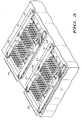
- FIG. 1 schematically illustrates an enlarged cross-sectional portion of a field emission display device 10 that has a novel electron source with redundant conductors.
- the electron source includes a novel redundant conductor scheme for an extraction grid 17 and for column conductors of the electron source.
- grid 17 has a plurality of extraction elements such as an extraction element 27 shown in FIG. 1.
- Device 10 has a substrate 11 on which other portions of device 10 are formed.
- Substrate 11 typically is an insulating or a semi-insulating material, for example, silicon having a dielectric layer or glass. In the preferred embodiment, substrate 11 is glass.
- the electron source of device 10 includes a resistive layer that generally is formed into a plurality of resistive sections on substrate 11 such as a resistive section 12 as will be seen hereinafter.
- the plurality of resistive sections typically are utilized as ballast resistors.
- the electron source also has a column conductor that includes a first column conductor strip 14 which is utilized to provide electrical contact between an emitter 13 that is formed on section 12 and an external voltage source (not shown).
- the electron source includes a second column conductor strip 25 that is not shown in FIG. 1.
- the electron source has a plurality of emitters 13 as will be seen hereinafter.
- Grid 17 is disposed on a dielectric layer 16 to electrically isolate grid 17 from substrate 11, strip 14, and section 12.
- Grid 17 has an emission opening 15 that is substantially centered to emitter 13 to permit electrons to travel from emitter 13 to a distally disposed anode 18 and form an image thereon.
- the surface of anode 18 facing emitter 13 typically is coated with a phosphor in order to provide a display as electrons strike anode 18.
- FIG. 2 schematically illustrates an enlarged plan view of a portion of extraction grid 17 shown in FIG. 1. Elements of FIG. 2 having the same reference numbers as FIG. 1 are the same.
- Device 10 (FIG. 1) has a plurality of emitters 13 as indicated in the discussion of FIG. 1. Emitters 13 are arranged in groups wherein each group is within a pixel area such as a first pixel area 28 and a second pixel area 36. The emitters within one pixel area are utilized to form a single pixel image on anode 18 (FIG. 1). Pixel areas 28 and 36 usually occur where grid 17 overlies emitters 13 and the associated column conductors such as the column conductor that includes strips 14 and 25 shown hereinafter in FIG. 3.
- Grid 17 is formed as a plurality of conductors that are electrically isolated so that a short between one conductor of grid 17 and either of strips 14 or 25 (FIG. 3) still allows the other conductor of grid 17 to function.
- grid 17 has a plurality of extraction elements within each pixel area wherein at least one extraction element generally is electrically connected to one of the plurality of conductors of grid 17.
- Each of the plurality of conductors of grid 17 may have a plurality of such extraction elements within each pixel area.
- the plurality of conductors of grid 17 includes a first conductor strip 21 that is positioned near an edge of pixel areas 28 and 36, and a substantially parallel second conductor strip 22 that is spaced a distance 29, illustrated by an arrow, from conductor strip 21.
- Distance 29 is approximately twelve to twenty-five microns in order to obtain the desired pixel density.
- Strips 21 and 22 are approximately two to one hundred microns wide in order to have a low resistance to minimize switching time, and to match the pixel size.
- Strip 22 is positioned near an edge of pixel areas 28 and 36 that is opposite of strip 21.
- grid 17 has a first extraction element 23, illustrated by a dashed box, and a second extraction element 26, also illustrated by a dashed box.
- Element 23 is formed in the portion of conductor strip 21 overlying emitters 13, and element 26 is adjacent to and substantially parallel to strip 22. Element 26 is electrically connected to strip 21 by an "L" shaped conductor extension of strip 21.
- a third extraction element 27, illustrated by a dashed box, is formed in the portion of conductor strip 22 overlying emitters 13, and a fourth extraction element 24, illustrated by a dashed box, is adjacent to and substantially parallel to strip 21 and is between strip 21 and element 26.
- Element 24 is electrically connected to strip 22 by an "L" shaped conductor extension of strip 22. Consequently, element 26 is a second distance 37 from element 23, and element 24 is a third distance 38 from element 23 such that distance 37 is less than distance 29, and distance 38 is less than distance 37.
- Elements 23, 24, 26, and 27 can have other shapes, for example, each conductor strip 21 and 22 may have only one large square projecting from each of conductor strips 21 and 22.
- Each element 23, 24, 26, and 27 has a plurality of emission openings 15 wherein each opening corresponds to an emitter of plurality of emitters 13 as indicated in the discussion of FIG. 1.
- Grid 17 also has, within pixel area 36, extraction elements 31, 32, 33, and 34 that are similar to elements 23, 24, 26, and 27, respectively. It should be noted that the portion of device 10 shown in FIG. 1 is a cross-section that cuts through element 27 so that only the portion that includes an emitter 13 that is near strip 14 is shown in the FIG. 1 cross-section.
- strip 21 or 22 is shorted to an underlying cathode conductor, then the external grid voltage (not shown) can be applied to the remaining non-shorted strip of strips 21 and 22 in order to provide an image on anode 18 (FIG. 1).
- the shorted strip of strips 21 and 22 is not utilized. The short can be determined when device 10 (FIG. 1) is tested prior to connecting all external electronics (not shown) to display 10.
- FIG. 3 schematically illustrates novel redundant cathode conductors 39 and 40 that also facilitate using device 10 when an electrical short occurs. Elements of FIG. 3 that are the same as FIG. 1 and FIG. 2 have the same reference numbers.
- Conductor 40 includes strip 14 and strip 25 that a substantially parallel and along opposite sides of area 28.
- a plurality of resistive sections 12, 19, 20, and 30 are formed on substrate 11 between strips 14 and 25 in area 28. Sections 12, 19, 20, and 30 are formed in a pattern to underlie extraction elements 27, 26, 24, and 23 (FIG. 2), respectively.
- Sections 12, 19, 20, and 30 can be formed by applying a continuous resistive layer and etching the layer as is well known to those skilled in the art.
- Strip 14 connects sections 12 and 20 into a pattern that corresponds to elements 27 and 24, respectively, while strip 25 connects sections 19 and 30 into a pattern that corresponds to elements 26 and 23, respectively.
- Emitters 13 are then formed on sections 12, 19, 20, and 30. For simplicity of the drawing, only six emitters are illustrated on each section 12, 19, 20, and 30 in FIG. 3.
- conductor 39 is within area 36 and includes a conductor strip 41 and a conductor strip 42 that corresponds to strips 14 and 25, respectively.
- Area 36 also has sections 43, 44, 46, and 47 that are similar to sections 12, 19, 20, and 30, and that correspond to the pattern of elements 34, 33, 32, and 31 (FIG. 2), respectively.
- Utilizing grid 17 (FIG. 2) together with the redundant conductor cathode conductor of FIG. 3 provides several possible usable connections if a short occurs. If strip 14 shorts to strip 21 (FIG. 2), then strip 25 and strip 22 (FIG. 2) are still usable to form an image on anode 18 (FIG. 1). Also, using the redundant cathode conductor of FIG. 3 provides an advantage over prior art cathode conductors even when the redundant cathode conductor is used with a prior art single conductor extraction grid. In such a case, the prior art extraction grid can short to one of strips 14 or 25 yet the non-shorted one of strips 14 and 25 remains available to be used for emitting electrons.
- strip 25 may not be shorted.
- strip 14 and emitters 13 on resistive sections 12 and 20 are at the same potential as the prior art extraction grid.
- strip 25 and emitters 13 on resistive sections 19 and 30 are at a different potential, thus, emitters 13 on sections 19 and 30 can emit electrons.
Applications Claiming Priority (2)
| Application Number | Priority Date | Filing Date | Title |
|---|---|---|---|
| US08/319,402 US5528098A (en) | 1994-10-06 | 1994-10-06 | Redundant conductor electron source |
| US319402 | 1994-10-06 |
Publications (2)
| Publication Number | Publication Date |
|---|---|
| EP0706198A1 true EP0706198A1 (fr) | 1996-04-10 |
| EP0706198B1 EP0706198B1 (fr) | 2000-01-19 |
Family
ID=23242110
Family Applications (1)
| Application Number | Title | Priority Date | Filing Date |
|---|---|---|---|
| EP95115024A Expired - Lifetime EP0706198B1 (fr) | 1994-10-06 | 1995-09-25 | Source d'électrons à conducteurs redondants |
Country Status (6)
| Country | Link |
|---|---|
| US (1) | US5528098A (fr) |
| EP (1) | EP0706198B1 (fr) |
| JP (1) | JPH08115677A (fr) |
| KR (1) | KR100371627B1 (fr) |
| DE (1) | DE69514606T2 (fr) |
| TW (1) | TW277137B (fr) |
Cited By (2)
| Publication number | Priority date | Publication date | Assignee | Title |
|---|---|---|---|---|
| FR2733855A1 (fr) * | 1995-05-02 | 1996-11-08 | Motorola Inc | Source d'electrons et son procede de formation |
| CN104246960A (zh) * | 2011-11-25 | 2014-12-24 | 塞莱斯Es股份有限公司 | 电子发射冷阴极器件 |
Families Citing this family (6)
| Publication number | Priority date | Publication date | Assignee | Title |
|---|---|---|---|---|
| US5633561A (en) * | 1996-03-28 | 1997-05-27 | Motorola | Conductor array for a flat panel display |
| US6297586B1 (en) | 1998-03-09 | 2001-10-02 | Kabushiki Kaisha Toshiba | Cold-cathode power switching device of field-emission type |
| KR20010003042A (ko) * | 1999-06-21 | 2001-01-15 | 김영환 | 전계 방출 표시 소자 |
| KR100400494B1 (ko) * | 2001-02-22 | 2003-10-08 | 주식회사 청구양행 | 컷트 파일 환편지 및 그 편성방법 |
| KR100455358B1 (ko) * | 2001-08-30 | 2004-11-12 | 채병기 | 슬라이버 환편지 제조장치 |
| JP2007264533A (ja) * | 2006-03-30 | 2007-10-11 | Futaba Corp | 電界放出形表示素子及びその駆動方法 |
Citations (3)
| Publication number | Priority date | Publication date | Assignee | Title |
|---|---|---|---|---|
| EP0316214A1 (fr) * | 1987-11-06 | 1989-05-17 | Commissariat A L'energie Atomique | Source d'électrons à cathodes émissives à micropointes et dispositif de visualisation par cathodoluminescence excitée par émission de champ, utilisant cette source |
| US5142184A (en) | 1990-02-09 | 1992-08-25 | Kane Robert C | Cold cathode field emission device with integral emitter ballasting |
| FR2713394A1 (fr) * | 1993-11-29 | 1995-06-09 | Futaba Denshi Kogyo Kk | Source d'électron de type à émission de champ. |
Family Cites Families (2)
| Publication number | Priority date | Publication date | Assignee | Title |
|---|---|---|---|---|
| FR2663462B1 (fr) * | 1990-06-13 | 1992-09-11 | Commissariat Energie Atomique | Source d'electrons a cathodes emissives a micropointes. |
| US5157309A (en) * | 1990-09-13 | 1992-10-20 | Motorola Inc. | Cold-cathode field emission device employing a current source means |
-
1994
- 1994-10-06 US US08/319,402 patent/US5528098A/en not_active Expired - Lifetime
-
1995
- 1995-09-15 TW TW084109657A patent/TW277137B/zh active
- 1995-09-25 EP EP95115024A patent/EP0706198B1/fr not_active Expired - Lifetime
- 1995-09-25 DE DE69514606T patent/DE69514606T2/de not_active Expired - Fee Related
- 1995-09-29 JP JP27506895A patent/JPH08115677A/ja active Pending
- 1995-10-06 KR KR1019950034205A patent/KR100371627B1/ko not_active IP Right Cessation
Patent Citations (4)
| Publication number | Priority date | Publication date | Assignee | Title |
|---|---|---|---|---|
| EP0316214A1 (fr) * | 1987-11-06 | 1989-05-17 | Commissariat A L'energie Atomique | Source d'électrons à cathodes émissives à micropointes et dispositif de visualisation par cathodoluminescence excitée par émission de champ, utilisant cette source |
| US5142184A (en) | 1990-02-09 | 1992-08-25 | Kane Robert C | Cold cathode field emission device with integral emitter ballasting |
| US5142184B1 (en) | 1990-02-09 | 1995-11-21 | Motorola Inc | Cold cathode field emission device with integral emitter ballasting |
| FR2713394A1 (fr) * | 1993-11-29 | 1995-06-09 | Futaba Denshi Kogyo Kk | Source d'électron de type à émission de champ. |
Cited By (3)
| Publication number | Priority date | Publication date | Assignee | Title |
|---|---|---|---|---|
| FR2733855A1 (fr) * | 1995-05-02 | 1996-11-08 | Motorola Inc | Source d'electrons et son procede de formation |
| CN104246960A (zh) * | 2011-11-25 | 2014-12-24 | 塞莱斯Es股份有限公司 | 电子发射冷阴极器件 |
| CN104246960B (zh) * | 2011-11-25 | 2016-11-16 | 塞莱斯Es股份有限公司 | 电子发射冷阴极器件 |
Also Published As
| Publication number | Publication date |
|---|---|
| DE69514606T2 (de) | 2000-08-31 |
| KR960015660A (ko) | 1996-05-22 |
| JPH08115677A (ja) | 1996-05-07 |
| US5528098A (en) | 1996-06-18 |
| KR100371627B1 (ko) | 2003-03-26 |
| DE69514606D1 (de) | 2000-02-24 |
| EP0706198B1 (fr) | 2000-01-19 |
| TW277137B (fr) | 1996-06-01 |
Similar Documents
| Publication | Publication Date | Title |
|---|---|---|
| US6538391B1 (en) | Image display and a manufacturing method of the same | |
| US5528099A (en) | Lateral field emitter device | |
| KR100225561B1 (ko) | 전계방출형 전자원 | |
| EP0985220B1 (fr) | Fabrication de dispositif emetteur d'electrons dote d'une electrode d'emission de type echelle | |
| US5592056A (en) | Electrical protection of an anode of a flat display screen | |
| EP0681311B1 (fr) | Emetteur a effet de champ | |
| EP0404022A2 (fr) | Dispositif d'affichage plan et procédé de fabrication de ce dispositif | |
| US20060267480A1 (en) | Display device having a thin film electron source array | |
| US5631518A (en) | Electron source having short-avoiding extraction electrode and method of making same | |
| US5528098A (en) | Redundant conductor electron source | |
| US5759078A (en) | Field emission device with close-packed microtip array | |
| EP0706197B1 (fr) | Source d'électrons | |
| US20040145299A1 (en) | Line patterned gate structure for a field emission display | |
| US5633561A (en) | Conductor array for a flat panel display | |
| JPH08329867A (ja) | フラットディスプレイスクリーンのアノード | |
| US7545088B2 (en) | Field emission device | |
| US6417627B1 (en) | Matrix-addressable display with minimum column-row overlap and maximum metal line-width | |
| US6815902B1 (en) | Field emission flat screen with modulating electrode | |
| US20070024178A1 (en) | Field emission device having insulated column lines and method of manufacture | |
| JP4220122B2 (ja) | マイクロチップ型電子ソースの製造方法 | |
| US20060202605A1 (en) | Image display device | |
| US5698933A (en) | Field emission device current control apparatus and method | |
| US6822386B2 (en) | Field emitter display assembly having resistor layer | |
| JP2939151B2 (ja) | 蛍光表示管 | |
| EP0714111A1 (fr) | Conducteur de grille d'extraction et de collimation, et procédé de focalisation d'un faisceau d'électrons |
Legal Events
| Date | Code | Title | Description |
|---|---|---|---|
| PUAI | Public reference made under article 153(3) epc to a published international application that has entered the european phase |
Free format text: ORIGINAL CODE: 0009012 |
|
| AK | Designated contracting states |
Kind code of ref document: A1 Designated state(s): DE FR GB NL |
|
| 17P | Request for examination filed |
Effective date: 19961010 |
|
| 17Q | First examination report despatched |
Effective date: 19980612 |
|
| GRAG | Despatch of communication of intention to grant |
Free format text: ORIGINAL CODE: EPIDOS AGRA |
|
| GRAG | Despatch of communication of intention to grant |
Free format text: ORIGINAL CODE: EPIDOS AGRA |
|
| GRAH | Despatch of communication of intention to grant a patent |
Free format text: ORIGINAL CODE: EPIDOS IGRA |
|
| GRAH | Despatch of communication of intention to grant a patent |
Free format text: ORIGINAL CODE: EPIDOS IGRA |
|
| GRAA | (expected) grant |
Free format text: ORIGINAL CODE: 0009210 |
|
| AK | Designated contracting states |
Kind code of ref document: B1 Designated state(s): DE FR GB NL |
|
| REF | Corresponds to: |
Ref document number: 69514606 Country of ref document: DE Date of ref document: 20000224 |
|
| ET | Fr: translation filed | ||
| PGFP | Annual fee paid to national office [announced via postgrant information from national office to epo] |
Ref country code: NL Payment date: 20000620 Year of fee payment: 6 |
|
| PLBE | No opposition filed within time limit |
Free format text: ORIGINAL CODE: 0009261 |
|
| STAA | Information on the status of an ep patent application or granted ep patent |
Free format text: STATUS: NO OPPOSITION FILED WITHIN TIME LIMIT |
|
| 26N | No opposition filed | ||
| REG | Reference to a national code |
Ref country code: GB Ref legal event code: IF02 |
|
| PG25 | Lapsed in a contracting state [announced via postgrant information from national office to epo] |
Ref country code: NL Free format text: LAPSE BECAUSE OF NON-PAYMENT OF DUE FEES Effective date: 20020401 |
|
| NLV4 | Nl: lapsed or anulled due to non-payment of the annual fee |
Effective date: 20020401 |
|
| NLV4 | Nl: lapsed or anulled due to non-payment of the annual fee |
Effective date: 20020401 |
|
| PGFP | Annual fee paid to national office [announced via postgrant information from national office to epo] |
Ref country code: GB Payment date: 20050809 Year of fee payment: 11 |
|
| PGFP | Annual fee paid to national office [announced via postgrant information from national office to epo] |
Ref country code: FR Payment date: 20050902 Year of fee payment: 11 |
|
| PGFP | Annual fee paid to national office [announced via postgrant information from national office to epo] |
Ref country code: DE Payment date: 20050930 Year of fee payment: 11 |
|
| PG25 | Lapsed in a contracting state [announced via postgrant information from national office to epo] |
Ref country code: DE Free format text: LAPSE BECAUSE OF NON-PAYMENT OF DUE FEES Effective date: 20070403 |
|
| GBPC | Gb: european patent ceased through non-payment of renewal fee |
Effective date: 20060925 |
|
| REG | Reference to a national code |
Ref country code: FR Ref legal event code: ST Effective date: 20070531 |
|
| PG25 | Lapsed in a contracting state [announced via postgrant information from national office to epo] |
Ref country code: GB Free format text: LAPSE BECAUSE OF NON-PAYMENT OF DUE FEES Effective date: 20060925 |
|
| PG25 | Lapsed in a contracting state [announced via postgrant information from national office to epo] |
Ref country code: FR Free format text: LAPSE BECAUSE OF NON-PAYMENT OF DUE FEES Effective date: 20061002 |