EP0705397B1 - Aus verbundwerkstoff hergestellte bremsscheibe sowie verfahren zu deren herstellung - Google Patents
Aus verbundwerkstoff hergestellte bremsscheibe sowie verfahren zu deren herstellung Download PDFInfo
- Publication number
- EP0705397B1 EP0705397B1 EP94920807A EP94920807A EP0705397B1 EP 0705397 B1 EP0705397 B1 EP 0705397B1 EP 94920807 A EP94920807 A EP 94920807A EP 94920807 A EP94920807 A EP 94920807A EP 0705397 B1 EP0705397 B1 EP 0705397B1
- Authority
- EP
- European Patent Office
- Prior art keywords
- rotor
- brake
- brake friction
- friction plates
- insert
- Prior art date
- Legal status (The legal status is an assumption and is not a legal conclusion. Google has not performed a legal analysis and makes no representation as to the accuracy of the status listed.)
- Expired - Lifetime
Links
- 239000002131 composite material Substances 0.000 title claims abstract description 15
- 238000004519 manufacturing process Methods 0.000 title claims description 6
- 239000011156 metal matrix composite Substances 0.000 claims abstract description 20
- 238000011065 in-situ storage Methods 0.000 claims abstract description 9
- 229910045601 alloy Inorganic materials 0.000 claims abstract description 8
- 239000000956 alloy Substances 0.000 claims abstract description 8
- 238000005266 casting Methods 0.000 claims description 28
- 238000000034 method Methods 0.000 claims description 6
- 229910052782 aluminium Inorganic materials 0.000 description 18
- XAGFODPZIPBFFR-UHFFFAOYSA-N aluminium Chemical compound [Al] XAGFODPZIPBFFR-UHFFFAOYSA-N 0.000 description 18
- 229910000838 Al alloy Inorganic materials 0.000 description 12
- 238000003754 machining Methods 0.000 description 9
- 239000000463 material Substances 0.000 description 9
- 230000002787 reinforcement Effects 0.000 description 8
- 229910001060 Gray iron Inorganic materials 0.000 description 5
- 238000010276 construction Methods 0.000 description 5
- HBMJWWWQQXIZIP-UHFFFAOYSA-N silicon carbide Chemical compound [Si+]#[C-] HBMJWWWQQXIZIP-UHFFFAOYSA-N 0.000 description 5
- 229910010271 silicon carbide Inorganic materials 0.000 description 5
- 230000002093 peripheral effect Effects 0.000 description 4
- 239000000203 mixture Substances 0.000 description 3
- FYYHWMGAXLPEAU-UHFFFAOYSA-N Magnesium Chemical compound [Mg] FYYHWMGAXLPEAU-UHFFFAOYSA-N 0.000 description 2
- 229910000861 Mg alloy Inorganic materials 0.000 description 2
- 229910001069 Ti alloy Inorganic materials 0.000 description 2
- 238000004512 die casting Methods 0.000 description 2
- 238000010114 lost-foam casting Methods 0.000 description 2
- 239000011777 magnesium Substances 0.000 description 2
- 229910052751 metal Inorganic materials 0.000 description 2
- 239000002184 metal Substances 0.000 description 2
- 238000010120 permanent mold casting Methods 0.000 description 2
- 239000000843 powder Substances 0.000 description 2
- 238000007528 sand casting Methods 0.000 description 2
- 238000009716 squeeze casting Methods 0.000 description 2
- OKTJSMMVPCPJKN-UHFFFAOYSA-N Carbon Chemical compound [C] OKTJSMMVPCPJKN-UHFFFAOYSA-N 0.000 description 1
- 229910052581 Si3N4 Inorganic materials 0.000 description 1
- ATJFFYVFTNAWJD-UHFFFAOYSA-N Tin Chemical compound [Sn] ATJFFYVFTNAWJD-UHFFFAOYSA-N 0.000 description 1
- HCHKCACWOHOZIP-UHFFFAOYSA-N Zinc Chemical compound [Zn] HCHKCACWOHOZIP-UHFFFAOYSA-N 0.000 description 1
- 230000002411 adverse Effects 0.000 description 1
- 239000004411 aluminium Substances 0.000 description 1
- PNEYBMLMFCGWSK-UHFFFAOYSA-N aluminium oxide Inorganic materials [O-2].[O-2].[O-2].[Al+3].[Al+3] PNEYBMLMFCGWSK-UHFFFAOYSA-N 0.000 description 1
- 239000000919 ceramic Substances 0.000 description 1
- 230000001419 dependent effect Effects 0.000 description 1
- 239000000835 fiber Substances 0.000 description 1
- -1 for example Substances 0.000 description 1
- 239000000446 fuel Substances 0.000 description 1
- 229910002804 graphite Inorganic materials 0.000 description 1
- 239000010439 graphite Substances 0.000 description 1
- 239000011159 matrix material Substances 0.000 description 1
- 238000002844 melting Methods 0.000 description 1
- 230000008018 melting Effects 0.000 description 1
- 239000002245 particle Substances 0.000 description 1
- 230000000704 physical effect Effects 0.000 description 1
- 230000003014 reinforcing effect Effects 0.000 description 1
- 239000004576 sand Substances 0.000 description 1
- HQVNEWCFYHHQES-UHFFFAOYSA-N silicon nitride Chemical compound N12[Si]34N5[Si]62N3[Si]51N64 HQVNEWCFYHHQES-UHFFFAOYSA-N 0.000 description 1
- 239000007787 solid Substances 0.000 description 1
- 125000006850 spacer group Chemical group 0.000 description 1
- 239000013585 weight reducing agent Substances 0.000 description 1
- 229910052725 zinc Inorganic materials 0.000 description 1
- 239000011701 zinc Substances 0.000 description 1
Images

Classifications
-
- F—MECHANICAL ENGINEERING; LIGHTING; HEATING; WEAPONS; BLASTING
- F16—ENGINEERING ELEMENTS AND UNITS; GENERAL MEASURES FOR PRODUCING AND MAINTAINING EFFECTIVE FUNCTIONING OF MACHINES OR INSTALLATIONS; THERMAL INSULATION IN GENERAL
- F16D—COUPLINGS FOR TRANSMITTING ROTATION; CLUTCHES; BRAKES
- F16D65/00—Parts or details
- F16D65/02—Braking members; Mounting thereof
- F16D65/12—Discs; Drums for disc brakes
- F16D65/125—Discs; Drums for disc brakes characterised by the material used for the disc body
Definitions
- This invention relates in general to vehicle brakes and, in particular, to an improved composite disc brake rotor for use in a disc brake assembly, and to an improved casting method for producing such a rotor.
- a typical disc brake rotor is formed from grey cast iron during a sand mold casting process.
- the rotor includes a generally hat-shaped body, and an outer annular section which are integrally cast as one-piece during the casting process. This kind of rotor is commonly referred to as a "full cast” rotor.
- the hat-shaped body includes a mounting surface having a centrally locating pilot hole formed therein during casting, and a plurality of lug bolt receiving apertures equally spaced circumferentially about the pilot hole.
- the lug bolt receiving apertures are formed during a machining operation.
- the outer annular section of the rotor includes two parallel outer surfaces which define a pair of brake friction surfaces.
- the brake friction surfaces can be cast as a single solid brake friction plate, or can be cast as a pair of brake friction plates disposed in a mutually spaced apart relationship by a plurality of ribs or fins to produce a vented rotor.
- the rotor is formed with an integrally cast hub, and is referred to as a "uni-cast" rotor.
- grey cast iron rotors While grey cast iron rotors generally possess sufficient mechanical and thermal properties to satisfy requirements of disc brake systems, they are relatively heavy and, for passenger car and light truck applications, can each weigh up to approximately 30 pounds. Since rotors are considered rotating mass and unsprung mass as well as being part of the total mass of the vehicle, the weight of the rotor adversely affects the performance and fuel economy of a vehicle.
- the aluminum MMC provides the finished rotor with sufficient mechanical and thermal properties to satisfy the requirements of brake rotor designs at a significantly reduced weight. For example, it has been found that a weight reduction of approximately 60% over a comparable grey cast iron rotor can be achieved by casting the rotor from the aluminum MMC.
- U.S. Patent No. 5,183,632 to Kiuchi et al. discloses a method for producing an aluminum "composite" disc brake rotor in which only the friction plate portions are formed of a reinforced aluminum alloy, while the remainder of the rotor is an aluminum alloy.
- an aluminum alloy is first cast or press molded to form a rough-shaped disc brake rotor body.
- an annular recessed portion (corresponding to the friction plate portions) is formed in each rotor face by machining.
- a separate reinforced aluminum alloy powder preform or a mixture of an aluminum alloy powder and reinforcing particles is then placed in each of the recessed portions of the rotor.
- the rotor body including the preform or mixture is heated to a mashy state temperature, and then molded under pressure to secure the preform or mixture to the rotor body and produce a rough-shaped disc brake rotor.
- the composite rotor includes a generally annular rotor insert formed from a MMC which is cast in situ with a generally hat-shaped rotor body formed from an alloy.
- the rotor insert is formed from an aluminum based alloy containing silicon carbide particulate reinforcement, and the rotor body is formed from a conventional aluminum alloy, such as 356 aluminum.
- the rotor body includes a generally centrally located mounting surface, and a radially outwardly extending annular portion.
- the rotor insert includes a pair of brake friction plates which are disposed in mutually spaced apart relationship.
- the brake friction plates include inner surfaces and generally parallel outer surfaces.
- the outer surfaces of the brake friction plates define a pair of brake friction surfaces adapted to be frictionally engaged by a pair of brake pads of a disc brake assembly.
- at least one of the inner surfaces of the brake friction plates is provided with a plurality of spacing elements for engagement with the inner surface of the other one of the brake friction plates for maintaining the plates in a predetermined spaced apart relationship when the rotor body is cast in situ therewith.
- the method for producing the composite disc brake rotor comprises the steps of initially casting the rotor insert, placing the rotor insert in a rotor mold, and casting the hat-shaped rotor body in the rotor mold whereby the spacing elements are effective to maintain the plates in a predetermined spaced apart relationship.
- the spacing elements maintain a predetermined spacing between the outer surfaces of the plates after the rotor body is cast in situ therewith, and control tolerances to minimize machining. Additionally, the spacing elements improve the metallurgical and mechanical bonds between the rotor insert and the rotor body.
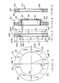
- FIG. 1 is a perspective view of a one-piece rotor insert for use in a composite disc brake rotor constructed in accordance with the present invention.
- FIG. 2 is a front view of the one-piece rotor insert.
- FIG. 3 is a cross sectional view of the one-piece rotor insert taken along lines 3-3 of FIG. 2.
- FIG. 4 is a cross sectional view of a finished composite disc brake rotor including the one-piece rotor insert of FIGS. 1 to 3.
- FIG. 5 is a perspective view showing an alternate embodiment of the rotor insert, wherein the insert is of a two-piece construction.
- FIG. 6 is a cross sectional view of the two-piece insert.
- FIG. 1 a perspective view of a rotor insert 22 for use in producing a composite disc brake rotor, indicated generally at 20 in FIG. 4, in accordance with the present invention.
- the rotor insert 22 is of a one-piece construction and includes a pair of integrally cast brake friction plates 24 and 26 which are disposed in mutually spaced apart relationship by a plurality of spacing elements 28.
- the annular rotor insert 22 is of a one-piece cast construction but for discussion purposes, can be thought of as including three distinct portions, namely, a pair of spaced apart brake friction plates 24 and 26, and a plurality of spacing elements 28. Between each pair of spacing elements 28 and the plates 24 and 26, there is formed an interspace 36. As will be discussed below, the spacing elements 28 maintain a predetermined spacing between the outer surfaces 24A and 26A of the plates 24 and 26, respectively, while a rotor body is cast in situ therewith. Additionally, the combination of the spacing elements 28 and interspaces improves the mechanical and metallurgical bonds between the rotor insert 22 and the rotor body 30.
- the brake friction plates 24 and 26 include outer annular friction surfaces 24A and 26A, respectively, which are located generally parallel to one another.
- the friction plates 24 and 26 further include outer peripheral ends 24B and 26B, respectively, which define a plate outer diameter D1, and inner peripheral ends 24C and 26C which define a plate inner diameter D2.
- Each of the spacing elements 28 includes an outer peripheral end 28B which defines an outer diameter D3, and an inner peripheral end 28C which defines an inner diameter D4.
- the outer diameter D1 of the friction plates 24 and 26 is greater than the outer diameter D3 of the spacing elements 28. Also, the inner diameter D2 of the friction plates 24 and 26 is less than the inner diameter D4 of the spacing elements 28.
- the base alloy of the MMC is an aluminum alloy, such as for example A356 aluminum, and the particulate reinforcement of the metal matrix is silicon carbide.
- the base alloy of the MMC can comprise other alloys, such as for example, magnesium or titanium alloys.
- the particulate reinforcement material can comprise other materials, such as for example, alumina, silicon nitride, graphite, ceramics, or other refractory type materials.
- the silicon carbide particulate reinforcement has a generally spheroidal to semi-spheroidal shape which allows the silicon carbide to be readily mixed with the aluminum alloy and form a mixed composite which is castable.
- the shape of the particulate reinforcement can be of other shapes, such as rods, whiskers, or fibers, to name a few.
- the volumetric content of the particulate reinforcement in the rotor insert is in the range of 10% to 30% of the total volumetric content of the composite rotor insert.
- the rotor insert 22 is trimmed to remove any risers and gates, and is placed in a rotor mold.
- the rotor insert 22 is maintained in the mold in a predetermined position by suitable means, such as for example, by the cavity of the mold itself or by projections (not shown) provided on the rotor insert 22.
- suitable means such as for example, by the cavity of the mold itself or by projections (not shown) provided on the rotor insert 22.
- the hot rotor insert 22 is removed from the mold, it is placed in the rotor mold prior to its temperature dropping below a predetermined temperature. This aids in the metallurgical bonding between the rotor insert 22 and the rotor body during the casting process.
- the particular predetermined temperature is dependent upon the physical properties of the selected aluminum MMC.
- the rotor insert 22 can be subjected to other methods to aid in the metallurgical bonding between the insert and the body.
- the rotor insert 22 can be preheated up to a predetermined temperature and/or coated with a preselected material prior to casting the rotor body in situ with the rotor insert.
- the preselected material is a metal, such as tin or zinc, having a melting temperature lower than that of the aluminum and the aluminum MMC, so that the material washes away during casting.
- a generally hat-shaped rotor body (shown at 30 in the finish machined embodiment of FIG. 4), is cast about the rotor insert 22 to form a rough-finished rotor casting (not shown).
- the casting of the rotor body 30 can be performed by any suitable casting method, such as die casting, sand casting, permanent mold casting, squeeze casting, or lost foam casting.
- the hat-shaped rotor body 30 is formed from a conventional aluminum alloy, such as for example 356 aluminum.
- a conventional aluminum alloy such as for example 356 aluminum.
- other alloys can be used, for example, magnesium or titanium alloys.
- the rotor body 30 in the embodiment shown in FIG. 4 includes a generally centrally located mounting surface 32, and a radially extending outer annular portion 34 which during casting fills the interspaces 36 defined between the brake friction plates 24 and 26 and the spacing elements 28 of the rotor insert 22 to improve the mechanical and metallurgical bonds securing the rotor insert 22 and the rotor body 30 together.
- the rough-finished rotor casting is trimmed and then finish machined to produce the finished aluminum MMC disc brake rotor 20, which is shown in FIG. 4. While not illustrated, the rough-finished rotor casting can be heat treated if so desired prior to finish machining operation.
- FIG. 4 shows the construction of the rotor after it has been finish machined.
- the finished rotor 20 is generally hat-shaped and includes the centrally located mounting surface 32, the outer annular portion 34, and the annular rotor insert 22.
- the mounting surface 32 includes a centrally located pilot hole 38 formed therein during casting and machined to final dimensions during a finish machining operation, and a plurality of lug bolt receiving apertures 40 (only one aperture 40 shown) equally spaced circumferentially about the pilot hole 38 and formed during the finish machining operation.
- the outer surfaces of the rotor including the friction surfaces 24A and 26A and the lug bolt receiving apertures 40, are finish machined to predetermined specifications. Since the spacing elements 28 maintain the predetermined distance between the outer surfaces 24A and 26A of the plates 24 and 26, respectively, only a minimal amount of the MMC material needs to be removed from the outer surfaces 24A and 26A.
- FIGS. 5 and 6 illustrate another embodiment of the rotor insert which is similar to the insert 22 of FIG. 3, except that the insert 50 comprises a pair of annular rotor inserts 52 and 54.
- the rotor inserts 52 and 54 are identical and include spacing elements 56 and 58, respectively, which are operative to space the inserts 52 and 54 apart from one another by a predetermined distance when the inserts 52 and 54 are placed in the rotor mold.
- One advantage of the present invention is that the spacing elements are operative to space the brake friction plates a predetermined distance apart from one another. As a result of this, the outer surfaces of the brake friction plates are maintained the predetermined distance apart from one another while the casting of the rotor body in situ therewith. This enables less MMC material to be used to cast the rotor insert, and thus reduces the amount of machining required during the finish machining operation.
- Another advantage of the present invention is that the spacing elements improve both the metallurgical and mechanical bonds by securing the rotor insert relative to the rotor body in both the axial and radial directions.
- the specific structure can vary.
- the shape, spacing, and number of the spacing elements 28, 56, and 58 can be varied depending upon various design considerations, such as for example, the size of the rotor.
- the rotor body has been shown and described as producing a full cast rotor, shown in FIG. 4, the rotor body can produce a rotor having an integral hub (not shown).
- one of the inserts can include more of the spacing elements than the other one, or only one of the inserts can include the spacing elements the other one not including any such elements.
- neither of the inserts can include any spacing elements formed thereon. In this case, spacers would be provided and placed in the rotor mold to space the inserts apart from one another prior to casting the rotor body in the rotor mold.
Landscapes
- Engineering & Computer Science (AREA)
- General Engineering & Computer Science (AREA)
- Mechanical Engineering (AREA)
- Braking Arrangements (AREA)
Claims (7)
- Verbundbremsscheibenrotor (20), umfassend:einen Rotorkörper (30), der aus einer Legierung gegossen ist und eine im wesentlichen mittig plazierte Anbringungsfläche (32) und einen sich radial auswärts erstreckenden Ringabschnitt (34) beinhaltet;einen im wesentlichen ringförmigen Rotoreinsatz (22), der aus einem Metallmatrixverbund gegossen ist, wobei der Rotoreinsatz (22) ein Paar Bremsscheiben (24, 26) beinhaltet, die beabstandet zueinander angeordnet sind, wobei die Scheibenbremsen (24, 26) Innenflächen und im wesentlichen parallele Außenflächen (24a, 26a) beinhalten, die ein Paar Bremsreibflächen definieren, die zum Reibschluß mit einem Paar Bremsklötze einer Scheibenbremsanordnung angepaßt sind, undzumindest eine der Innenflächen der Bremsscheiben (24, 26) ist mit einer Anzahl Abstandselemente (28) versehen zum in Anlage gelangen mit der Innenfläche der anderen Bremsscheibe (24, 26) zum Halten der Scheiben (24, 26) in einem vorbestimmten Abstand, wenn der Rotorkörper (30) hiermit in situ vergossen wird.
- Rotor nach Anspruch 1, bei dem der Rotoreinsatz (22) ein einteiliger Rotoreinsatz ist.
- Rotor nach Anspruch 1, bei dem der Rotor (22) ein zweiteiliger Rotoreinsatz ist.
- Verfahren zur Herstellung eines Verbundbremsscheibenrotors (20), umfassend die Schritte:(a) Gießen eines im wesentlichen ringförmigen Rotoreinsatzes (22) aus einem Metallmatrixverbund, wobei der Rotoreinsatz (22) ein Paar Bremsscheiben (24, 26) beinhaltet, die beabstandet zueinander angeordnet sind, wobei die Bremsscheiben (24, 26) Innenflächen und im wesentlichen parallele Außenflächen (24a, 26a) beinhalten, die ein Paar Bremsreibflächen definieren, die zum Herstellen eines Reibschlusses mit einem Paar Bremsklötze einer Scheibenbremsanordnung angepaßt sind, wobei zumindest eine der Innenflächen der Bremsscheiben (24, 26) eine Anzahl Abstandselemente (28) zum in Anlage gelangen mit der Innenfläche der anderen Bremsscheibe (24, 26) aufweist;(b) Plazieren des Rotoreinsatzes (22) in einer Rotorform und(c) Halten der Scheiben (24, 26) in vorbestimmtem Abstand und(d) Gießen eines Rotorkörpers (30) in situ hiermit.
- Verfahren nach Anspruch 4, bei dem eine Anzahl Abstandselemente (28) an zumindest einer der Innenflächen der Bremsscheiben (24, 26) zum in Anlage gelangen mit der Innenfläche der anderen Scheibe (24, 26) geschaffen sind, um die Scheiben (24, 26) in vorbestimmtem Abstand zu halten.
- Verfahren nach Anspruch 5, bei dem die Bremsscheiben (24, 26) und die Abstandselemente (28) ein einteiliges Gußstück sind.
- Bremsscheibenrotoreinsatz (22), umfassend:einen im wesentlichen ringförmigen Rotoreinsatz, der aus einem Metallmatrixverbund gegossen ist, wobei der Rotoreinsatz (22) ein Paar Bremsscheiben (24, 26) beinhaltet, die in zueinander beabstandeter Weise angeordnet sind, wobei die Bremsscheiben (24, 26) Innenflächen und im wesentlichen parallele Außenflächen (24a, 26a) beinhalten, die ein Paar Bremsreibflächen definieren, die zum Reibschluß mit einem Paar Bremsklötze einer Scheibenbremsanordnung angepaßt sind,wobei zumindest eine der Innenflächen der Bremsscheiben (24, 26) mit einer Anzahl Abstandselemente (28) zur Anlage mit der Innenfläche der anderen Bremsscheibe (24, 26) versehen ist.
Applications Claiming Priority (3)
| Application Number | Priority Date | Filing Date | Title |
|---|---|---|---|
| US8571293A | 1993-06-30 | 1993-06-30 | |
| US85712 | 1993-06-30 | ||
| PCT/US1994/007143 WO1995001519A1 (en) | 1993-06-30 | 1994-06-24 | Composite disc brake rotor and method for producing same |
Publications (2)
| Publication Number | Publication Date |
|---|---|
| EP0705397A1 EP0705397A1 (de) | 1996-04-10 |
| EP0705397B1 true EP0705397B1 (de) | 1997-12-10 |
Family
ID=22193464
Family Applications (1)
| Application Number | Title | Priority Date | Filing Date |
|---|---|---|---|
| EP94920807A Expired - Lifetime EP0705397B1 (de) | 1993-06-30 | 1994-06-24 | Aus verbundwerkstoff hergestellte bremsscheibe sowie verfahren zu deren herstellung |
Country Status (4)
| Country | Link |
|---|---|
| US (1) | US5509510A (de) |
| EP (1) | EP0705397B1 (de) |
| DE (1) | DE69407291T2 (de) |
| WO (1) | WO1995001519A1 (de) |
Families Citing this family (67)
| Publication number | Priority date | Publication date | Assignee | Title |
|---|---|---|---|---|
| IT230648Y1 (it) * | 1993-10-18 | 1999-06-09 | Brembo Spa | Disco di un freno a disco per veicoli in generale e per vetture ad elevate prestazioni in particolare |
| DE19505724A1 (de) * | 1995-02-20 | 1996-08-29 | Daimler Benz Ag | Aluminium-Bremsscheibe |
| US5626211A (en) * | 1995-10-03 | 1997-05-06 | Gewelber; Ytzhak | Multi-layer disk brake rotor |
| CA2170302C (en) * | 1996-02-26 | 2007-01-02 | Eric Siegrist | Vehicle brake |
| US5862892A (en) * | 1996-04-16 | 1999-01-26 | Hayes Lemmerz International Inc. | Composite rotor for caliper disc brakes |
| WO1997040285A1 (en) * | 1996-04-24 | 1997-10-30 | Boenaa Lars Erik | Integrated brake rotor and wheel hub |
| DE19649919C2 (de) * | 1996-12-02 | 1999-05-06 | Actech Gmbh Adv Casting Tech | Aus Verbundguß hergestellte Bremsglieder, nämlich Bremstrommel, Bremsscheibe oder dergleichen, sowie Verbundgießverfahren zur Herstellung von Bremsgliedern |
| DE19650056A1 (de) * | 1996-12-03 | 1998-06-04 | Thyssen Guss Ag | Verfahren zur Herstellung einer Bremsscheibe, insbesondere als Achs- oder Radbremsscheibe für Schienenfahrzeuge |
| US6164423A (en) * | 1997-05-02 | 2000-12-26 | Hayes Lemmerz International, Inc. | Vented rotor for caliper disc brakes and the like |
| US5927447A (en) * | 1997-06-27 | 1999-07-27 | Hayes Lemmerz International, Inc. | Composite brake drum |
| US5878843A (en) * | 1997-09-24 | 1999-03-09 | Hayes Lemmerz International, Inc. | Laminated brake rotor |
| US6243949B1 (en) * | 1998-04-10 | 2001-06-12 | Hayes Lemmerz International, Inc. | Cold forming aluminum metal matrix rotors |
| US6053290A (en) * | 1998-06-19 | 2000-04-25 | Dana Corporation | Dual web brake rotor |
| US6273440B1 (en) * | 1998-12-07 | 2001-08-14 | Reno Wilson, Inc. | Metal sports board |
| DE19859839A1 (de) * | 1998-12-23 | 2000-07-06 | Daimler Chrysler Ag | Bremseinheit |
| US6079611A (en) * | 1998-12-28 | 2000-06-27 | Shimano Inc. | Method of manufacturing ventilated brake disc |
| US6241056B1 (en) | 1998-12-29 | 2001-06-05 | Hayes Lemmerz International, Inc. | Composite brake drum |
| US6247638B1 (en) * | 1999-04-28 | 2001-06-19 | Allison Advanced Development Company | Selectively reinforced member and method of manufacture |
| DE19925003B4 (de) * | 1999-05-31 | 2004-04-29 | Dr.Ing.H.C. F. Porsche Ag | Bremsscheibe aus Faserverbund-Werkstoff |
| US6279697B1 (en) | 1999-07-30 | 2001-08-28 | Hayes Lemmerz International, Inc. | Brake rotor with non-directional braking surface |
| JP3974795B2 (ja) * | 2001-08-24 | 2007-09-12 | アイシン高丘株式会社 | ディスクロータの製造装置及び製造方法 |
| DE10339315A1 (de) * | 2003-08-27 | 2005-03-24 | Robert Bosch Gmbh | Verfahren zur Herstellung einer Bremsscheibe und Bremsscheibe |
| US7644750B2 (en) * | 2005-09-20 | 2010-01-12 | Gm Global Technology Operations, Inc. | Method of casting components with inserts for noise reduction |
| US8245758B2 (en) * | 2006-10-30 | 2012-08-21 | GM Global Technology Operations LLC | Coulomb damped disc brake rotor and method of manufacturing |
| US7937819B2 (en) * | 2005-09-19 | 2011-05-10 | GM Global Technology Operations LLC | Method of manufacturing a friction damped disc brake rotor |
| US7975750B2 (en) * | 2004-10-08 | 2011-07-12 | GM Global Technology Operations LLC | Coulomb friction damped disc brake rotors |
| US8163399B2 (en) * | 2004-10-08 | 2012-04-24 | GM Global Technology Operations LLC | Damped products and methods of making and using the same |
| US7775332B2 (en) * | 2005-09-15 | 2010-08-17 | Gm Global Technology Operations, Inc. | Bi-metal disc brake rotor and method of manufacturing |
| US20060086579A1 (en) * | 2004-10-21 | 2006-04-27 | Gerber Kraig E | Disc brake rotor |
| US7594568B2 (en) | 2005-11-30 | 2009-09-29 | Gm Global Technology Operations, Inc. | Rotor assembly and method |
| US9174274B2 (en) | 2006-05-25 | 2015-11-03 | GM Global Technology Operations LLC | Low mass multi-piece sound dampened article |
| US20090020383A1 (en) * | 2006-06-27 | 2009-01-22 | Gm Global Technology Operations, Inc. | Damped part |
| US8056233B2 (en) | 2006-06-27 | 2011-11-15 | GM Global Technology Operations LLC | Method of manufacturing an automotive component member |
| US8758902B2 (en) * | 2007-07-20 | 2014-06-24 | GM Global Technology Operations LLC | Damped product with an insert having a layer including graphite thereon and methods of making and using the same |
| US7950441B2 (en) | 2007-07-20 | 2011-05-31 | GM Global Technology Operations LLC | Method of casting damped part with insert |
| US9534651B2 (en) * | 2007-07-20 | 2017-01-03 | GM Global Technology Operations LLC | Method of manufacturing a damped part |
| US20100122880A1 (en) * | 2008-11-17 | 2010-05-20 | Gm Global Technology Operations, Inc. | Surface configurations for damping inserts |
| US9527132B2 (en) | 2007-07-20 | 2016-12-27 | GM Global Technology Operations LLC | Damped part with insert |
| US7938378B2 (en) * | 2007-08-01 | 2011-05-10 | GM Global Technology Operations LLC | Damped product with insert and method of making the same |
| US7823763B2 (en) | 2007-08-01 | 2010-11-02 | Gm Global Technology Operations, Inc. | Friction welding method and products made using the same |
| US20090035598A1 (en) * | 2007-08-03 | 2009-02-05 | Gm Global Technology Operations, Inc. | Product with metallic foam and method of manufacturing the same |
| US8118079B2 (en) * | 2007-08-17 | 2012-02-21 | GM Global Technology Operations LLC | Casting noise-damped, vented brake rotors with embedded inserts |
| US8020300B2 (en) | 2007-08-31 | 2011-09-20 | GM Global Technology Operations LLC | Cast-in-place torsion joint |
| US8210232B2 (en) | 2007-09-20 | 2012-07-03 | GM Global Technology Operations LLC | Lightweight brake rotor and components with composite materials |
| US7836938B2 (en) * | 2007-09-24 | 2010-11-23 | Gm Global Technology Operations, Inc. | Insert with tabs and damped products and methods of making the same |
| US8028739B2 (en) | 2007-10-29 | 2011-10-04 | GM Global Technology Operations LLC | Inserts with holes for damped products and methods of making and using the same |
| US8091609B2 (en) * | 2008-01-04 | 2012-01-10 | GM Global Technology Operations LLC | Method of forming casting with frictional damping insert |
| US20090260931A1 (en) * | 2008-04-18 | 2009-10-22 | Gm Global Technology Operations, Inc. | Filler material to dampen vibrating components |
| US8960382B2 (en) | 2008-04-18 | 2015-02-24 | GM Global Technology Operations LLC | Chamber with filler material to dampen vibrating components |
| US8104162B2 (en) | 2008-04-18 | 2012-01-31 | GM Global Technology Operations LLC | Insert with filler to dampen vibrating components |
| US9163682B2 (en) * | 2008-07-24 | 2015-10-20 | GM Global Technology Operations LLC | Friction damped brake drum |
| US9500242B2 (en) * | 2008-12-05 | 2016-11-22 | GM Global Technology Operations LLC | Component with inlay for damping vibrations |
| US9127734B2 (en) * | 2009-04-08 | 2015-09-08 | GM Global Technology Operations LLC | Brake rotor with intermediate portion |
| US20100276236A1 (en) * | 2009-05-01 | 2010-11-04 | Gm Global Technology Operations, Inc. | Damped product and method of making the same |
| US20100282550A1 (en) * | 2009-05-07 | 2010-11-11 | Gm Global Technology Operations, Inc. | Mode altering insert for vibration reduction in components |
| US20100294063A1 (en) * | 2009-05-22 | 2010-11-25 | Gm Global Technology Operations, Inc. | Friction damped gears |
| US8408369B2 (en) * | 2009-09-08 | 2013-04-02 | GM Global Technology Operations LLC | Bimetallic brake rotor |
| US8714232B2 (en) | 2010-09-20 | 2014-05-06 | GM Global Technology Operations LLC | Method of making a brake component |
| DE102011101126B3 (de) * | 2011-05-11 | 2012-10-18 | Audi Ag | Verfahren zum Herstellen einer Verbundguss-Bremsscheibe |
| EP3022457A4 (de) | 2013-07-19 | 2017-04-26 | Hendrickson USA, L.L.C. | Verbesserter bremsscheibenrotor für schwerlastfahrzeuge |
| TWI558930B (zh) * | 2014-11-28 | 2016-11-21 | Metal Ind Res & Dev Ct | And a method for producing a laminated product having a composite structure |
| USD784221S1 (en) * | 2015-03-24 | 2017-04-18 | Shandong Haoxin Machinery Co., Ltd. | Brake drum |
| US10253833B2 (en) | 2017-06-30 | 2019-04-09 | Honda Motor Co., Ltd. | High performance disc brake rotor |
| KR101994113B1 (ko) | 2017-10-11 | 2019-07-01 | 경창산업주식회사 | 벤티드 브레이크 디스크 |
| JP6946973B2 (ja) * | 2017-11-24 | 2021-10-13 | トヨタ自動車株式会社 | ブレーキディスクおよびそれの製造方法 |
| US11187290B2 (en) | 2018-12-28 | 2021-11-30 | Honda Motor Co., Ltd. | Aluminum ceramic composite brake assembly |
| DE102023108242A1 (de) * | 2023-03-30 | 2024-10-02 | Bergmann Automotive GmbH | Scheibenbremse für ein Fahrzeug, Fahrzeug und Verfahren zur Herstellung einer Scheibenbremse für ein Fahrzeug |
Family Cites Families (12)
| Publication number | Priority date | Publication date | Assignee | Title |
|---|---|---|---|---|
| FR2079895A5 (de) * | 1970-02-16 | 1971-11-12 | Merlin Gerin | |
| DE2048510A1 (de) * | 1970-10-02 | 1972-04-06 | Schmidt Gmbh Karl | Bremsscheibe fur Scheibenbremsen |
| US3724613A (en) * | 1970-10-16 | 1973-04-03 | Goodyear Tire & Rubber | Brake disc with beryllium core and carbon wear faces |
| GB2024346B (en) * | 1978-06-29 | 1982-06-09 | Automotive Prod Co Ltd | Brake discs |
| JPS62233531A (ja) * | 1986-03-31 | 1987-10-13 | Sumitomo Electric Ind Ltd | 摩擦式ブレ−キ |
| DE3612896A1 (de) * | 1986-04-17 | 1987-10-29 | Schwaebische Huettenwerke Gmbh | Bremsscheibenvorrichtung |
| DK189188D0 (da) * | 1988-04-07 | 1988-04-07 | Forenede Jernstoeberier A S De | Skrivebremseindretning til automobiler, bremseskive og bremseklods dertil samt fremgangsmaade til fremstilling af disse |
| US5184663A (en) * | 1988-06-14 | 1993-02-09 | Aisin Takaoka Co., Ltd. | Ventilated disk and process for making same |
| JP2987704B2 (ja) * | 1988-07-15 | 1999-12-06 | 財団法人鉄道総合技術研究所 | 高速鉄道車両用ブレーキディスク材 |
| GB2228053B (en) * | 1989-02-08 | 1993-04-14 | Automotive Products Plc | Brake disc |
| JPH04293705A (ja) * | 1991-03-20 | 1992-10-19 | Akebono Brake Res & Dev Center Ltd | アルミ基複合材ディスクロータの製造方法 |
| US5284230A (en) * | 1991-06-25 | 1994-02-08 | Aisin Takaoka Co., Ltd. | Ventilated disc unit for automotive brake system |
-
1994
- 1994-06-24 EP EP94920807A patent/EP0705397B1/de not_active Expired - Lifetime
- 1994-06-24 WO PCT/US1994/007143 patent/WO1995001519A1/en not_active Ceased
- 1994-06-24 DE DE69407291T patent/DE69407291T2/de not_active Expired - Fee Related
- 1994-12-14 US US08/356,031 patent/US5509510A/en not_active Expired - Fee Related
Also Published As
| Publication number | Publication date |
|---|---|
| DE69407291D1 (de) | 1998-01-22 |
| WO1995001519A1 (en) | 1995-01-12 |
| DE69407291T2 (de) | 1998-04-23 |
| US5509510A (en) | 1996-04-23 |
| EP0705397A1 (de) | 1996-04-10 |
Similar Documents
| Publication | Publication Date | Title |
|---|---|---|
| EP0705397B1 (de) | Aus verbundwerkstoff hergestellte bremsscheibe sowie verfahren zu deren herstellung | |
| US5620042A (en) | Method of casting a composite disc brake rotor | |
| US9174274B2 (en) | Low mass multi-piece sound dampened article | |
| US5862892A (en) | Composite rotor for caliper disc brakes | |
| US6241056B1 (en) | Composite brake drum | |
| US6131707A (en) | Disc brake rotor and method for producing same | |
| JP2671258B2 (ja) | ブレーキ板 | |
| US20040084260A1 (en) | Integrated brake rotor | |
| US5887684A (en) | Disk brake calliper | |
| US20110056777A1 (en) | Bimetallic Brake Rotor | |
| US20010025751A1 (en) | Method for producing brake discs formed of ceramic parts with metal hubs and brake disc produced according to the method | |
| US5433511A (en) | Cast wheel reinforced with a metal matrix composite | |
| US4266638A (en) | Composite brake drum | |
| US5433300A (en) | Brake caliper | |
| US20210364053A1 (en) | Thermal management of metal matrix composite systems | |
| EP0002581B1 (de) | Zusammengestellte Bremstrommel und Verfahren zu deren Herstellung | |
| US12565916B2 (en) | Method for making a braking band of a brake disc, method for making the brake disc, brake disc, and braking band for brake disc | |
| US6905010B2 (en) | Friction clutch assembly | |
| EP0725697B1 (de) | Teilweise verstärkter scheibenbremssattel auf aluminiumbasis | |
| WO1998050837A1 (en) | Solid finned rotor for caliper disc brakes and the like | |
| JPH0720422Y2 (ja) | ブレーキディスク | |
| JPH04110239U (ja) | 複合材製デイスクロータ | |
| JPS5913383Y2 (ja) | 複合ブレ−キデイスク | |
| JPS5913382Y2 (ja) | 複合ブレ−キデイスク | |
| JPH07280006A (ja) | アルミニウム合金系ディスクロータ |
Legal Events
| Date | Code | Title | Description |
|---|---|---|---|
| PUAI | Public reference made under article 153(3) epc to a published international application that has entered the european phase |
Free format text: ORIGINAL CODE: 0009012 |
|
| 17P | Request for examination filed |
Effective date: 19951130 |
|
| AK | Designated contracting states |
Kind code of ref document: A1 Designated state(s): DE FR GB IT NL |
|
| GRAG | Despatch of communication of intention to grant |
Free format text: ORIGINAL CODE: EPIDOS AGRA |
|
| 17Q | First examination report despatched |
Effective date: 19970124 |
|
| GRAG | Despatch of communication of intention to grant |
Free format text: ORIGINAL CODE: EPIDOS AGRA |
|
| GRAH | Despatch of communication of intention to grant a patent |
Free format text: ORIGINAL CODE: EPIDOS IGRA |
|
| GRAH | Despatch of communication of intention to grant a patent |
Free format text: ORIGINAL CODE: EPIDOS IGRA |
|
| GRAA | (expected) grant |
Free format text: ORIGINAL CODE: 0009210 |
|
| AK | Designated contracting states |
Kind code of ref document: B1 Designated state(s): DE FR GB IT NL |
|
| PG25 | Lapsed in a contracting state [announced via postgrant information from national office to epo] |
Ref country code: NL Free format text: LAPSE BECAUSE OF FAILURE TO SUBMIT A TRANSLATION OF THE DESCRIPTION OR TO PAY THE FEE WITHIN THE PRESCRIBED TIME-LIMIT Effective date: 19971210 Ref country code: IT Free format text: LAPSE BECAUSE OF FAILURE TO SUBMIT A TRANSLATION OF THE DESCRIPTION OR TO PAY THE FEE WITHIN THE PRESCRIBED TIME-LIMIT;WARNING: LAPSES OF ITALIAN PATENTS WITH EFFECTIVE DATE BEFORE 2007 MAY HAVE OCCURRED AT ANY TIME BEFORE 2007. THE CORRECT EFFECTIVE DATE MAY BE DIFFERENT FROM THE ONE RECORDED. Effective date: 19971210 |
|
| REF | Corresponds to: |
Ref document number: 69407291 Country of ref document: DE Date of ref document: 19980122 |
|
| ET | Fr: translation filed | ||
| NLV1 | Nl: lapsed or annulled due to failure to fulfill the requirements of art. 29p and 29m of the patents act | ||
| PLBE | No opposition filed within time limit |
Free format text: ORIGINAL CODE: 0009261 |
|
| STAA | Information on the status of an ep patent application or granted ep patent |
Free format text: STATUS: NO OPPOSITION FILED WITHIN TIME LIMIT |
|
| 26N | No opposition filed | ||
| PGFP | Annual fee paid to national office [announced via postgrant information from national office to epo] |
Ref country code: GB Payment date: 19990504 Year of fee payment: 6 |
|
| PGFP | Annual fee paid to national office [announced via postgrant information from national office to epo] |
Ref country code: FR Payment date: 19990602 Year of fee payment: 6 |
|
| PGFP | Annual fee paid to national office [announced via postgrant information from national office to epo] |
Ref country code: DE Payment date: 19990624 Year of fee payment: 6 |
|
| PG25 | Lapsed in a contracting state [announced via postgrant information from national office to epo] |
Ref country code: GB Free format text: LAPSE BECAUSE OF NON-PAYMENT OF DUE FEES Effective date: 20000624 |
|
| GBPC | Gb: european patent ceased through non-payment of renewal fee |
Effective date: 20000624 |
|
| PG25 | Lapsed in a contracting state [announced via postgrant information from national office to epo] |
Ref country code: FR Free format text: LAPSE BECAUSE OF NON-PAYMENT OF DUE FEES Effective date: 20010228 |
|
| REG | Reference to a national code |
Ref country code: FR Ref legal event code: ST |
|
| PG25 | Lapsed in a contracting state [announced via postgrant information from national office to epo] |
Ref country code: DE Free format text: LAPSE BECAUSE OF NON-PAYMENT OF DUE FEES Effective date: 20010403 |