EP0704012B1 - Element de support - Google Patents
Element de support Download PDFInfo
- Publication number
- EP0704012B1 EP0704012B1 EP94919932A EP94919932A EP0704012B1 EP 0704012 B1 EP0704012 B1 EP 0704012B1 EP 94919932 A EP94919932 A EP 94919932A EP 94919932 A EP94919932 A EP 94919932A EP 0704012 B1 EP0704012 B1 EP 0704012B1
- Authority
- EP
- European Patent Office
- Prior art keywords
- bearing part
- construction
- clamping
- supporting
- construction element
- Prior art date
- Legal status (The legal status is an assumption and is not a legal conclusion. Google has not performed a legal analysis and makes no representation as to the accuracy of the status listed.)
- Expired - Lifetime
Links
- 238000010276 construction Methods 0.000 claims abstract description 50
- 125000006850 spacer group Chemical group 0.000 claims abstract description 13
- 238000005452 bending Methods 0.000 claims abstract description 6
- 238000005266 casting Methods 0.000 claims description 4
- 239000002184 metal Substances 0.000 claims description 2
- 230000000694 effects Effects 0.000 description 3
- 238000000034 method Methods 0.000 description 2
- 229920005830 Polyurethane Foam Polymers 0.000 description 1
- 238000009408 flooring Methods 0.000 description 1
- 239000000463 material Substances 0.000 description 1
- 239000002245 particle Substances 0.000 description 1
- 229920003023 plastic Polymers 0.000 description 1
- 239000004033 plastic Substances 0.000 description 1
- 239000011496 polyurethane foam Substances 0.000 description 1
- 230000002787 reinforcement Effects 0.000 description 1
- 230000000284 resting effect Effects 0.000 description 1
- 230000000717 retained effect Effects 0.000 description 1
- 239000004576 sand Substances 0.000 description 1
- 239000007787 solid Substances 0.000 description 1
- 230000007704 transition Effects 0.000 description 1
Images

Classifications
-
- H—ELECTRICITY
- H02—GENERATION; CONVERSION OR DISTRIBUTION OF ELECTRIC POWER
- H02G—INSTALLATION OF ELECTRIC CABLES OR LINES, OR OF COMBINED OPTICAL AND ELECTRIC CABLES OR LINES
- H02G3/00—Installations of electric cables or lines or protective tubing therefor in or on buildings, equivalent structures or vehicles
- H02G3/26—Installations of cables, lines, or separate protective tubing therefor directly on or in walls, ceilings, or floors
- H02G3/263—Installation, e.g. suspension, of conduit channels or other supports
-
- E—FIXED CONSTRUCTIONS
- E02—HYDRAULIC ENGINEERING; FOUNDATIONS; SOIL SHIFTING
- E02D—FOUNDATIONS; EXCAVATIONS; EMBANKMENTS; UNDERGROUND OR UNDERWATER STRUCTURES
- E02D27/00—Foundations as substructures
- E02D27/32—Foundations for special purposes
-
- E—FIXED CONSTRUCTIONS
- E04—BUILDING
- E04B—GENERAL BUILDING CONSTRUCTIONS; WALLS, e.g. PARTITIONS; ROOFS; FLOORS; CEILINGS; INSULATION OR OTHER PROTECTION OF BUILDINGS
- E04B5/00—Floors; Floor construction with regard to insulation; Connections specially adapted therefor
-
- E—FIXED CONSTRUCTIONS
- E04—BUILDING
- E04B—GENERAL BUILDING CONSTRUCTIONS; WALLS, e.g. PARTITIONS; ROOFS; FLOORS; CEILINGS; INSULATION OR OTHER PROTECTION OF BUILDINGS
- E04B5/00—Floors; Floor construction with regard to insulation; Connections specially adapted therefor
- E04B5/02—Load-carrying floor structures formed substantially of prefabricated units
- E04B5/12—Load-carrying floor structures formed substantially of prefabricated units with wooden beams
-
- E—FIXED CONSTRUCTIONS
- E04—BUILDING
- E04D—ROOF COVERINGS; SKY-LIGHTS; GUTTERS; ROOF-WORKING TOOLS
- E04D11/00—Roof covering, as far as not restricted to features covered by only one of groups E04D1/00 - E04D9/00; Roof covering in ways not provided for by groups E04D1/00 - E04D9/00, e.g. built-up roofs, elevated load-supporting roof coverings
- E04D11/005—Supports for elevated load-supporting roof coverings
- E04D11/007—Height-adjustable spacers
-
- E—FIXED CONSTRUCTIONS
- E04—BUILDING
- E04F—FINISHING WORK ON BUILDINGS, e.g. STAIRS, FLOORS
- E04F15/00—Flooring
- E04F15/02—Flooring or floor layers composed of a number of similar elements
- E04F15/02044—Separate elements for fastening to an underlayer
-
- E—FIXED CONSTRUCTIONS
- E04—BUILDING
- E04F—FINISHING WORK ON BUILDINGS, e.g. STAIRS, FLOORS
- E04F21/00—Implements for finishing work on buildings
- E04F21/02—Implements for finishing work on buildings for applying plasticised masses to surfaces, e.g. plastering walls
- E04F21/04—Patterns or templates; Jointing rulers
- E04F21/05—Supports for jointing rulers
-
- E—FIXED CONSTRUCTIONS
- E04—BUILDING
- E04G—SCAFFOLDING; FORMS; SHUTTERING; BUILDING IMPLEMENTS OR AIDS, OR THEIR USE; HANDLING BUILDING MATERIALS ON THE SITE; REPAIRING, BREAKING-UP OR OTHER WORK ON EXISTING BUILDINGS
- E04G21/00—Preparing, conveying, or working-up building materials or building elements in situ; Other devices or measures for constructional work
- E04G21/02—Conveying or working-up concrete or similar masses able to be heaped or cast
- E04G21/10—Devices for levelling, e.g. templates or boards
-
- E—FIXED CONSTRUCTIONS
- E04—BUILDING
- E04G—SCAFFOLDING; FORMS; SHUTTERING; BUILDING IMPLEMENTS OR AIDS, OR THEIR USE; HANDLING BUILDING MATERIALS ON THE SITE; REPAIRING, BREAKING-UP OR OTHER WORK ON EXISTING BUILDINGS
- E04G25/00—Shores or struts; Chocks
-
- F—MECHANICAL ENGINEERING; LIGHTING; HEATING; WEAPONS; BLASTING
- F16—ENGINEERING ELEMENTS AND UNITS; GENERAL MEASURES FOR PRODUCING AND MAINTAINING EFFECTIVE FUNCTIONING OF MACHINES OR INSTALLATIONS; THERMAL INSULATION IN GENERAL
- F16M—FRAMES, CASINGS OR BEDS OF ENGINES, MACHINES OR APPARATUS, NOT SPECIFIC TO ENGINES, MACHINES OR APPARATUS PROVIDED FOR ELSEWHERE; STANDS; SUPPORTS
- F16M7/00—Details of attaching or adjusting engine beds, frames, or supporting-legs on foundation or base; Attaching non-moving engine parts, e.g. cylinder blocks
-
- E—FIXED CONSTRUCTIONS
- E04—BUILDING
- E04F—FINISHING WORK ON BUILDINGS, e.g. STAIRS, FLOORS
- E04F15/00—Flooring
- E04F15/02—Flooring or floor layers composed of a number of similar elements
- E04F15/02044—Separate elements for fastening to an underlayer
- E04F2015/0205—Separate elements for fastening to an underlayer with load-supporting elongated furring elements between the flooring elements and the underlayer
- E04F2015/02055—Separate elements for fastening to an underlayer with load-supporting elongated furring elements between the flooring elements and the underlayer with additional supporting elements between furring elements and underlayer
- E04F2015/02061—Separate elements for fastening to an underlayer with load-supporting elongated furring elements between the flooring elements and the underlayer with additional supporting elements between furring elements and underlayer adjustable perpendicular to the underlayer
Definitions
- the present invention relates to a device suitable for supporting and adjusting the level of a construction on a supporting surface, said construction comprising at least one form stable construction element having a lower side and two lateral surfaces facing away from each other and being a predetermined distance f apart, with which element the device may be brought into engagement, said device comprising a bearing part with an inner section and two outer sections arranged one on each side of the inner section; a spacer on the lower side of the bearing part in each outer section, said spacers being arranged to keep the bearing part at a distance, from the supporting surface; and upwardly directed clamping members permanently arranged on the upper side of the outer sections forming a stable unit therewith, the clamping members defining a space between them that reaches down to the inner section, for the receipt of said construction element.
- Special construction elements in the form of holders, placed on the ground, are used for positioning base elements for the foundation of a building.
- a foot plate of specific height must generally be cast for each holder. This method is both time-consuming and laborious and does not always ensure an exact level of the base elements.
- An alternative method is to use inserts to achieve the correct level, but there is a risk of the holder slipping off the insert since the latter is not usually secured to the holder.
- GB-A-2 185 048 describes a flooring component which is composed of two base elements and a plate which is nailed on the top of the base elements provided with a polyurethane foam layer on their underside.
- the plate has vertical lugs defining spaces for receiving crosswise battens.
- the object of the present invention is to provide a device for supporting a construction, e.g. a holder and base element of the type described, which eliminates the problems mentioned above and can be applied quickly and simply to the construction, thereby retaining it and adjusting the construction at a desired level.
- the device according to the invention can be used to support and preferably also to adjust the level of a number of different types of constructions comprising or consisting of construction elements in the form of e.g. moulds used when casting concrete floors; joists, used when laying floors indoors to carry wooden tiles or boards; walls to be erected and aligned; levelling planks used, for instance, when levelling the surface for tiling; base elements or holders therefor, and other types of moulds or beams that must be adjusted vertically; pipes for various purposes; spacer elements used when forming roofs; and screeds for carrying equipment to be used for surface levelling when casting concrete floors and roofs.
- construction elements in the form of e.g. moulds used when casting concrete floors; joists, used when laying floors indoors to carry wooden tiles or boards; walls to be erected and aligned; levelling planks used, for instance, when levelling the surface for tiling; base elements or holders therefor, and other types of moulds or beams that
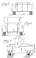
- Figure 1 is a perspective view of a device in the form of a supporting and levelling element for supporting and adjusting the level of a construction.
- Figures 2-4 are different plane views of the supporting and levelling element.
- Figure 5 is a side view of the supporting and levelling element according to Figure 1 during receipt of a construction element in the form of a beam with rectangular cross section, before the beam has loaded the supporting and levelling element.
- Figure 6 is a side view of the supporting and levelling element supporting, inter alia, the beam according to Figure 5 and illustrates the effect when the construction loads the supporting and levelling element.
- Figure 7 is a perspective view of two supporting and levelling elements supporting and loaded by a construction consisting of a lower beam and a plurality of cross-beams.
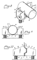
- Figures 8 and 9 are a perspective view and an end view, respectively, of the supporting and levelling element according to Figure 1, carrying a cylindrical pipe.
- Figure 10 is a side view of a supporting and levelling element according to another embodiment, for a screed of specific design.
- FIG. 1-6 of the drawings show a device according to the invention for supporting a construction 1 at a desired level above a supporting surface 13 (see particularly Figures 5 and 6).
- the device may be generally designated a supporting element, or a combined supporting and levelling element.
- Such a construction 1, acting on the device with a load Q comprises or consists of a lower rigid, i.e. form stable, construction element 2 with a bottom surface 3 for co-operation with the supporting element and two lateral surfaces 4, 5 facing away from each other, also for co-operation with the supporting element.
- the lateral surfaces 4, 5 are situated at a predetermined perpendicular distance e above the bottom surface 3 and at a predetermined distance f from each other.
- the distance f thus forms the horizontal thickness or width of the solid body 2 within at least the area of the lateral surfaces 4, 5.
- the distance e is preferably the same for both lateral surfaces 4, 5, as shown in Figure 5. It will be understood that the size and shape of the supporting and levelling element is adjusted to the particular construction element for which it is to be used.
- the construction element may have basically any cross-sectional shape whatsoever.
- the supporting element comprises a unitary bearing part 6, i.e. it is undivided or in one piece, in the shape of a plate with an inner or mid-section 7 and two outer rigid sections 8, 9 arranged one on each side of the mid-section.
- the bearing part 6 has a dimension or extension, that when the supporting element is in use, is perpendicular, or substantially perpendicular to the construction element 2 and is generally horizontal.
- the supporting element also comprises a spacer 10, 11 in each outer section 8, 9. The two spacers 10, 11 are spaced from the mid-section 7 and are joined to the bearing part 6 from which they extend downwardly to rest on the supporting surface 13.
- each spacer 10, 11 consists of a screw extending through the bearing part 6 and can be screwed through it in order to increase or decrease the distance of the bearing part 6 to the supporting surface 13 so that the construction 1 acquires a desired and also necessary level above the supporting surface 13.
- Each screw 10 may be provided with a central recess the bottom of which offers support for the head of an attachment member such as a nail or screw when the attachment member is used to anchor the supporting element to the surface via the screws 10, 11.
- the supporting element also comprises two co-operating clamping members 14, 15 arranged one on each side of the mid-section 7 of the bearing part 6. Each clamping member 14, 15 is rigidly joined to the outer sections 8, 9 of the bearing part 6, and extends upwards from the bearing part 6.
- the clamping members 14, 15 and bearing part 6 define a space 16 between them that is thus located above the mid-section 7 of the bearing part 6 and is freely open upwards and at the ends for the receipt of a construction element 2, which will thus be situated between the clamping members 14, 15, resting on the midsection 7 of the bearing part 6.
- Each clamping member 14, 15 has at least one upper clamping part 17, 18 that limits the space 16 laterally so that its width on a level with these clamping parts 17, 18 is equal to or substantially equal to or somewhat larger than said dimension f of the construction element 2 when the supporting element is unloaded and the bearing part is uncurved and plane.
- the width of the space 16 may suitably be from close to 0 mm to 10 mm, preferably 1-5 mm, greater than said dimension f .
- each clamping member 14, 15 consists of two parallel clamping plates 19, 20; 21, 22 extending upwardly from the lateral edges of the outer section 8, 9.
- the bearing part 6 and clamping plates 19, 20; 21, 22 of the supporting element are produced in one piece from a flat sheet-metal blank punched with two U-shaped recesses 27, 28 and then bent along two parallel scoring lines 23, 24 so that the clamping plates 19, 20; 21, 22 are perpendicular to the flat bearing part 6.
- the supporting element is symmetrical both as regards the longitudinal vertical central plane C L extending through the two outer sections 8, 9 of the bearing part 6, and as regards the transverse vertical central plane C T .
- the outer sections 8, 9 of the bearing part 6 are provided with circular holes 25, the edges of which have been cut and bent to provide thread engagement for the adjustment screws 10, 11. By turning the screws 10, 11 in one direction or the other, the vertical position of the supporting element is altered, thus enabling the construction element 1 thereon to be adjusted to the desired level.
- the supporting element When the supporting element carries a construction element 1, e.g. just a beam 2 of concrete which per se causes a load of O N, the beam 2 rests on the bearing part 6 while the clamping parts 17, 18 of the clamping plates 19, 20, 21, 22 press against the lateral surfaces 4, 5 of the beam, whereupon the clamping plates are in free engagement with the beam, i.e. the connection between them is loose.
- This clamping effect is achieved by the bearing part 6 of the supporting element being loaded by the beam 2 so that the bearing part 6 is bent down a short distance within the area of the inner section 7 at the same time as the clamping plates 19, 20, 21, 22 are moved towards each other as a result of this loading and resulting bending downwardly.
- the upwardly directed clamping plates 19, 20, 21, 22 also act as reinforcement for the outer sections 8, 9 of the bearing part 6 so that each outer section 8, 9 and its clamping plates 19, 20; 21, 22 form a movable unit that enables a strong clamping effect to be obtained upon loading of the inner section 7 of the bearing part.
- This inner section is thus not reinforced and is able to bend.
- a bending axis 26 is formed in the bearing part 6 at the limit or transition between the inner, bendable section 7 and each reinforced outer section 8, 9 of the bearing part 6.
- the clamping action against the lateral surfaces 4, 5 of the beam arises as a result of a torsional moment appearing at each bending axis 26.
- Figure 7 shows two supporting and levelling elements of the type described, arranged a suitable distance apart, to support and adjust the level of a construction 1 which consists of a lower beam 2, with which the supporting and levelling elements are in clamping engagement, and a plurality of transverse beams 12, only one of which is shown.
- the screws 10, 11 of each supporting and levelling element are placed freely on a firm support plate 29 in order to distribute the pressure on the surface and to facilitate turning the screws when adjusting the level of the construction 1.
- Such support plates 29 or other pressure-distributing aids are used when the supporting surface in the form of particles, e.g. stones, sand, etc.
- Figures 8 and 9 illustrate application of the invention to support and adjust the level of a pipe 30.
- the mid-section 7 of the bearing part 6 is suitably thin enough to be bent manually, which is an advantage so that the space 16 can be temporarily enlarged to allow or facilitate application of the supporting element on the construction element 2.
- the clamping members 14, 15 can be bent back, e.g. so that the construction element 2 is retained to the supporting element by means of the clamping action.
- the clamping members 14, 15 are brought into engagement with the construction element 2 when the bearing part 6 is bent downwardly upon loading in accordance with the principle of the invention.
- Figure 10 illustrates application of the invention to support a construction element 2 in the form of a screed which is an elongate non-deformable rail carrying equipment such as a vibrating bridge for levelling the surface of concrete spread for casting concrete floors and roofs.
- the rail 2 is preferably a profiled plate, in which case the contour of the space 16 is designed to fit the plate profile.
- the plate rail carries suitably a slip-strip (not shown) of a plastic material. In this latter case the mid-section 7 of the bearing part 6 is relatively small, e.g. only 2-4 mm depending on the thickness of the rail 2.
- the supporting element is formed by two or three parts, insertable into each other and lockable by means of suitable locking devices to give a firm support.
- the mid-section of the bearing part is bendable in accordance with the principle of the invention.
- the bearing part may comprise a first part in the form of a tongue, for instance, and a second part with opposing grooves or a space with slip surfaces to receive the tongue.
Landscapes
- Engineering & Computer Science (AREA)
- Architecture (AREA)
- Civil Engineering (AREA)
- Structural Engineering (AREA)
- Mechanical Engineering (AREA)
- General Engineering & Computer Science (AREA)
- Electromagnetism (AREA)
- Physics & Mathematics (AREA)
- Life Sciences & Earth Sciences (AREA)
- General Life Sciences & Earth Sciences (AREA)
- Mining & Mineral Resources (AREA)
- Paleontology (AREA)
- Forms Removed On Construction Sites Or Auxiliary Members Thereof (AREA)
- Piezo-Electric Or Mechanical Vibrators, Or Delay Or Filter Circuits (AREA)
- Floor Finish (AREA)
- Electrical Discharge Machining, Electrochemical Machining, And Combined Machining (AREA)
- Buildings Adapted To Withstand Abnormal External Influences (AREA)
- Fluid-Damping Devices (AREA)
- Supplying Of Containers To The Packaging Station (AREA)
- Seal Device For Vehicle (AREA)
- Vending Machines For Individual Products (AREA)
- Reinforcement Elements For Buildings (AREA)
- Supports For Pipes And Cables (AREA)
- Saccharide Compounds (AREA)
- Container, Conveyance, Adherence, Positioning, Of Wafer (AREA)
- Manipulator (AREA)
- Drying Of Semiconductors (AREA)
- Joining Of Building Structures In Genera (AREA)
Claims (6)
- Dispositif approprié pour supporter et régler le niveau d'une construction (1) sur une surface (13) de support, ladite construction comprenant au moins un élément (2) de construction d'une forme stable présentant une face inférieure (3) et deux faces latérales (4, 5) orientées à l'opposé l'une de l'autre et écartées d'une distance prédéterminée f, avec lequel élément le dispositif peut être mis en position de contact, ledit dispositif comprenant un élément d'appui (6) présentant une section intérieure (7) et deux sections extérieures (8, 9) disposées une de chaque côté de la section intérieure, une pièce (10, 11) d'espacement sur la face inférieure de l'élément d'appui (6) dans chaque section extérieure (8, 9), lesdites pièces d'espacement (10, 11) étant agencées de façon à maintenir l'élément d'appui (6) à une certaine distance de la surface de support (13), et des organes (14, 15) de serrage orientés vers le haut agencés à demeure sur la face supérieure des sections extérieures (8, 9) formant une unité stable avec ceux-ci, les organes de serrage (14, 15) définissant un espace (16) entre eux qui s'étend vers le bas jusqu'à la section intérieure (7), pour recevoir ledit élément de construction (2),
caractérisé en ce que :de telle sorte que lors de l'utilisation, la largeur de l'espace (16) lorsque le dispositif n'est pas chargé et que l'élément d'appui (6) n'est pas courbé, est proche de 0 mm à 10 mm, de préférence de 1 à 5 mm, supérieure à l'épaisseur ou largeur f de l'élément de construction (2) mesuré entre ses faces latérales (4, 5) contre lesquelles les plaques de serrage (19, 20 ; 21, 22) doivent exercer une pression lorsque le dispositif est chargé.la section intérieure (7) est une section pliable,les sections extérieures (8, 9) sont des sections résistant au pliage,les organes (14, 15) orientés vers le haut sont des organes de serrage coopérants, chaque organe de serrage (14, 15) s'étend à l'intérieur de la section extérieure (8, 9) et est constitué d'au moins une plaque (19, 20 ; 21, 22) de serrage rigide présentant un plan perpendiculaire audit élément d'appui (6),les pièces d'espacement (10, 11) sont réglables par rapport à l'élément d'appui (66) pour permettre un réglage ajustable du niveau de l'élément de construction,l'élément d'espacement (10,11) dans chaque section extérieure (8, 9) est constitué d'une vis ou plus en prise avec la section extérieure (8, 9) et traversant celle-ci verticalement, - Dispositif selon la revendication 1, caractérisé en ce que l'élément d'appui (6) n'est pas séparé et présente une forme similaire à une plaque.
- Dispositif selon la revendication 1 ou 2, caractérisé en ce que chaque organe de serrage (14, 15) est constitué de deux plaques (19, 20 ; 21, 22) de serrage parallèles espacées l'une de l'autre.
- Dispositif selon la revendication 3, caractérisé en ce que la distance entre les plaques de serrage (19, 20 ; 21, 22) est identique dans les deux paires de plaques de serrage.
- Dispositif selon l'une quelconque des revendications 1 à 4, caractérisé en ce que l'élément d'appui (6) et les plaques de serrage (19, 20; 21, 22) sont réalisés à partir d'une ébauche de métal en feuille plate dans laquelle sont percés des évidements latéraux en forme de U épousant la forme de l'espace (16) et qui est pliée selon des traits (23, 24) à entailles parallèles qui coïncident avec le bord inférieur des évidements (27, 28) latéraux en forme de U afin de former quatre plaques de serrage (19, 20 ; 21, 22).
- Dispositif selon l'une quelconque des revendications 1 à 5, caractérisé en ce que l'élément de construction comprend ou est constitué d'une poutre (2) d'égalisation pour supporter du matériel utilisé pour la mise de niveau de surfaces lors du coulage de sols et toits en béton.
Applications Claiming Priority (3)
| Application Number | Priority Date | Filing Date | Title |
|---|---|---|---|
| SE9302090A SE502606C2 (sv) | 1993-06-17 | 1993-06-17 | Stödelement för uppbärande av konstruktioner såsom t ex formar vid gjutning av betonggolv, reglar vid läggning av golv, m m |
| SE9302090 | 1993-06-17 | ||
| PCT/SE1994/000589 WO1995000732A1 (fr) | 1993-06-17 | 1994-06-16 | Element de support |
Publications (2)
| Publication Number | Publication Date |
|---|---|
| EP0704012A1 EP0704012A1 (fr) | 1996-04-03 |
| EP0704012B1 true EP0704012B1 (fr) | 1999-05-26 |
Family
ID=20390315
Family Applications (1)
| Application Number | Title | Priority Date | Filing Date |
|---|---|---|---|
| EP94919932A Expired - Lifetime EP0704012B1 (fr) | 1993-06-17 | 1994-06-16 | Element de support |
Country Status (14)
| Country | Link |
|---|---|
| US (1) | US5666769A (fr) |
| EP (1) | EP0704012B1 (fr) |
| JP (1) | JP3455539B2 (fr) |
| AT (1) | ATE180534T1 (fr) |
| AU (1) | AU7088094A (fr) |
| CA (1) | CA2164625C (fr) |
| DE (1) | DE69418712T2 (fr) |
| DK (1) | DK0704012T3 (fr) |
| FI (1) | FI116476B (fr) |
| NO (1) | NO305446B1 (fr) |
| PL (1) | PL173481B1 (fr) |
| RU (1) | RU2129196C1 (fr) |
| SE (1) | SE502606C2 (fr) |
| WO (1) | WO1995000732A1 (fr) |
Families Citing this family (17)
| Publication number | Priority date | Publication date | Assignee | Title |
|---|---|---|---|---|
| US6371687B1 (en) * | 1999-02-09 | 2002-04-16 | Marc S. Heintz | Method and apparatus for leveling manhole cover frames |
| ITRM20020319A1 (it) * | 2002-06-07 | 2003-12-09 | F A E Ind Alloggi Prefabbric A | Dispositivo di appoggio ad altezza variabile per il sostegno di moduli o monoblocchi prefabbricati. |
| US20060124810A1 (en) * | 2004-12-10 | 2006-06-15 | Cotto Peter J | Apparatus for leveling and method of using same |
| US8028476B1 (en) * | 2004-12-13 | 2011-10-04 | Alford Michael R | Pool leveling system |
| DE102006044915B4 (de) * | 2006-09-22 | 2016-02-18 | Viebrockhaus Ag | Verfahren zur Erstellung einer Gründung eines Gebäudes |
| BRPI0804170A2 (pt) * | 2008-09-24 | 2010-07-06 | Ariovaldo Costato | sistema modular de construções industrializadas bipartidas longitudinalmente |
| DE102009008454A1 (de) * | 2009-02-11 | 2010-08-19 | Ulrich Reif | Nivellierhilfe für Holz-/Balken-Unterkonstruktionen insbesondere von Balkon- und Terassenabdeckungen |
| KR101643734B1 (ko) * | 2014-01-09 | 2016-07-28 | 신원수 | 콘크리트 크랙 유도용 신축줄눈 설치방법 및 그 장치 |
| CN104120830B (zh) * | 2014-08-12 | 2016-03-02 | 王宏斌 | 一种建筑钢构承重梁 |
| JP6468779B2 (ja) * | 2014-09-30 | 2019-02-13 | 大和ハウス工業株式会社 | 基礎支持部材 |
| US20190093372A1 (en) * | 2015-05-21 | 2019-03-28 | William P. Russo | Tile Lippage Threaded Post |
| USRE49567E1 (en) | 2015-05-21 | 2023-07-04 | Russo Trading Company, Inc. | Tile lippage post |
| GB201517220D0 (en) * | 2015-09-29 | 2015-11-11 | Cheshire Stephen W | Temporary support |
| US20210388625A1 (en) * | 2020-06-16 | 2021-12-16 | Kaolino O Kalani Richard BAKER | Tile Leveling System |
| RU202300U1 (ru) * | 2020-07-29 | 2021-02-10 | Дмитрий Геннадьевич Карапузов | Устройство для установки и регулировки уровня маяка |
| GB2599154A (en) * | 2020-09-28 | 2022-03-30 | Mextru Ltd | Pedestal for a base beam |
| GB2610187B (en) * | 2021-08-24 | 2023-10-11 | Cwa Ventures Ltd | Adjustable pedestal |
Family Cites Families (5)
| Publication number | Priority date | Publication date | Assignee | Title |
|---|---|---|---|---|
| US1596039A (en) * | 1925-01-21 | 1926-08-17 | John A Whittaker | Combined leveling device and anchor plate for floor sleepers |
| SE458042B (sv) * | 1984-03-22 | 1989-02-20 | Nyboverken Ab | Anordning foer skapande av ett ventilerbart utrymme |
| CH668816A5 (en) * | 1985-04-23 | 1989-01-31 | Daniel Andenmatten | Pipe position clips for concrete casting - incorporate adjustable clips between vertical ratchet supports |
| GB2185048B (en) * | 1985-05-08 | 1988-07-20 | Contiwood | Adjustable flooring component |
| SE468097B (sv) * | 1991-03-13 | 1992-11-02 | Combiform Ab | Stoedelement foer anvaendning vid gjutning av betonggolv |
-
1993
- 1993-06-17 SE SE9302090A patent/SE502606C2/sv not_active IP Right Cessation
-
1994
- 1994-06-16 WO PCT/SE1994/000589 patent/WO1995000732A1/fr active IP Right Grant
- 1994-06-16 EP EP94919932A patent/EP0704012B1/fr not_active Expired - Lifetime
- 1994-06-16 CA CA002164625A patent/CA2164625C/fr not_active Expired - Fee Related
- 1994-06-16 AU AU70880/94A patent/AU7088094A/en not_active Abandoned
- 1994-06-16 DK DK94919932T patent/DK0704012T3/da active
- 1994-06-16 PL PL94311962A patent/PL173481B1/pl not_active IP Right Cessation
- 1994-06-16 US US08/556,971 patent/US5666769A/en not_active Expired - Fee Related
- 1994-06-16 AT AT94919932T patent/ATE180534T1/de not_active IP Right Cessation
- 1994-06-16 RU RU96100046A patent/RU2129196C1/ru not_active IP Right Cessation
- 1994-06-16 JP JP50270795A patent/JP3455539B2/ja not_active Expired - Fee Related
- 1994-06-16 DE DE69418712T patent/DE69418712T2/de not_active Expired - Fee Related
-
1995
- 1995-12-08 NO NO954988A patent/NO305446B1/no unknown
- 1995-12-14 FI FI955992A patent/FI116476B/fi active IP Right Grant
Also Published As
| Publication number | Publication date |
|---|---|
| RU2129196C1 (ru) | 1999-04-20 |
| DE69418712T2 (de) | 1999-12-16 |
| NO305446B1 (no) | 1999-05-31 |
| NO954988L (no) | 1995-12-08 |
| CA2164625A1 (fr) | 1995-01-05 |
| SE502606C2 (sv) | 1995-11-20 |
| FI955992A0 (fi) | 1995-12-14 |
| ATE180534T1 (de) | 1999-06-15 |
| DE69418712D1 (de) | 1999-07-01 |
| US5666769A (en) | 1997-09-16 |
| SE9302090L (sv) | 1994-12-18 |
| JPH08511595A (ja) | 1996-12-03 |
| PL173481B1 (pl) | 1998-03-31 |
| PL311962A1 (en) | 1996-03-18 |
| NO954988D0 (no) | 1995-12-08 |
| AU7088094A (en) | 1995-01-17 |
| CA2164625C (fr) | 2004-11-02 |
| FI955992A (fi) | 1995-12-14 |
| WO1995000732A1 (fr) | 1995-01-05 |
| FI116476B (fi) | 2005-11-30 |
| SE9302090D0 (sv) | 1993-06-17 |
| JP3455539B2 (ja) | 2003-10-14 |
| DK0704012T3 (da) | 1999-11-08 |
| EP0704012A1 (fr) | 1996-04-03 |
Similar Documents
| Publication | Publication Date | Title |
|---|---|---|
| EP0704012B1 (fr) | Element de support | |
| US6598364B1 (en) | Adjustable height concrete contraction and expansion joints | |
| US4614070A (en) | Support shoe | |
| CA1317473C (fr) | Methode et appareil pour realiser une tranchee | |
| US4993877A (en) | Method and apparatus for forming a trench | |
| US5156753A (en) | Concrete curb form device | |
| US3963210A (en) | Apparatus for setting anchor bolts and other objects in concrete slabs | |
| US8621816B1 (en) | Anchor bolt locator | |
| US7086203B2 (en) | Support | |
| JPH02269267A (ja) | 上階コンクリートスラブ用の金属キー溝型枠に用いる調節自在な支持体 | |
| CA2994076A1 (fr) | Systeme de coffrage | |
| US20130074425A1 (en) | Spacer and Associated Method for Laying Tile | |
| US5433051A (en) | Supporting element for use in casting concrete floors | |
| US5234654A (en) | Concrete forming system | |
| US20090184230A1 (en) | Concrete formwork system for forming cast in place horizontal slabs | |
| US4892439A (en) | Screed rail system | |
| JP3347937B2 (ja) | コンクリート型枠の組立工法及びこの工法に使用する型枠固定具並びにレベル調整材の位置決め具 | |
| US3447279A (en) | Process and apparatus for leveling floors | |
| JPH0882073A (ja) | 置床の施工方法 | |
| AU2004202984A1 (en) | Spacer for concrete form work and reinforcing | |
| KR20220010299A (ko) | 유로폼을 이용한 슬라브 시공방법 및 시스템 | |
| JP2693406B2 (ja) | 床板高調整具 |
Legal Events
| Date | Code | Title | Description |
|---|---|---|---|
| PUAI | Public reference made under article 153(3) epc to a published international application that has entered the european phase |
Free format text: ORIGINAL CODE: 0009012 |
|
| 17P | Request for examination filed |
Effective date: 19951204 |
|
| AK | Designated contracting states |
Kind code of ref document: A1 Designated state(s): AT BE CH DE DK ES FR GB LI NL SE |
|
| 17Q | First examination report despatched |
Effective date: 19970821 |
|
| GRAG | Despatch of communication of intention to grant |
Free format text: ORIGINAL CODE: EPIDOS AGRA |
|
| GRAG | Despatch of communication of intention to grant |
Free format text: ORIGINAL CODE: EPIDOS AGRA |
|
| GRAH | Despatch of communication of intention to grant a patent |
Free format text: ORIGINAL CODE: EPIDOS IGRA |
|
| GRAH | Despatch of communication of intention to grant a patent |
Free format text: ORIGINAL CODE: EPIDOS IGRA |
|
| GRAA | (expected) grant |
Free format text: ORIGINAL CODE: 0009210 |
|
| AK | Designated contracting states |
Kind code of ref document: B1 Designated state(s): AT BE CH DE DK ES FR GB LI NL SE |
|
| PG25 | Lapsed in a contracting state [announced via postgrant information from national office to epo] |
Ref country code: ES Free format text: THE PATENT HAS BEEN ANNULLED BY A DECISION OF A NATIONAL AUTHORITY Effective date: 19990526 |
|
| REF | Corresponds to: |
Ref document number: 180534 Country of ref document: AT Date of ref document: 19990615 Kind code of ref document: T |
|
| REG | Reference to a national code |
Ref country code: CH Ref legal event code: EP |
|
| REF | Corresponds to: |
Ref document number: 69418712 Country of ref document: DE Date of ref document: 19990701 |
|
| ET | Fr: translation filed | ||
| REG | Reference to a national code |
Ref country code: CH Ref legal event code: NV Representative=s name: R. A. EGLI & CO. PATENTANWAELTE |
|
| REG | Reference to a national code |
Ref country code: DK Ref legal event code: T3 |
|
| PLBE | No opposition filed within time limit |
Free format text: ORIGINAL CODE: 0009261 |
|
| STAA | Information on the status of an ep patent application or granted ep patent |
Free format text: STATUS: NO OPPOSITION FILED WITHIN TIME LIMIT |
|
| 26N | No opposition filed | ||
| REG | Reference to a national code |
Ref country code: GB Ref legal event code: IF02 |
|
| PGFP | Annual fee paid to national office [announced via postgrant information from national office to epo] |
Ref country code: AT Payment date: 20070521 Year of fee payment: 14 |
|
| PGFP | Annual fee paid to national office [announced via postgrant information from national office to epo] |
Ref country code: DK Payment date: 20070606 Year of fee payment: 14 |
|
| PGFP | Annual fee paid to national office [announced via postgrant information from national office to epo] |
Ref country code: SE Payment date: 20070612 Year of fee payment: 14 |
|
| PGFP | Annual fee paid to national office [announced via postgrant information from national office to epo] |
Ref country code: DE Payment date: 20070622 Year of fee payment: 14 |
|
| PGFP | Annual fee paid to national office [announced via postgrant information from national office to epo] |
Ref country code: BE Payment date: 20070627 Year of fee payment: 14 |
|
| PGFP | Annual fee paid to national office [announced via postgrant information from national office to epo] |
Ref country code: NL Payment date: 20070630 Year of fee payment: 14 |
|
| PGFP | Annual fee paid to national office [announced via postgrant information from national office to epo] |
Ref country code: GB Payment date: 20070618 Year of fee payment: 14 Ref country code: CH Payment date: 20070925 Year of fee payment: 14 |
|
| PGFP | Annual fee paid to national office [announced via postgrant information from national office to epo] |
Ref country code: FR Payment date: 20070530 Year of fee payment: 14 |
|
| BERE | Be: lapsed |
Owner name: *NIVELL SYSTEM A.B. Effective date: 20080630 |
|
| REG | Reference to a national code |
Ref country code: CH Ref legal event code: PL |
|
| REG | Reference to a national code |
Ref country code: DK Ref legal event code: EBP |
|
| EUG | Se: european patent has lapsed | ||
| GBPC | Gb: european patent ceased through non-payment of renewal fee |
Effective date: 20080616 |
|
| NLV4 | Nl: lapsed or anulled due to non-payment of the annual fee |
Effective date: 20090101 |
|
| PG25 | Lapsed in a contracting state [announced via postgrant information from national office to epo] |
Ref country code: BE Free format text: LAPSE BECAUSE OF NON-PAYMENT OF DUE FEES Effective date: 20080630 |
|
| REG | Reference to a national code |
Ref country code: FR Ref legal event code: ST Effective date: 20090228 |
|
| PG25 | Lapsed in a contracting state [announced via postgrant information from national office to epo] |
Ref country code: DE Free format text: LAPSE BECAUSE OF NON-PAYMENT OF DUE FEES Effective date: 20090101 Ref country code: AT Free format text: LAPSE BECAUSE OF NON-PAYMENT OF DUE FEES Effective date: 20080616 |
|
| PG25 | Lapsed in a contracting state [announced via postgrant information from national office to epo] |
Ref country code: NL Free format text: LAPSE BECAUSE OF NON-PAYMENT OF DUE FEES Effective date: 20090101 |
|
| PG25 | Lapsed in a contracting state [announced via postgrant information from national office to epo] |
Ref country code: LI Free format text: LAPSE BECAUSE OF NON-PAYMENT OF DUE FEES Effective date: 20080630 Ref country code: GB Free format text: LAPSE BECAUSE OF NON-PAYMENT OF DUE FEES Effective date: 20080616 Ref country code: CH Free format text: LAPSE BECAUSE OF NON-PAYMENT OF DUE FEES Effective date: 20080630 |
|
| PG25 | Lapsed in a contracting state [announced via postgrant information from national office to epo] |
Ref country code: FR Free format text: LAPSE BECAUSE OF NON-PAYMENT OF DUE FEES Effective date: 20080630 |
|
| PG25 | Lapsed in a contracting state [announced via postgrant information from national office to epo] |
Ref country code: DK Free format text: LAPSE BECAUSE OF NON-PAYMENT OF DUE FEES Effective date: 20090106 |
|
| PG25 | Lapsed in a contracting state [announced via postgrant information from national office to epo] |
Ref country code: DK Free format text: LAPSE BECAUSE OF NON-PAYMENT OF DUE FEES Effective date: 20080630 |
|
| PG25 | Lapsed in a contracting state [announced via postgrant information from national office to epo] |
Ref country code: SE Free format text: LAPSE BECAUSE OF NON-PAYMENT OF DUE FEES Effective date: 20080617 |