EP0703659B1 - Multi-rotor a.c. electric drive device - Google Patents
Multi-rotor a.c. electric drive device Download PDFInfo
- Publication number
- EP0703659B1 EP0703659B1 EP94911822A EP94911822A EP0703659B1 EP 0703659 B1 EP0703659 B1 EP 0703659B1 EP 94911822 A EP94911822 A EP 94911822A EP 94911822 A EP94911822 A EP 94911822A EP 0703659 B1 EP0703659 B1 EP 0703659B1
- Authority
- EP
- European Patent Office
- Prior art keywords
- rotor
- drive device
- electric drive
- auxiliary
- core
- Prior art date
- Legal status (The legal status is an assumption and is not a legal conclusion. Google has not performed a legal analysis and makes no representation as to the accuracy of the status listed.)
- Expired - Lifetime
Links
Images


Classifications
-
- H—ELECTRICITY
- H02—GENERATION; CONVERSION OR DISTRIBUTION OF ELECTRIC POWER
- H02K—DYNAMO-ELECTRIC MACHINES
- H02K16/00—Machines with more than one rotor or stator
- H02K16/02—Machines with one stator and two or more rotors
- H02K16/025—Machines with one stator and two or more rotors with rotors and moving stators connected in a cascade
-
- F—MECHANICAL ENGINEERING; LIGHTING; HEATING; WEAPONS; BLASTING
- F16—ENGINEERING ELEMENTS AND UNITS; GENERAL MEASURES FOR PRODUCING AND MAINTAINING EFFECTIVE FUNCTIONING OF MACHINES OR INSTALLATIONS; THERMAL INSULATION IN GENERAL
- F16H—GEARING
- F16H3/00—Toothed gearings for conveying rotary motion with variable gear ratio or for reversing rotary motion
- F16H3/02—Toothed gearings for conveying rotary motion with variable gear ratio or for reversing rotary motion without gears having orbital motion
- F16H3/08—Toothed gearings for conveying rotary motion with variable gear ratio or for reversing rotary motion without gears having orbital motion exclusively or essentially with continuously meshing gears, that can be disengaged from their shafts
- F16H3/10—Toothed gearings for conveying rotary motion with variable gear ratio or for reversing rotary motion without gears having orbital motion exclusively or essentially with continuously meshing gears, that can be disengaged from their shafts with one or more one-way clutches as an essential feature
-
- H—ELECTRICITY
- H02—GENERATION; CONVERSION OR DISTRIBUTION OF ELECTRIC POWER
- H02K—DYNAMO-ELECTRIC MACHINES
- H02K16/00—Machines with more than one rotor or stator
- H02K16/02—Machines with one stator and two or more rotors
-
- B—PERFORMING OPERATIONS; TRANSPORTING
- B60—VEHICLES IN GENERAL
- B60K—ARRANGEMENT OR MOUNTING OF PROPULSION UNITS OR OF TRANSMISSIONS IN VEHICLES; ARRANGEMENT OR MOUNTING OF PLURAL DIVERSE PRIME-MOVERS IN VEHICLES; AUXILIARY DRIVES FOR VEHICLES; INSTRUMENTATION OR DASHBOARDS FOR VEHICLES; ARRANGEMENTS IN CONNECTION WITH COOLING, AIR INTAKE, GAS EXHAUST OR FUEL SUPPLY OF PROPULSION UNITS IN VEHICLES
- B60K1/00—Arrangement or mounting of electrical propulsion units
- B60K1/02—Arrangement or mounting of electrical propulsion units comprising more than one electric motor
-
- B—PERFORMING OPERATIONS; TRANSPORTING
- B60—VEHICLES IN GENERAL
- B60K—ARRANGEMENT OR MOUNTING OF PROPULSION UNITS OR OF TRANSMISSIONS IN VEHICLES; ARRANGEMENT OR MOUNTING OF PLURAL DIVERSE PRIME-MOVERS IN VEHICLES; AUXILIARY DRIVES FOR VEHICLES; INSTRUMENTATION OR DASHBOARDS FOR VEHICLES; ARRANGEMENTS IN CONNECTION WITH COOLING, AIR INTAKE, GAS EXHAUST OR FUEL SUPPLY OF PROPULSION UNITS IN VEHICLES
- B60K6/00—Arrangement or mounting of plural diverse prime-movers for mutual or common propulsion, e.g. hybrid propulsion systems comprising electric motors and internal combustion engines
- B60K6/20—Arrangement or mounting of plural diverse prime-movers for mutual or common propulsion, e.g. hybrid propulsion systems comprising electric motors and internal combustion engines the prime-movers consisting of electric motors and internal combustion engines, e.g. HEVs
- B60K6/22—Arrangement or mounting of plural diverse prime-movers for mutual or common propulsion, e.g. hybrid propulsion systems comprising electric motors and internal combustion engines the prime-movers consisting of electric motors and internal combustion engines, e.g. HEVs characterised by apparatus, components or means specially adapted for HEVs
- B60K6/26—Arrangement or mounting of plural diverse prime-movers for mutual or common propulsion, e.g. hybrid propulsion systems comprising electric motors and internal combustion engines the prime-movers consisting of electric motors and internal combustion engines, e.g. HEVs characterised by apparatus, components or means specially adapted for HEVs characterised by the motors or the generators
- B60K2006/262—Arrangement or mounting of plural diverse prime-movers for mutual or common propulsion, e.g. hybrid propulsion systems comprising electric motors and internal combustion engines the prime-movers consisting of electric motors and internal combustion engines, e.g. HEVs characterised by apparatus, components or means specially adapted for HEVs characterised by the motors or the generators the motor or generator are used as clutch, e.g. between engine and driveshaft
-
- B—PERFORMING OPERATIONS; TRANSPORTING
- B60—VEHICLES IN GENERAL
- B60K—ARRANGEMENT OR MOUNTING OF PROPULSION UNITS OR OF TRANSMISSIONS IN VEHICLES; ARRANGEMENT OR MOUNTING OF PLURAL DIVERSE PRIME-MOVERS IN VEHICLES; AUXILIARY DRIVES FOR VEHICLES; INSTRUMENTATION OR DASHBOARDS FOR VEHICLES; ARRANGEMENTS IN CONNECTION WITH COOLING, AIR INTAKE, GAS EXHAUST OR FUEL SUPPLY OF PROPULSION UNITS IN VEHICLES
- B60K6/00—Arrangement or mounting of plural diverse prime-movers for mutual or common propulsion, e.g. hybrid propulsion systems comprising electric motors and internal combustion engines
- B60K6/20—Arrangement or mounting of plural diverse prime-movers for mutual or common propulsion, e.g. hybrid propulsion systems comprising electric motors and internal combustion engines the prime-movers consisting of electric motors and internal combustion engines, e.g. HEVs
- B60K6/42—Arrangement or mounting of plural diverse prime-movers for mutual or common propulsion, e.g. hybrid propulsion systems comprising electric motors and internal combustion engines the prime-movers consisting of electric motors and internal combustion engines, e.g. HEVs characterised by the architecture of the hybrid electric vehicle
- B60K6/44—Series-parallel type
- B60K6/448—Electrical distribution type
-
- F—MECHANICAL ENGINEERING; LIGHTING; HEATING; WEAPONS; BLASTING
- F16—ENGINEERING ELEMENTS AND UNITS; GENERAL MEASURES FOR PRODUCING AND MAINTAINING EFFECTIVE FUNCTIONING OF MACHINES OR INSTALLATIONS; THERMAL INSULATION IN GENERAL
- F16H—GEARING
- F16H3/00—Toothed gearings for conveying rotary motion with variable gear ratio or for reversing rotary motion
- F16H3/44—Toothed gearings for conveying rotary motion with variable gear ratio or for reversing rotary motion using gears having orbital motion
- F16H3/72—Toothed gearings for conveying rotary motion with variable gear ratio or for reversing rotary motion using gears having orbital motion with a secondary drive, e.g. regulating motor, in order to vary speed continuously
- F16H3/727—Toothed gearings for conveying rotary motion with variable gear ratio or for reversing rotary motion using gears having orbital motion with a secondary drive, e.g. regulating motor, in order to vary speed continuously with at least two dynamo electric machines for creating an electric power path inside the gearing, e.g. using generator and motor for a variable power torque path
-
- H—ELECTRICITY
- H02—GENERATION; CONVERSION OR DISTRIBUTION OF ELECTRIC POWER
- H02K—DYNAMO-ELECTRIC MACHINES
- H02K7/00—Arrangements for handling mechanical energy structurally associated with dynamo-electric machines, e.g. structural association with mechanical driving motors or auxiliary dynamo-electric machines
- H02K7/10—Structural association with clutches, brakes, gears, pulleys or mechanical starters
-
- Y—GENERAL TAGGING OF NEW TECHNOLOGICAL DEVELOPMENTS; GENERAL TAGGING OF CROSS-SECTIONAL TECHNOLOGIES SPANNING OVER SEVERAL SECTIONS OF THE IPC; TECHNICAL SUBJECTS COVERED BY FORMER USPC CROSS-REFERENCE ART COLLECTIONS [XRACs] AND DIGESTS
- Y02—TECHNOLOGIES OR APPLICATIONS FOR MITIGATION OR ADAPTATION AGAINST CLIMATE CHANGE
- Y02T—CLIMATE CHANGE MITIGATION TECHNOLOGIES RELATED TO TRANSPORTATION
- Y02T10/00—Road transport of goods or passengers
- Y02T10/60—Other road transportation technologies with climate change mitigation effect
- Y02T10/62—Hybrid vehicles
Definitions
- This invention relates to a kind of AC electric drive device, including AC motors and the drive portions of machines using AC power.
- Said electric drive device includes a stator, a rotor and a transmission element called the output element and used for driving the mechanical load.
- Said stator has a core for conducting magnetic flux, and a winding capable of generating a rotating or an alternating magnetic field when a suitable AC power is supplied.
- Said rotor being in the rotating or alternating magnetic field, is capable of producing a torque at asynchronous speed.
- Said rotor drives the output element directly or through a transmission system with a fixed speed ratio.
- the so-called "rotor capable of producing a torque at asynchronous speed” includes the “induction rotors” which can produce driving torque mainly depending on the electromagnetic effect of its induced current; the hysteresis rotor which can produce a torque mainly depending on the effect of magnetic hysteresis of its core material; and other similar rotors, such as the rotors that have an integral steel core. While rotating under asynchronous speed in a rotational or an alternating magnetic field, the latter type of rotor can produce a torque not only due to the electromagnetic effect of the induced eddy current but also due to the hysteresis effect of the steel material.
- AC motors are the most commonly applied; among existing AC motors, the asynchronous motor, especially the type of "squirrel-cage" is the most extensively used.
- the asynchronous motors are simple in structure, reliable in operation, long in service life, low in cost, but small in starting torque and large in starting current, not large enough in overload capacity and have rigid mechanical characteristics. These type of motors can normally be operated only in a narrow speed region. Therefore, conventional asynchronous motors and similar electric drive devices are not suitable for driving such machinery that must be working with a larger starting load, or of which the speed must be variable according to the load in a wider range.
- the purpose of this invention is to provide an AC electric drive device used as a prime driving unit or driving portion in some machines, which is reliable in operation, greater in starting torque and overload capacity, but not very complicated in structure and may drive the mechanical load effectively in a wider operation range.
- a multi-rotor AC electric drive device used for driving a machine, including an electromagnetic portion, a transmission portion and a frame supporting both said electromagnetic portion and said transmission portion; said electromagnetic portion including a stator and at least two rotors (respectively referred to as the "main rotor” and the “auxiliary rotors”) capable of producing driving torque under effect of a rotating or alternating magnetic field at asynchronous speed; said stator and said rotors having respective cores for conducting magnetic flux; said stator further having a winding for producing a rotating or alternating magnetic field; one of said rotors (the main rotor), having a conductor or a closed winding for conducting induced current; when AC current is applied to said stator winding, the magnetic flux, excited by said current, passing through the core of said stator and at least a part of the core of said main rotor, linking with said conductor or winding of said main rotor; said magnetic flux inducing electric current in said conductor or closed winding of
- the electric drive device includes the electromagnetic portion and a transmission portion.
- Said transmission portion has several transmission elements with fixed speed ratios between each other, including a transmission element which is called as the "output element" and used for driving the mechanical load.
- Each of said rotors is connected with one of said transmission elements and thus can drive the output element with different fixed speed ratios respectively.
- the speed ratio of said main rotor to the output element is less than that of any auxiliary rotor to the same.
- the "speed ratio of a rotor to the output element" mentioned here and below means the ratio of the speed of said rotor to the speed of said output element unless otherwise specified.
- an automatic unloaded device may be equipped in said electric drive device. Once an auxiliary rotor is speeded up to a certain speed near or equal to the synchronous speed, the automatic unloaded device will free the auxiliary rotor from driving the output element by, for instance, disconnecting the transmission engagement between said auxiliary rotor and the output element, so that the auxiliary rotor can float freely; or disabling the said auxiliary rotor so as not to produce electromagnetic moment any further.
- the output element is driven by several rotors simultaneously.
- the output torque of said electric drive device is the sum of the electromagnetic torque produced by said rotors and amplified according to different speed ratios thereof, including the components produced by the auxiliary rotors and amplified by the transmission portion.
- the starting torque and overload capacity of said electric drive device of this invention may be greater than those of the existing conventional asynchronous motors as well as similar electric drive devices thereof.
- the electric drive device of this invention can, in its lower speed condition, output active power more effectively due to having the auxiliary rotor of which the speed is higher and the slip is less than that of the main rotor. Therefore, said electric drive device has a higher efficiency in low speed condition and is capable of driving the mechanical load more effectively within a wider speed range.
- auxiliary rotor of the electric drive device of this invention is made to have an appropriate copper or core loss, in other words, an additional resistance of the rotor winding can be added to the equivalent electric circuit of said electric drive device. This will limit its starting current more satisfactorily and further increase its starting torque.
- the number of the structural factors of the electric drive device of this invention influencing on its characteristics is much more than that of the conventional asynchronous motor, e.g. the electromagnetic relations between rotors and the stator, the types of the structure and the dimensional proportions of various rotors, the various speed ratios of rotors to the output element and whether it is equipped with an automatic unloading device or not.
- the electric drive device of the present invention when the main rotor is at low speed, the electric drive device of the present invention is in a position to transmit via the second magnetic circuit part of its electric energy to the auxiliary rotor which, in its turn, converts the same to mechanical energy. Since the auxiliary rotor is at a higher rotating speed than the main rotor, it has comparatively higher efficiency to convert said electric energy to the mechanical energy. Hence, even when the main rotor is at a comparatively lower rotating speed, higher efficiency can still be accomplished by the electric drive device in its entirety.
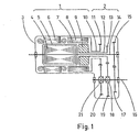
- a type of electric drive device of this invention includes an electromagnetic portion 1 and a transmission portion 2.
- Said electromagnetic portion includes a stator 6 capable of producing a rotating or an alternating magnetic field and fixed on the frame 3; three rotors capable of producing driving torque when running at asynchronous speed, respectively being the main rotor 4, the first auxiliary rotor 8, and the second auxiliary rotor 9. Said stator and every rotor respectively have their own cores. Rotors 4 and 8 respectively have their own closed winding 5 and closed winding 7, or each has a conductors equivalent to a closed winding, for conducting the induced rotor current.
- the electromagnetic portion has three closed magnetic circuits for conducting the main magnetic fluxes.
- the first magnetic circuit includes the stator core and a part of the core of the rotor 4, linking with the winding 5;
- the second magnetic circuit includes a part of the core of rotor 8 and the other part of the core 4, linking with winding 5 and 7;
- the third magnetic circuit includes the core of rotor 9 and the other part of the core of rotor 8, linking with the rotor winding 7.
- Said transmission portion includes transmission shafts 10,12,14; the shaft 16 being an output element; gears 11,13,15,17,19 and 20; the one-way clutches 18 and 21 being the automatic unloaded devices.
- Shafts 10 and 12 are hollow shafts.
- the shaft 12 is rotatably mounted on the shaft 14.
- the shaft 10 is rotatably mounted on shaft 12.
- Gears 11,13,15 and 17 are respectively connected with shafts 10,12,14 and 16.
- Gears 19 and 20 are respectively connected with the shaft 16 by the one-way clutches 18 and 21.
- Gears 11,13 and 15 are respectively meshing with gears 20,19, and 17.
- the rotor 4 As the main rotor, the rotor 4 is connected with shaft 14. While as the auxiliary rotors, the rotors 8 and 9 are respectively connected with the transmission shaft 10 and 12. When rotor 8 and 9 drive shaft 16 in the positive driving direction, the same as that of the rotor, the one-way clutches 18 and 21 are coupled. Conversely, if rotors 8 and 9 are respectively fixed and the shaft 16 is driven by the rotor 4 in its predetermined positive direction, the one-way clutch 18 and 21 will respectively be released.
- the speed ratios of the rotors for driving the shaft 16 are sequenced as follows: that of the auxiliary rotor 9 is the largest, the auxiliary rotor 8 the lesser and the main rotor 4 the minimum.
- a rotating or an alternating magnetic field will be generated by the stator 6.
- This magnetic field induces an electric current in winding 5 and causes the rotor 4 to produce a torque; the induced current in winding 5, in turn, will also induce a magnetic field in the above said second magnetic circuit including the core of the rotor 8 and induces a current in the winding 7.
- a torque will also be produced by the rotor 8.
- the induced current in the winding 7 will induce a magnetic field in the above said third magnetic circuit including the core of the rotor 9, and causes the rotor 9 to generate drive torque too. Therefore, said three rotors will simultaneously drive the transmission shaft 16 to rotate.
- auxiliary rotors 8 and 9 While said electric drive device is speeding up, the auxiliary rotors 8 and 9 will be accelerated until their speed are near or equal to the synchronous speed in accordance with the sequence of their respective speed ratio to the shaft 16. If the shaft 16 is still speeded up by the main rotor 4, its speed will consecutively exceed the speed of gears 19 and 20, thus the one-way clutches 18 and 21 will be consecutively released. Then, rotors 9 and 8 will consecutively change into their floating state.
- the shaft 14 of said electric drive device may also be used as an output element.
- the transmission element connected with the main rotor may be used as an output element of the device of this invention, if, correspondingly, the speed ratios of the auxiliary rotors driving the output element through the transmission portion are greater than one.
- auxiliary rotors in the electromagnetic portion of the electric drive device may be at least one, but its structure can be of various types.
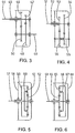
- a type of the electromagnetic portion of the electric drive device of this invention includes a stator 22 which is capable of producing a rotating or an alternating magnetic field; a main rotor 26 and an auxiliary rotor 25 that are capable of producing a torque at asynchronous speed. Said stator and rotor all have their own respective cores; said main rotor 26 has a closed winding, or a conductor equivalent to the winding, 23 for conducting the induced electric current therein. Different parts of the main rotor core 26 are respectively surrounded by the core of the stator 22 and the core of the auxiliary rotor 25, hence this electromagnetic portion has two closed magnetic circuits respectively linking with the main rotor winding 23.
- the first magnetic circuit includes the core of the stator 22 and a part of the core of the main rotor 26 and links with the stator winding;
- the second magnetic circuit includes the core of the auxiliary rotor 25 and theother part of the core of the main rotor 26.
- Said core of the auxiliary rotor 25 may include a solid block of steel or electrical pure iron.
- the transmission portion of the electric drive device provided in this invention may have many types of structures.
- a type of transmission portion of the electric drive device of this invention includes gears 46,47,49,50 and transmission shafts 44,45,48.
- the transmission shaft 45 is hollow and rotatably mounted on the transmission shaft 44.
- Gears 46 and 47 are connected to the transmission shafts 45 and 44 respectively.
- Gears 49 and 50 are both connected to the transmission shaft 48.
- Gears 46 and 47 are respectively meshed with the gears 50 and 49. So, there are fixed speed ratios between each of the transmission shafts 44,45 and the shaft 48.
- another type of transmission portion of the electric drive device of this invention includes gears 53 and 54 called as the first gear and second gear, respectively; duplex gear 56; transmission shafts 51 and 52 called as the first and second shaft respectively; and a fixed central spindle 55.
- the transmission shaft 52 is hollow and rotatably mounted on the shaft 51.
- Gears 53 and 54 are connected with transmission shafts 52 and 51, respectively.
- the duplex gear 56 is rotatably mounted on the spindle 55, its two gear rings are respectively meshed with gears 53 and 54. So, between shafts 51 and 52, there is a fixed speed ratio.
- another type of transmission portion of the electric drive device of this invention includes a transmission shaft 57, an inner gear 59, a planetary frame 60, a planet gear 61 and a central gear 62.
- the inner gear 59 is rotatably mounted on the transmission shaft 57
- the planetary frame 60 is connected with the transmission shaft 57
- the planet gear 61 is rotatably mounted on the planetary frame 60 and meshing with the central gear 62 and the inner gear 59 simultaneously
- the central gear 62 is connected with the frame 58.
- the inner gear 62 has a fixed speed ratio greater than one relative to the transmission shaft 57.
- another type of transmission portion of the electric drive device of this invention includes a transmission shaft 63, a central gear 64, a planet gear 65, a planetary frame 66 and an inner gear 67.
- the central gear 64 is rotatably mounted on the transmission shaft 63; the planetary frame 66 is connected with the shaft 63, the planetary gear 65 is rotatably mounted on the planetary frame 66 and meshing with the central gear 64 and the inner gear 67; the inner gear 67 is connected with the frame 68.
- the central gear 64 has a fixed speed ratio greater than one relative to the transmission shaft 63.
- the electric drive device in this invention may include any type of above mentioned electromagnetic portions and also any type of above mentioned transmission portions.
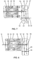
- Fig. 7 shows a type of the electric drive device in this invention.
- Said device includes an electromagnetic portion as shown in Fig. 2 and a transmission portion as shown in Fig. 3.
- the transmission shafts 45 and 44 in said transmission portion are connected with the main rotor 26 and the auxiliary rotor 25 in said electromagnetic portion, respectively.
- shaft 48 as an output element can be driven by both two said rotors.
- the speed ratio of main rotor 26 relative to the shaft 48 is less than that of the auxiliary rotor 25 relative to the same.
- a type of said electric drive device has a one-way clutch 69 used as its automatic unloaded device.
- the gear 49 in said transmission portion is connected with the shaft 48 by said one-way clutch 69.
- the one-way clutch can be released when the auxiliary rotor 25 is fixed and the main rotor 26 is rotating in its predetermined positive direction. While said electric drive device is speeding up, after the speed of the auxiliary rotor 25 is near, or equal to, the synchronous speed, and the main rotor 26 is accelerating further in its positive direction, the one-way clutch 69 will automatically be released, the auxiliary rotor 25 will float freely, for not bearing the load on the output shaft 48 again.
- said one-way clutch 69 may be mounted between any two connected transmission elements in the transmission chain from the auxiliary rotor 25 to the transmission shaft 48 which is the output element.
- said one-way clutch can be used for connecting the shaft 44 and the gear 47 or connecting the auxiliary rotor 25 the shaft 44.
- Fig. 8 shows another type of the electric drive device of this invention, including the electromagnetic portion shown in Fig. 2 and the transmission portion shown in Fig. 4.
- the transmission shafts 51 and 52 in said transmission portion are respectively connected with the main rotor 26 and the auxiliary rotor 25 in the electromagnetic portion.
- the transmission shaft 51 can be used as an output element for said electric drive device.
- the speed ratio of the auxiliary rotor 25 driving the shaft 51 through said transmission portion should be greater than one.
- a type of said electric drive device has a one-way clutch 70 used as its automatic unloaded device.
- the gear 54 of said transmission portion is connected with the shaft 51 by said one-way clutch 70.
- This one-way clutch can be released when the auxiliary rotor 25 is fixed and the main rotor 26 is rotating in its predetermined positive direction. Thereby, the auxiliary rotor 25 can change into its floating state after having a speed near or equal to the synchronous speed during the speeding up period of said electric drive device.
- Fig. 9 shows a type of the electric drive device of this invention, including the electromagnetic portion shown in Fig. 2 and the transmission portion shown in Fig. 5.
- the transmission shaft 57 and the inner gear 59 in said transmission portion are connected with the main rotor 26 and the auxiliary rotor 25 in said electromagnetic portion, respectively.
- the transmission shaft 57 can be used as an output element of said electric drive device.
- a type of said electric drive device has a one-way clutch 71 used as its automatic unloading device.
- a central gear 62 in said transmission portion is connected with the frame by this one-way clutch.
- Said one-way clutch 71 can be released when the auxiliary rotor 25 is fixed and the main rotor 26 rotating in its predetermined positive direction. So, with said electric drive device speeding up, after the auxiliary rotor 25 reaches the synchronous speed, the one-way clutch 71 will be automatically released and the auxiliary rotor 25 will change into its floating state.
- Fig. 10 shows another type of the electric drive device in this invention, including the electromagnetic portion shown in Fig. 2 and the transmission portion shown in Fig. 6.
- the transmission shaft 63 and the central gear 64 in said transmission portion are respectively coupled with the main rotor 26 and the auxiliary rotor 25 in said electromagnetic portion.
- the shaft 63 may be used as an output element of said electric drive device.
- a type of said electric drive device has a one-way clutch 72 used as the automatic unloaded device.
- Said inner gear 67 is connected with the frame by the one-way clutch 72.
- the one-way clutch 72 can be automatically released when the auxiliary rotor 25 is fixed and the main rotor 26 rotating in its positive direction. So, while the said drive device is speeding up, the auxiliary rotor 25 will shift to its floating state after its speed is near, or equal to, the synchronous speed.
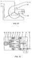
- a type of said electric drive device shown in Fig. 11 has an automatic unloaded device, in contrast to the above mentioned one-way clutch. Its auxiliary rotor 25 has a wire wound winding 73.
- Said automatic unloading device includes a set of automatic switch devices 74 having several pairs of normally closed contacts controlled by the rotational speed of a transmission element, such as the well-known centrifugal switch or speed relay. As shown in Fig. 11, the closed circuit of every phase of said auxiliary rotor winding has at least one pair of said normally closed contact connected in series. While said electric drive device is speeding up, when the speed of the auxiliary rotor reaches the predetermined speed that is usually near to the synchronous speed, each pair of the normally closed contacts 75 of said switch device will open. So, the induced current of every phase in winding 73 will be cut off, and no electromagnetic moment can be produced by the auxiliary rotor further. Thus, the auxiliary rotor will not be able to influence on the output of said electric drive device further.
- Fig. 12 shows a type of electric drive device of this invention having the electromagnetic portion shown in Fig. 2 and the transmission portion shown in Fig. 3.
- Said transmission shaft 44 has a protrusion step 93 and a spiral thread.
- said auxiliary rotor 25 has the spiral thread and a protrusion step matching with that of the shaft 44. If the spiral thread pair 94 consisting of the threads of shaft 44 and a rotor 25 is threaded up, the protrusion steps of said both members will be pressed to each other closely. The rotor 25, then, will be coupled with shaft 44 and hence can drive said output shaft 48. If said spiral thread pair 94 is screwed off, said auxiliary rotor 25 can then rotate freely.
- Said main motor 26 is connected with said transmission shaft 45. The speed ratio of said main rotor 26 driving the shaft 48 is less than that of the auxiliary rotor 25 driving the same.
- the direction of said spiral thread pair 94 is set in a manner such that, if the transmission shaft 44 is fixed and the auxiliary rotor is rotating in its predetermined positive direction, this spiral thread pair will be screwed up, then, the pair of protrusion steps 93 will also be pressed closely together.
- a type of said electric drive device is provided with a spring 95.
- said spring is forced deforming and, thereby, produces a force acting on the auxiliary rotor 25 and directed along the same direction as that of the axial displacement of the auxiliary rotor occurred while said spiral thread pair 94 was being screwed on.
- the core of the main rotor has a truncated circular conical portion 92 surrounded by the core of the auxiliary rotor.
- the air gap between the truncated circular conic portion 92 of the main rotor and the auxiliary rotor 25 is reducing due to the axial displacement of the latter.
- the electromagnetic force between the truncated circular conical portion 92 of the main rotor and the auxiliary rotor will include the component acting on said auxiliary rotor and directed along its axial displacement occurred while said spiral thread pair was being screwed on.
Landscapes
- Engineering & Computer Science (AREA)
- Power Engineering (AREA)
- General Engineering & Computer Science (AREA)
- Mechanical Engineering (AREA)
- Connection Of Motors, Electrical Generators, Mechanical Devices, And The Like (AREA)
- Synchronous Machinery (AREA)
Applications Claiming Priority (3)
| Application Number | Priority Date | Filing Date | Title |
|---|---|---|---|
| CN93105463 | 1993-04-27 | ||
| CN93105463 | 1993-04-27 | ||
| PCT/CN1994/000022 WO1994026016A1 (fr) | 1993-04-27 | 1994-04-05 | Dispositif electrodynamique a courant alternatif comprenant plusieurs rotors |
Publications (3)
| Publication Number | Publication Date |
|---|---|
| EP0703659A1 EP0703659A1 (en) | 1996-03-27 |
| EP0703659A4 EP0703659A4 (en) | 1997-06-16 |
| EP0703659B1 true EP0703659B1 (en) | 2000-08-30 |
Family
ID=4985736
Family Applications (1)
| Application Number | Title | Priority Date | Filing Date |
|---|---|---|---|
| EP94911822A Expired - Lifetime EP0703659B1 (en) | 1993-04-27 | 1994-04-05 | Multi-rotor a.c. electric drive device |
Country Status (7)
| Country | Link |
|---|---|
| US (1) | US5708314A (enExample) |
| EP (1) | EP0703659B1 (enExample) |
| JP (1) | JPH08509594A (enExample) |
| CN (1) | CN1038550C (enExample) |
| DE (1) | DE69425740T2 (enExample) |
| TW (1) | TW249869B (enExample) |
| WO (1) | WO1994026016A1 (enExample) |
Cited By (1)
| Publication number | Priority date | Publication date | Assignee | Title |
|---|---|---|---|---|
| RU224837U1 (ru) * | 2023-09-19 | 2024-04-05 | Общество с ограниченной ответственностью "КБ НП" | Трафаретный принтер для паяльной пасты |
Families Citing this family (39)
| Publication number | Priority date | Publication date | Assignee | Title |
|---|---|---|---|---|
| JP3379291B2 (ja) | 1995-07-31 | 2003-02-24 | 株式会社デンソー | 車両用駆動装置 |
| EP0798844A1 (en) * | 1996-03-28 | 1997-10-01 | Tai-Her Yang | The combined power driven device having a three-layered electromechanical structure with common structures |
| GB9612231D0 (en) * | 1996-06-12 | 1996-08-14 | Harris Michael A | Variable transmission apparatus |
| JP3000943B2 (ja) * | 1996-07-02 | 2000-01-17 | トヨタ自動車株式会社 | 動力出力装置およびその制御方法 |
| JP3000953B2 (ja) * | 1997-03-21 | 2000-01-17 | トヨタ自動車株式会社 | 動力出力装置およびその制御方法 |
| WO2000026053A1 (de) * | 1998-11-03 | 2000-05-11 | Robert Bosch Gmbh | Hybridgetriebe, insbesondere für kraftfahrzeuge |
| JP4069556B2 (ja) * | 1999-10-07 | 2008-04-02 | トヨタ自動車株式会社 | 動力出力装置の制御方法 |
| US6489692B1 (en) * | 1999-12-13 | 2002-12-03 | Capstone Turbine Corporation | Method and apparatus for controlling rotation of magnetic rotor |
| DE10250382A1 (de) * | 2002-10-29 | 2004-05-19 | Siemens Ag | Drehstrom-Asynchrongenerator |
| US20040200685A1 (en) * | 2003-04-14 | 2004-10-14 | Tai-Her Yang | Flexible & rigid bi-status coupler and application device |
| US7311993B2 (en) | 2003-09-04 | 2007-12-25 | Air Products And Chemicals, Inc. | Polyfluorinated boron cluster anions for lithium electrolytes |
| US20050099077A1 (en) * | 2003-11-10 | 2005-05-12 | Gerfast Sten R. | Magnetic coupling using magnets on a motor rotor |
| US7098563B2 (en) * | 2003-11-10 | 2006-08-29 | Tai-Her Yang | Drive system having a hollow motor main shaft and a coaxial, manually driven auxiliary shaft |
| US20050275303A1 (en) * | 2004-06-09 | 2005-12-15 | Tetmeyer Michael E | Differential flux permanent magnet machine |
| US7081696B2 (en) | 2004-08-12 | 2006-07-25 | Exro Technologies Inc. | Polyphasic multi-coil generator |
| US7465517B2 (en) | 2004-08-23 | 2008-12-16 | Air Products And Chemicals, Inc. | High purity lithium polyhalogenated boron cluster salts useful in lithium batteries |
| US7981388B2 (en) | 2004-08-23 | 2011-07-19 | Air Products And Chemicals, Inc. | Process for the purification of lithium salts |
| CN101501963B (zh) | 2006-06-08 | 2012-06-13 | Exro技术公司 | 多相多线圈发电机 |
| US7880355B2 (en) * | 2006-12-06 | 2011-02-01 | General Electric Company | Electromagnetic variable transmission |
| JP4693865B2 (ja) | 2007-08-27 | 2011-06-01 | 株式会社豊田中央研究所 | 動力伝達装置 |
| US8198743B2 (en) * | 2009-09-11 | 2012-06-12 | Honeywell International, Inc. | Multi-stage controlled frequency generator for direct-drive wind power |
| DE102011009608A1 (de) * | 2011-01-27 | 2012-08-02 | Audi Ag | Elektrischer Dämpfer |
| JP5621794B2 (ja) * | 2012-01-30 | 2014-11-12 | 株式会社デンソー | 磁気変調式複軸モータ |
| GB201210679D0 (en) | 2012-06-15 | 2012-08-01 | Jaguar Cars | Supercharger drive |
| ITMI20121339A1 (it) * | 2012-07-31 | 2014-02-01 | Emanuele Bisti | Macchina elettrica intelligente |
| US20140124276A1 (en) * | 2012-11-08 | 2014-05-08 | Caterpillar, Inc. | Dual Rotor Electric Drive |
| KR20150130551A (ko) * | 2013-03-20 | 2015-11-23 | 마그나 파워트레인 인크. | 탠덤 전동 펌프 |
| DE102014208867A1 (de) * | 2014-05-12 | 2015-11-12 | Robert Bosch Gmbh | Integration einer Elektromotoreneinheit in ein Getriebegehäuse |
| US9527600B2 (en) * | 2014-05-17 | 2016-12-27 | Hamilton Sundstrand Corporation | Ram air turbine generator assemblies |
| EP3001067B1 (de) * | 2014-09-23 | 2018-03-07 | Arnold Sudheimer | Getriebe, insbesondere Fahrzeuggetriebe |
| EP3082227A1 (de) * | 2015-04-14 | 2016-10-19 | Siemens Aktiengesellschaft | Rotor einer asynchronmaschine |
| CN105553202B (zh) * | 2016-03-04 | 2018-11-23 | 重庆大学 | 多级定转子组合式电机 |
| CN106515406A (zh) * | 2016-11-18 | 2017-03-22 | 精进电动科技股份有限公司 | 同轴多电机驱动系统和设置有同轴多电机驱动系统的车辆 |
| JP2020521418A (ja) | 2017-05-23 | 2020-07-16 | ディーピーエム テクノロジーズ インク. | 可変コイル結線システム |
| CA3111823A1 (en) | 2018-09-05 | 2020-03-12 | Dpm Technologies Inc. | Systems and methods for intelligent energy storage and provisioning using an energy storage control system |
| US11722026B2 (en) | 2019-04-23 | 2023-08-08 | Dpm Technologies Inc. | Fault tolerant rotating electric machine |
| CN113543437A (zh) * | 2020-04-22 | 2021-10-22 | 合肥美亚光电技术股份有限公司 | X射线发生装置和医用成像设备 |
| WO2022232904A1 (en) | 2021-05-04 | 2022-11-10 | Exro Technologies Inc. | Battery control systems and methods |
| CN117337545A (zh) | 2021-05-13 | 2024-01-02 | Exro技术公司 | 驱动多相电机的线圈的方法及装置 |
Family Cites Families (19)
| Publication number | Priority date | Publication date | Assignee | Title |
|---|---|---|---|---|
| US2864017A (en) * | 1955-11-28 | 1958-12-09 | Waltscheff Dimo Dimitroff | Inducto-motive power apparatus with a plurality of rotors |
| US2860296A (en) * | 1957-11-20 | 1958-11-11 | Gen Electric | Dual-voltage alternating-current motor |
| FR1332959A (fr) * | 1962-08-31 | 1963-07-19 | Ensemble de moteurs électriques à vitesse variable | |
| FR1576528A (enExample) * | 1968-05-17 | 1969-08-01 | ||
| DE2138898C3 (de) * | 1971-08-04 | 1975-10-02 | Fa. Arnold Mueller, 7312 Kirchheim | Regel barer Asynchronmotor mit einem Mehrfachrotorsystem |
| CH591178A5 (enExample) * | 1972-11-03 | 1977-09-15 | Anvar | |
| US3864017A (en) * | 1973-05-31 | 1975-02-04 | American Optical Corp | Optical fiber arc-to-line converter |
| DE2332868C2 (de) * | 1973-06-28 | 1975-05-22 | Fa. Arnold Mueller, 7312 Kirchheim | Regelbarer Drehstrommotor mit Zwischenrotor und Innenläufer |
| US3973137A (en) * | 1975-06-16 | 1976-08-03 | Dezso Donald Drobina | Multi-rotor electric motor |
| SU875546A1 (ru) * | 1979-06-18 | 1981-10-23 | Фрунзенский политехнический институт | Асинхронный двухроторный электродвигатель |
| US4488069A (en) * | 1981-04-07 | 1984-12-11 | Sigma Instruments Inc. | Stepping motor |
| FR2504992B1 (fr) * | 1981-04-30 | 1986-11-14 | Valbrev | Combinaison d'une turbo-machine de compression ou de detente et d'un moteur electrique |
| FR2517137B1 (fr) * | 1981-11-25 | 1985-11-15 | Cibie Pierre | Machine electrique tournante formant notamment variateur de vitesse ou convertisseur de couple |
| US4625160A (en) * | 1984-12-17 | 1986-11-25 | Sundstrand Corporation | Variable speed constant frequency generating system |
| DE3640397C1 (de) * | 1986-11-26 | 1988-01-07 | Philips Patentverwaltung | Antriebsvorrichtung fuer ein kleines Haushaltsgeraet |
| CN1006671B (zh) * | 1988-04-23 | 1990-01-31 | 辽宁省能源研究所 | 一种绕线型异步电动机及其制造方法 |
| JP2569360B2 (ja) * | 1988-11-25 | 1997-01-08 | 多摩川精機株式会社 | 発電機 |
| US5053664A (en) * | 1989-01-18 | 1991-10-01 | Aisan Kogyo Kabushiki Kaisha | Motor-driven fuel pump |
| CN1063183A (zh) * | 1991-01-10 | 1992-07-29 | 江西省粮油机械厂 | 交流双转子多速异步电动机 |
-
1994
- 1994-04-05 CN CN94191749A patent/CN1038550C/zh not_active Expired - Fee Related
- 1994-04-05 DE DE69425740T patent/DE69425740T2/de not_active Expired - Fee Related
- 1994-04-05 WO PCT/CN1994/000022 patent/WO1994026016A1/zh not_active Ceased
- 1994-04-05 JP JP6523717A patent/JPH08509594A/ja active Pending
- 1994-04-05 EP EP94911822A patent/EP0703659B1/en not_active Expired - Lifetime
- 1994-04-05 US US08/535,166 patent/US5708314A/en not_active Expired - Fee Related
- 1994-04-15 TW TW083103363A patent/TW249869B/zh active
Cited By (1)
| Publication number | Priority date | Publication date | Assignee | Title |
|---|---|---|---|---|
| RU224837U1 (ru) * | 2023-09-19 | 2024-04-05 | Общество с ограниченной ответственностью "КБ НП" | Трафаретный принтер для паяльной пасты |
Also Published As
| Publication number | Publication date |
|---|---|
| AU676549B2 (en) | 1997-03-13 |
| DE69425740T2 (de) | 2001-04-19 |
| JPH08509594A (ja) | 1996-10-08 |
| CN1038550C (zh) | 1998-05-27 |
| TW249869B (enExample) | 1995-06-21 |
| AU6422894A (en) | 1994-11-21 |
| WO1994026016A1 (fr) | 1994-11-10 |
| US5708314A (en) | 1998-01-13 |
| EP0703659A1 (en) | 1996-03-27 |
| EP0703659A4 (en) | 1997-06-16 |
| DE69425740D1 (de) | 2000-10-05 |
Similar Documents
| Publication | Publication Date | Title |
|---|---|---|
| EP0703659B1 (en) | Multi-rotor a.c. electric drive device | |
| KR100337688B1 (ko) | 유도전동기로의전력공급방법 | |
| US4107583A (en) | Dynamoelectric machine winding arrangements, dynamoelectric machines incorporating same and methods of operating such dynamoelectric machines | |
| US4296344A (en) | Multi-speed motor | |
| CA1281065C (en) | Parallel resonant single phase motor | |
| EP0441970B1 (en) | Reluctance type motor | |
| US4322665A (en) | Two speed single phase motor | |
| US4447737A (en) | Variable frequency induction generator | |
| US2864016A (en) | Electromagnetic transmission torque converter | |
| GB1574015A (en) | Electric motor | |
| US4635349A (en) | Method of making single phase multi-speed motor | |
| JPH0681555B2 (ja) | 可変速発電装置及び方法 | |
| US2881338A (en) | Variable speed alternating current motor | |
| US2174662A (en) | Transmission | |
| CN101825146A (zh) | 自适应磁流变离合器 | |
| HK1017973A (en) | Multi-rotor a.c. electrodynamic device | |
| CN111130292A (zh) | 一种磁阻型软启动器 | |
| EP0514869B1 (en) | Variable speed geared motor and a series thereof | |
| RU2012980C1 (ru) | Электромагнитный редуктор | |
| JPH0919116A (ja) | 誘導電動機による駆動装置及びその始動運転方法 | |
| CN201742283U (zh) | 自适应电磁离合器 | |
| US3060336A (en) | Electric motor | |
| CN101826788B (zh) | 自适应电磁离合器 | |
| KR101542923B1 (ko) | 3상 특수 농형 극수 변환 전동기 및 이를 포함하는 2속 호이스트 | |
| US3034030A (en) | Rotary electric machines |
Legal Events
| Date | Code | Title | Description |
|---|---|---|---|
| PUAI | Public reference made under article 153(3) epc to a published international application that has entered the european phase |
Free format text: ORIGINAL CODE: 0009012 |
|
| 17P | Request for examination filed |
Effective date: 19951124 |
|
| AK | Designated contracting states |
Kind code of ref document: A1 Designated state(s): DE FR GB |
|
| A4 | Supplementary search report drawn up and despatched | ||
| AK | Designated contracting states |
Kind code of ref document: A4 Designated state(s): DE FR GB |
|
| 17Q | First examination report despatched |
Effective date: 19980513 |
|
| GRAG | Despatch of communication of intention to grant |
Free format text: ORIGINAL CODE: EPIDOS AGRA |
|
| GRAG | Despatch of communication of intention to grant |
Free format text: ORIGINAL CODE: EPIDOS AGRA |
|
| GRAG | Despatch of communication of intention to grant |
Free format text: ORIGINAL CODE: EPIDOS AGRA |
|
| GRAH | Despatch of communication of intention to grant a patent |
Free format text: ORIGINAL CODE: EPIDOS IGRA |
|
| GRAH | Despatch of communication of intention to grant a patent |
Free format text: ORIGINAL CODE: EPIDOS IGRA |
|
| GRAA | (expected) grant |
Free format text: ORIGINAL CODE: 0009210 |
|
| RTI1 | Title (correction) |
Free format text: MULTI-ROTOR A.C. ELECTRIC DRIVE DEVICE |
|
| AK | Designated contracting states |
Kind code of ref document: B1 Designated state(s): DE FR GB |
|
| REF | Corresponds to: |
Ref document number: 69425740 Country of ref document: DE Date of ref document: 20001005 |
|
| ET | Fr: translation filed | ||
| PLBE | No opposition filed within time limit |
Free format text: ORIGINAL CODE: 0009261 |
|
| STAA | Information on the status of an ep patent application or granted ep patent |
Free format text: STATUS: NO OPPOSITION FILED WITHIN TIME LIMIT |
|
| 26N | No opposition filed | ||
| REG | Reference to a national code |
Ref country code: GB Ref legal event code: IF02 |
|
| PGFP | Annual fee paid to national office [announced via postgrant information from national office to epo] |
Ref country code: GB Payment date: 20030402 Year of fee payment: 10 |
|
| PGFP | Annual fee paid to national office [announced via postgrant information from national office to epo] |
Ref country code: FR Payment date: 20030408 Year of fee payment: 10 |
|
| PGFP | Annual fee paid to national office [announced via postgrant information from national office to epo] |
Ref country code: DE Payment date: 20030417 Year of fee payment: 10 |
|
| PG25 | Lapsed in a contracting state [announced via postgrant information from national office to epo] |
Ref country code: GB Free format text: LAPSE BECAUSE OF NON-PAYMENT OF DUE FEES Effective date: 20040405 |
|
| PG25 | Lapsed in a contracting state [announced via postgrant information from national office to epo] |
Ref country code: DE Free format text: LAPSE BECAUSE OF NON-PAYMENT OF DUE FEES Effective date: 20041103 |
|
| GBPC | Gb: european patent ceased through non-payment of renewal fee | ||
| PG25 | Lapsed in a contracting state [announced via postgrant information from national office to epo] |
Ref country code: FR Free format text: LAPSE BECAUSE OF NON-PAYMENT OF DUE FEES Effective date: 20041231 |
|
| REG | Reference to a national code |
Ref country code: FR Ref legal event code: ST |
|
| REG | Reference to a national code |
Ref country code: HK Ref legal event code: WD Ref document number: 1017973 Country of ref document: HK |