EP0703571B1 - Magnetic head - Google Patents
Magnetic head Download PDFInfo
- Publication number
- EP0703571B1 EP0703571B1 EP95114758A EP95114758A EP0703571B1 EP 0703571 B1 EP0703571 B1 EP 0703571B1 EP 95114758 A EP95114758 A EP 95114758A EP 95114758 A EP95114758 A EP 95114758A EP 0703571 B1 EP0703571 B1 EP 0703571B1
- Authority
- EP
- European Patent Office
- Prior art keywords
- magnetic
- ferrite
- magnetic head
- crystal
- magnetic core
- Prior art date
- Legal status (The legal status is an assumption and is not a legal conclusion. Google has not performed a legal analysis and makes no representation as to the accuracy of the status listed.)
- Expired - Lifetime
Links
Images


Classifications
-
- G—PHYSICS
- G11—INFORMATION STORAGE
- G11B—INFORMATION STORAGE BASED ON RELATIVE MOVEMENT BETWEEN RECORD CARRIER AND TRANSDUCER
- G11B5/00—Recording by magnetisation or demagnetisation of a record carrier; Reproducing by magnetic means; Record carriers therefor
- G11B5/127—Structure or manufacture of heads, e.g. inductive
- G11B5/187—Structure or manufacture of the surface of the head in physical contact with, or immediately adjacent to the recording medium; Pole pieces; Gap features
- G11B5/1875—"Composite" pole pieces, i.e. poles composed in some parts of magnetic particles and in some other parts of magnetic metal layers
- G11B5/1877—"Composite" pole pieces, i.e. poles composed in some parts of magnetic particles and in some other parts of magnetic metal layers including at least one magnetic thin film
- G11B5/1878—"Composite" pole pieces, i.e. poles composed in some parts of magnetic particles and in some other parts of magnetic metal layers including at least one magnetic thin film disposed immediately adjacent to the transducing gap, e.g. "Metal-In-Gap" structure
-
- G—PHYSICS
- G11—INFORMATION STORAGE
- G11B—INFORMATION STORAGE BASED ON RELATIVE MOVEMENT BETWEEN RECORD CARRIER AND TRANSDUCER
- G11B5/00—Recording by magnetisation or demagnetisation of a record carrier; Reproducing by magnetic means; Record carriers therefor
- G11B5/127—Structure or manufacture of heads, e.g. inductive
- G11B5/133—Structure or manufacture of heads, e.g. inductive with cores composed of particles, e.g. with dust cores, with ferrite cores with cores composed of isolated magnetic particles
- G11B5/1335—Assembling or shaping of elements
-
- G—PHYSICS
- G11—INFORMATION STORAGE
- G11B—INFORMATION STORAGE BASED ON RELATIVE MOVEMENT BETWEEN RECORD CARRIER AND TRANSDUCER
- G11B5/00—Recording by magnetisation or demagnetisation of a record carrier; Reproducing by magnetic means; Record carriers therefor
- G11B5/127—Structure or manufacture of heads, e.g. inductive
- G11B5/187—Structure or manufacture of the surface of the head in physical contact with, or immediately adjacent to the recording medium; Pole pieces; Gap features
- G11B5/1871—Shaping or contouring of the transducing or guiding surface
-
- G—PHYSICS
- G11—INFORMATION STORAGE
- G11B—INFORMATION STORAGE BASED ON RELATIVE MOVEMENT BETWEEN RECORD CARRIER AND TRANSDUCER
- G11B5/00—Recording by magnetisation or demagnetisation of a record carrier; Reproducing by magnetic means; Record carriers therefor
- G11B5/127—Structure or manufacture of heads, e.g. inductive
- G11B5/187—Structure or manufacture of the surface of the head in physical contact with, or immediately adjacent to the recording medium; Pole pieces; Gap features
- G11B5/193—Structure or manufacture of the surface of the head in physical contact with, or immediately adjacent to the recording medium; Pole pieces; Gap features the pole pieces being ferrite or other magnetic particles
-
- G—PHYSICS
- G11—INFORMATION STORAGE
- G11B—INFORMATION STORAGE BASED ON RELATIVE MOVEMENT BETWEEN RECORD CARRIER AND TRANSDUCER
- G11B5/00—Recording by magnetisation or demagnetisation of a record carrier; Reproducing by magnetic means; Record carriers therefor
- G11B5/127—Structure or manufacture of heads, e.g. inductive
- G11B5/187—Structure or manufacture of the surface of the head in physical contact with, or immediately adjacent to the recording medium; Pole pieces; Gap features
- G11B5/255—Structure or manufacture of the surface of the head in physical contact with, or immediately adjacent to the recording medium; Pole pieces; Gap features comprising means for protection against wear
Definitions
- This invention relates to a magnetic head employed for e.g., a video tape recorder. More particularly, it relates to such magnetic head having improved abrasion resistance.
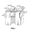
- a magnetic head made up of a pair of magnetic core halves 33m, 33n bonded to each other with a magnetic gap g3 defined between abutting surfaces of the magnetic core halves 33m, 33n.
- the magnetic core halves 33m, 33n are formed by bonding single-crystal ferrite pieces 31m, 31n and polycrystal ferrite pieces 32m, 32n to each other to form a junction ferrite.
- the magnetic head thus formed has its upper most portion, that is a surface configured for having sliding contact with a magnetic recording medium, constituted by the single-crystal ferrite pieces 31m, 31n, while having its lower most portion, that is its bottom surface, constituted by the polycrystal ferrite pieces 32m, 32n.
- the magnetic gap g3 formed at the junction portion of the magnetic core halves 33m, 33n and the top of the surfaces of the single-crystal ferrite pieces 31m, 31n on which slides the magnetic recording medium, referred to hereinafter as an R-TOP, are designed to be coincident with each other, so that the magnetic recording medium will be contacted with the magnetic head at the site of the magnetic gap g3.
- This type of the magnetic head is effective to reduce the sliding noise since the single-crystal ferrite pieces 31m, 31n are of a small volume and the polycrystal ferrite pieces 32m, 32n take up a major portion of the volume of the magnetic head.
- a so-called R-TOP offset T is incurred between the position R of the R-TOP and the position G of the magnetic gap g3, as shown in Figs. 2 and 3, so that the position G of the magnetic gap g3 becomes non-coincident with the position R of the R-TOP thus deteriorating abutting contact between the magnetic recording medium and the magnetic head. That is, the contact position between the magnetic recording medium and the magnetic head is an offset position R due to the partial advancing wear, so that the magnetic recording medium cannot be contacted with the magnetic head at the site of the magnetic gap g3.
- Prior art document GB-A-2 012 468 discloses a magnetic head in which each of the two magnetic cores is made of a mono-crystal ferrite and gap surfaces are formed by ⁇ 111 ⁇ crystal planes.
- the present invention provides a magnetic head as specified in claim 1.
- a magnetic head has a pair of magnetic core halves integrally bonded to each other, each magnetic core half being formed by a single-crystal ferrite piece and a polycrystal ferrite piece bonded together to constitute a junction ferrite, with a magnetic gap being defined between abutting surfaces of the magnetic core halves.
- the single-crystal ferrite pieces are arranged towards the abutting surfaces of the magnetic core halves and the polycrystal ferrite pieces are arranged on the opposite side of the abutting surfaces with respect to the single-crystal ferrite pieces
- the surface of the single-crystal ferrite piece having sliding contact with the magnetic recording medium is a ⁇ 211 ⁇ plane, while the gap surface thereof is a ⁇ 111 ⁇ plane and the surface thereof corresponding to the lateral surface of the magnetic head is a ⁇ 110 ⁇ plane.
- the directions of the ⁇ 100> crystal axes within the plane ⁇ 110 ⁇ are symmetrical to each other on both sides of the magnetic gap.
- polycrystal ferrite there exist numerous pores in the polycrystal ferrite. If, when the polycrystal ferrite is exposed on the surface of the magnetic head configured for having sliding contact with the recording medium, there exist pores in the polycrystal ferrite, the sliding characteristics of the recording medium tend to be deteriorated due to these pores. It is therefore preferred to use polycrystal ferrite in which the number of the pores is diminished. Specifically, it is preferred to use polycrystal ferrite having its pores reduced in number by being previously processed with hot isostatic pressing.
- the magnetic head of the present invention may be any magnetic head on the condition that a pair of magnetic core halves are integrally bonded to each other and a magnetic gap is formed between abutting surfaces of the magnetic core halves.
- the magnetic head may be of a so-called metal-in-gap type in which a thin magnetic metal film is arranged on abutting surfaces of the magnetic core halves, or of a so-called tilted sendust sputter type in which a thin magnetic metal film is arranged on each of the abutting surfaces of the magnetic core halves and the boundary surface between the magnetic core half and the thin magnetic metal film is inclined at a pre-set angle relative to the magnetic gap surface.
- the magnetic head of the present invention since the major portion of the surface thereof configured for having sliding contact with the magnetic recording medium, excepting the region in the vicinity of the magnetic gap, is formed of polycrystal ferrite which undergoes uniform abrasion, so that the two magnetic core halves exhibit substantially equal abrasion characteristics. The result is that the two magnetic core halves are worn out equally and hence are not subjected to partial advancing abrasion.
- the slide noise may be suppressed to a lower value.
- the magnetic gap is formed by a single-crystal ferrite in which its surface having sliding contact with the magnetic recording medium is a ⁇ 211 ⁇ plane, its magnetic gap surface, representing an abutting surface of the magnetic core half, is a ⁇ 111 ⁇ plane and its surface corresponding to the lateral side of the magnetic head is a ⁇ 110 ⁇ plane, and in which the directions of the ⁇ 100> crystal axes in the plane ⁇ 110 ⁇ corresponding to the lateral surface of the magnetic head axes are symmetrical to each other on both sides of the magnetic gap, superior electro-magnetic conversion characteristics may be achieved.
- the magnetic core halves exhibit substantially equal abrasion resistance characteristics, and undergo abrasion in a similar manner to each other, there is no risk of partial advancing wear so that satisfactory abrasion characteristics may be achieved.
- the polycrystal ferrite is processed by HIP processing, there exist scarcely any pores in the polycrystal ferrite portion of the magnetic head, so that excellent sliding characteristics of the recording medium may be realized even although the polycrystal ferrite is exposed on the surface of the magnetic head adapted to have sliding contact with the magnetic recording medium.
- the magnetic head of the present invention utilizes a junction ferrite, it becomes possible to suppress the slide contact noise to a small value and to achieve satisfactory slide contact characteristics of the recording medium.
- the magnetic head of the present embodiment is comprised of a pair of magnetic core halves 3m, 3n, as shown in Fig.4.
- the magnetic core half 3m is comprised of junction ferrite made up of a single-crystal ferrite piece 1m and a polycrystal ferrite piece 2m bonded to each other
- the magnetic core half 3n is comprised of junction ferrite made up of a single-crystal ferrite piece 1n and a polycrystal ferrite piece 2n bonded to each other.
- the magnetic core halves 3m, 3n, thus bonded together, constitute a closed magnetic path.
- the magnetic core halves 3m, 3n are formed with track width control grooves 4m, 4n, respectively, on both lateral sides of the magnetic gap g1, so that the abutting surfaces of the magnetic core halves 3m, 3n will be substantially trapezoidal in configuration.
- the trapezoidal shape is defined by a flat side defined by the flat gap forming surface defining the magnetic gap g1 and by the track width control grooves 4m, 4n which are inclined curved surfaces in both lateral sides of the gap forming surface.
- the abutting surfaces of the magnetic core halves 3m, 3n are formed with substantially rectangular grooves as winding slots 5m, 5n, respectively, for placing coils, not shown. These winding slots are formed as through-slots extending along the thickness of the magnetic core in the magnetic core halves 3m, 3n, respectively, for facing each other.
- the magnetic core halves 3m, 3n are unified to each other by fused glass 8.
- junction surfaces between the single-crystal ferrite pieces 1m, 1n and the polycrystal ferrite pieces 2m, 2n, constituting the magnetic core halves 3m, 3n, run parallel to the gap surface which represents the abutting surface of the magnetic core halves 3m, 3n, with the single-crystal ferrite pieces 1m, 1n and the polycrystal ferrite pieces 2m, 2n being on the abutting surfaces and on the opposite side surfaces of the magnetic core halves 3m, 3n, respectively.
- a portion near the magnetic gap g1 and the remaining portion of the surface of the magnetic head contacted by the magnetic recording medium are constituted by the single-crystal ferrite pieces 1m, 1n and by the polycrystal ferrite pieces 2m, 2n, respectively.
- the distance between the junction surface of the single-crystal ferrite pieces 1m, 1n and the polycrystal ferrite pieces 2m, 2n and the gap surface, that is the thickness t1 of the single-crystal ferrite piece 1m or 1n, is selected to be smaller than the abutting length of the magnetic recording medium to the magnetic head along the sliding direction of the magnetic recording medium relative to the magnetic head.
- the reason therefor is that, for prohibiting partial advancing wear, the magnetic recording medium is configured to slide not only in contact with the vicinity of the magnetic gap g1 delimited by the single-crystal ferrite pieces 1m, 1n but also in contact with the polycrystal ferrite pieces 2m, 2n exhibiting equal abrasion characteristics.
- the thickness t1 of each of the single-crystal ferrite pieces 1m, 1n is set to approximately 50 ⁇ m.
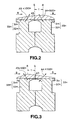
- each of the single-crystal ferrite pieces 1m, 1n is so set that its surface 1a having sliding contact with the magnetic recording medium is a ⁇ 211 ⁇ plane, its gap surface 1b is a ⁇ 111 ⁇ plane and its lateral surface 1c corresponding to the lateral side of the magnetic head is a ⁇ 110 ⁇ plane.
- the direction of the ⁇ 100> crystal axis of the single-crystal ferrite piece 1m is set so as to be symmetrical with respect to the direction of.the ⁇ 100> crystal axis of the single crystal ferrite piece 1n with the magnetic gap g1 in-between.
- these directions of the ⁇ 100> crystal axes are set so that an angle ⁇ 1 between the direction A1 of the ⁇ 100> crystal axis of the single-crystal ferrite 1m of one of the magnetic core halves and the sliding direction B1 of the recording medium is approximately 125° and an angle ⁇ 2 between the direction A2 of the ⁇ 100> crystal axis of the single-crystal ferrite 1n of the remaining magnetic core half and the sliding direction B1 of the recording medium is approximately 55° , as shown in Fig.5.
- an angle ⁇ 1 between the direction Al of the ⁇ 100> crystal axis of the single-crystal ferrite 1m of one of the magnetic core halves and the sliding direction B1 of the recording medium is approximately 55' and an angle ⁇ 2 between the direction of the ⁇ 100> crystal axis of the single-crystal ferrite 1n of the remaining magnetic core half and the sliding direction B1 of the recording medium is approximately 125°, as shown in Fig.6.
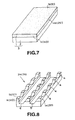
- a single-crystal ferrite substrate 1 in the form of a flat plate and a polycrystal ferrite substrate 2 in the form of a flat plate are bonded to each other to form a junction ferrite substrate 3 in the form of a flat plate, as shown in Fig.7.
- a Mn-Zn single-crystal ferrite piece is preferably employed as the single-crystal ferrite substrate 1.
- the single-crystal ferrite substrate 1 is placed so that the sliding contact surface 1a with the recording medium, gap surface 1b and the lateral surface corresponding to the lateral side of the magnetic head 1c correspond to a ⁇ 211 ⁇ plane, a ⁇ 111 ⁇ plane and a ⁇ 110 ⁇ plane, respectively, and the single-crystal ferrite substrate 1 is bonded to the polycrystal ferrite substrate 2 so that the resulting junction surface will be parallel to the gap surface 1b.
- the thickness of the single-crystal ferrite substrate 1 is selected to be approximately 50 ⁇ m.
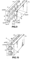
- a winding slot 5 and a glass charging slot 6 are formed in the gap surface 1b in a direction parallel to the slide contact surface 1a.
- a plurality of track width control grooves 4 are formed at a pre-set constant pitch in the gap surface 1b in a direction normal to the winding slot 5 and the glass-charging slot 6.
- the gap surface 1b is then ground to a mirror finish in order to produce a pair of magnetic core half blocks 7m, 7n.
- the gap film, formed on the magnetic core half blocks 7m, 7n, is to be a magnetic gap, and has a film thickness equal to one half the gap length of the magnetic head being prepared.
- the magnetic core half blocks 7m, 7n are placed so that the respective gap surfaces 1b will face each other.
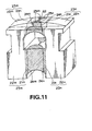
- Glass rods are inserted in the winding slots 5 facing each other and the glass charging slots 6 similarly facing each other, and are fused, as a result of which the magnetic core half blocks 7m, 7n are bonded to each other by the fused glass rods, as shown in Fig.10, for forming a magnetic core block 9.
- the magnetic core half blocks 7m, 7n may also be fused by low-temperature heat-diffusion bonding by thermal diffusion of metal films, instead of by bonding by glass fusion described above.
- thin metal films such as Au films, are formed on the abutting surfaces of the magnetic core half blocks and abutted to each other under a pre-set pressure and under application of a low temperature for heating for effecting the bonding.
- the slide contact surface of the magnetic core block 9 is ground to a cylindrical finish, while abutting width control grooves are formed at a pre-set azimuth angle at both ends of the slide contact surface for the magnetic recording medium for delimiting the abutment width of the magnetic recording medium relative to the magnetic head.
- the magnetic core block 9 is finally sliced into plural magnetic cores. Each magnetic core, thus sliced out of the magnetic core block, is trimmed to a desired shape in order to produce a magnetic head shown in Fig.4.
- the abrasion characteristics of the magnetic head were evaluated in comparison with a conventional magnetic head.
- the magnetic heads were mounted on a deck for beta-cam SP manufactured by SONY CORPORATION (machine type, BVW-50) and a magnetic tape for beta-cam SP manufactured by SONY CORPORATION (trade name, BCT-90ML) was run for 24 hours under an environment of 25°C and 80% RH, and the R-TOP offset, that is the distance between the top of the slide contact surface for the magnetic recording medium and the magnetic gap, was subsequently measured.
- the R-TOP offset was measured using a interference fringe microscope.
- the measured results of the R-TOP offset are shown in Table 1.
- magnetic head of Example 1 conventional magnetic head R-TOP offset 30 ⁇ m 140 ⁇ m
- the R-TOP offset is significantly diminished as compared to that of the conventional magnetic head. That is, the magnetic head of the present embodiment may be said to be less susceptible to partial advancing wear while being excellent in abrasion characteristics.
- the magnetic head of the present embodiment is a metal-in-gap type magnetic head and is configured similarly to the first embodiment except that thin magnetic metal films 24m, 24n are formed on abutting surfaces of magnetic core halves 23m, 23n. That is, the magnetic head of the present embodiment is fabricated in such a manner that a pair of magnetic core halves 23m, 23n, made up of junction ferrite pieces produced by bonding single-crystal ferrite pieces 21m, 21n and polycrystal ferrite pieces 22m, 22n, are bonded to each other with the interposition of the thin magnetic metal films 24m, 24n formed to the abutting surfaces of the magnetic core halves 23m, 23n.
- a closed magnetic path is defined by the magnetic core halves 23m, 23n and the thin magnetic metal films 24m, 24n, and a magnetic gap g2 with a pre-set azimuth angle, operating as a recording/playback gap, is formed between these abutting surfaces.
- the thin magnetic metal films 24m, 24n are formed on the abutting surfaces of the magnetic core halves 23m, 23n as continuous films extending from the front to the back sides. That is, the thin magnetic metal films 24m, 24n are formed on the magnetic core halves 23m, 23n as continuous films extending on the magnetic gap forming surfaces and on the track width control grooves 25m, 25n.
- the material of the thin magnetic metal films 24m, 24n it is sufficient if it is a magnetic metal material having high saturation magnetic flux density and superior soft magnetic properties.
- Such material may be enumerated by crystalline materials, such as Fe alloys, Fe-Ni based alloys, Fe-C based alloys, Fe-Al-Si based alloys, Fe-Ga-Si based alloys, Fe-Al-Ge based alloys, Fe-Ga-Ge based alloys, Fe-Si-Ge based alloys, Fe-Co-Si based alloys, Fe-Ru-Ga-Si based alloys or Fe-Co-Si-Al based alloys, and amorphous alloys, such as Co-Zr-Nb, Co-Zr-Nb-Ta, Co-Zr-Pd-Mo or Co-Zr-Pd-Ru alloys.
- crystalline materials such as Fe alloys, Fe-Ni based alloys, Fe-C based alloys
- amorphous alloys such as alloys of one or more elements selected from among Fe, Ni and Co and one or more elements selected from among P, C, B and Si, metal-metalloid based amorphous alloys, mainly composed of these amorphous alloys and admixed with Al, Be, Sn, In, Mo, W, Ti, Mn, Cr, Zr, Hf and Nb, alloys mainly composed of transition elements, such as Co-Zr or Co-Hf, and metal-metal based amorphous alloys mainly composed of these elements and admixed with rare earth elements, may also be employed.
- the thin magnetic metal films 24m, 24n may be sole layers, these may also be laminated alternately with non-magnetic insulating layers for diminishing eddy current losses in a high frequency range.
- the non-magnetic insulating layers may be formed of such materials as SiO 2 , Ta 2 O 5 , Al 2 O 3 , ZrO 2 or Si 3 O 4 .
- a pair of magnetic core half blocks are prepared in the same way as with the first embodiment, and a magnetic metal material is deposited on the gap surface of each magnetic core half block to a pre-set thickness.
- the gap film of a non-magnetic material, such as SiO 2 may then be formed on the thin magnetic metal film.
- the magnetic head may be fabricated in the same way as with the first embodiment except forming the thin magnetic metal film in this manner.
- the magnetic head of the present second embodiment since the slide contact surface for the magnetic recording medium, except the region in the vicinity of the magnetic gap, is formed of polycrystal ferrite which undergoes uniform abrasion, the magnetic core halves exhibit substantially equal resistance against abrasion so that partial advancing abrasion may be prohibited as in the case of the magnetic head of the first embodiment.
- the magnetic head of the present third embodiment is manufactured in the same way as the magnetic head of the first or second embodiment except employing a polycrystal ferrite processed by hot isostatic pressing (HIP processing).
- HIP processing hot isostatic pressing
- starting ferrite powders are wet-mixed, dried and press-molded t a block of a pre-set size.
- This block is sintered for about five hours at a temperature of approximately 1300°C for producing a polycrystal ferrite substrate.
- Numerous pores of a size on the order of 2 to 5 ⁇ m are present in the polycrystal ferrite substrate.
- the porosity of the polycrystal ferrite substrate is on the order of 4 to 5%.
- This polycrystal ferrite substrate is then processed by HIP processing which is carried out for two to five hours under a pressure of approximately 100 MPa and at a temperature of approximately 1200°C, using e.g., an Ar gas.
- HIP processing By such HIP processing of the polycrystal ferrite substrate, the pores are diminished in number, such that the porosity of the polycrystal ferrite substrate is 0.1% or lower.
- a magnetic head is produced, in the same way as in the first and second embodiments.
- the magnetic head of the present embodiment employing the polycrystal ferrite processed by HIP processing, since there exist scarcely any pores in the polycrystal ferrite portion, there is no risk of damages done to the surface of the magnetic recording medium by pore edges or of spacing produced in the pores due to magnetic powders clogged therein, so that satisfactory sliding characteristics may be assured for the recording medium.
Landscapes
- Engineering & Computer Science (AREA)
- Manufacturing & Machinery (AREA)
- Magnetic Heads (AREA)
Description
| magnetic head of Example 1 | conventional magnetic head | |
| R-TOP offset | 30 µm | 140 µm |
Claims (2)
- A magnetic head comprising a pair of magnetic core halves (23m, 23n) integrally bonded to each other, each magnetic core half (23m, 23n) being formed by a single-crystal ferrite piece (21m, 21n) and a polycrystal ferrite piece (22m, 22n) bonded together, with a magnetic gap being defined between abutting surfaces of said magnetic core halves (23m, 23n), wherein said single-crystal ferrite pieces (21m, 21n) are arranged along said abutting surfaces each polycrystal ferrite piece (22m, 22n) is arranged on a side of a single-crystal ferrite piece (21m, 21n) which is parallel to the abutting surfaces, and each single-crystal ferrite piece (21m, 21n) is arranged between said abutting surface and a respective polycrystal ferrite piece (22m, 22n),
characterized in that
the atomic plane orientation of each of the single-crystal ferrite pieces (21m, 21n) is selected so that the surface thereof having sliding contact with a magnetic recording medium is a {211} plane, the gap surface thereof functioning as the abutting surface of each of the magnetic core halves is a {111} plane and the surface thereof corresponding to the lateral surface of the magnetic head is a {110} plane, with the directions of the <100> crystal axes within the {110} plane corresponding to the lateral surface of the magnetic head being symmetrical to each other with respect to the magnetic gap
a thickness (t1) of each of the single-crystal ferrite pieces (21m, 21n) is set to approximately 50 µm, and
said polycrystal ferrite piece (21m, 21n) is a polycrystal ferrite processed with hot isostatic pressing. - The magnetic head according to claim 1,
characterized in that
a thin magnetic metal film (25m, 25n) is formed on each of the abutting surfaces of the magnetic core halves (23m, 23n).
Applications Claiming Priority (6)
| Application Number | Priority Date | Filing Date | Title |
|---|---|---|---|
| JP22623394 | 1994-09-21 | ||
| JP226233/94 | 1994-09-21 | ||
| JP22623394 | 1994-09-21 | ||
| JP32837394A JP3538930B2 (en) | 1994-09-21 | 1994-12-28 | Magnetic head |
| JP32837394 | 1994-12-28 | ||
| JP328373/94 | 1994-12-28 |
Publications (3)
| Publication Number | Publication Date |
|---|---|
| EP0703571A2 EP0703571A2 (en) | 1996-03-27 |
| EP0703571A3 EP0703571A3 (en) | 1996-07-31 |
| EP0703571B1 true EP0703571B1 (en) | 2005-11-16 |
Family
ID=26527070
Family Applications (1)
| Application Number | Title | Priority Date | Filing Date |
|---|---|---|---|
| EP95114758A Expired - Lifetime EP0703571B1 (en) | 1994-09-21 | 1995-09-19 | Magnetic head |
Country Status (5)
| Country | Link |
|---|---|
| US (1) | US5875081A (en) |
| EP (1) | EP0703571B1 (en) |
| JP (1) | JP3538930B2 (en) |
| KR (1) | KR100402198B1 (en) |
| DE (1) | DE69534614T2 (en) |
Families Citing this family (4)
| Publication number | Priority date | Publication date | Assignee | Title |
|---|---|---|---|---|
| JP3612906B2 (en) * | 1996-03-14 | 2005-01-26 | ソニー株式会社 | Magnetic head |
| JPH1091912A (en) * | 1996-09-17 | 1998-04-10 | Sony Corp | Magnetic head |
| JP2001118212A (en) | 1999-10-14 | 2001-04-27 | Matsushita Electric Ind Co Ltd | Magnetic head and magnetic recording and reproducing device |
| KR101001875B1 (en) * | 2006-09-30 | 2010-12-17 | 엘지이노텍 주식회사 | Method for forming a fine pattern using isotropic etching panel member for semiconductor substrate comprising fine pattern produced by the method |
Family Cites Families (14)
| Publication number | Priority date | Publication date | Assignee | Title |
|---|---|---|---|---|
| US3810245A (en) * | 1971-06-28 | 1974-05-07 | Sony Corp | Single crystal ferrite magnetic head |
| JPS5496012A (en) * | 1978-01-13 | 1979-07-30 | Victor Co Of Japan Ltd | Magnetic head |
| JPS5753819A (en) * | 1980-09-16 | 1982-03-31 | Hitachi Ltd | Composite magnetic head |
| JPS5868215A (en) * | 1981-10-19 | 1983-04-23 | Alps Electric Co Ltd | Magnetic head and its manufacture |
| JPH0740335B2 (en) * | 1983-12-27 | 1995-05-01 | 日本碍子株式会社 | Method for manufacturing core for magnetic head |
| JPS60138708A (en) * | 1983-12-27 | 1985-07-23 | Ngk Insulators Ltd | Magnetic head core and its manufacture |
| JPS63209014A (en) * | 1987-02-25 | 1988-08-30 | Sony Corp | Joined magnetic head |
| JPH01253210A (en) * | 1988-03-31 | 1989-10-09 | Ngk Insulators Ltd | Polycrystalline ferrite material and manufacture thereof |
| JPH02201719A (en) * | 1989-01-31 | 1990-08-09 | Mitsumi Electric Co Ltd | Composite magnetic head |
| US5029380A (en) * | 1989-06-30 | 1991-07-09 | Ampex Corporation | Method of making a composite core transducer |
| US5001588A (en) * | 1989-06-30 | 1991-03-19 | Ampex Corporation | Composite core magnetic transducer having a wedge shaped core portion |
| EP0541156B1 (en) * | 1991-11-04 | 1997-04-09 | Koninklijke Philips Electronics N.V. | Magnetic head having a core portion of polycrystalline MnZn ferroferrite |
| JPH06111230A (en) * | 1992-10-01 | 1994-04-22 | Sanyo Electric Co Ltd | Magnetic head |
| JPH06314408A (en) * | 1993-04-30 | 1994-11-08 | Sony Corp | Magnetic head |
-
1994
- 1994-12-28 JP JP32837394A patent/JP3538930B2/en not_active Expired - Fee Related
-
1995
- 1995-09-19 DE DE69534614T patent/DE69534614T2/en not_active Expired - Fee Related
- 1995-09-19 KR KR1019950030619A patent/KR100402198B1/en not_active IP Right Cessation
- 1995-09-19 EP EP95114758A patent/EP0703571B1/en not_active Expired - Lifetime
-
1997
- 1997-08-20 US US08/914,900 patent/US5875081A/en not_active Expired - Fee Related
Also Published As
| Publication number | Publication date |
|---|---|
| JP3538930B2 (en) | 2004-06-14 |
| US5875081A (en) | 1999-02-23 |
| DE69534614D1 (en) | 2005-12-22 |
| KR960011861A (en) | 1996-04-20 |
| JPH08147617A (en) | 1996-06-07 |
| EP0703571A2 (en) | 1996-03-27 |
| KR100402198B1 (en) | 2004-02-11 |
| EP0703571A3 (en) | 1996-07-31 |
| DE69534614T2 (en) | 2006-07-27 |
Similar Documents
| Publication | Publication Date | Title |
|---|---|---|
| JPH0442725B2 (en) | ||
| EP0466159B1 (en) | Composite magnetic head | |
| US5515222A (en) | Magnetic head core arrangement having medium facing surface sides formed of single-crystal ferrite | |
| EP0703571B1 (en) | Magnetic head | |
| US5610786A (en) | Magnetic head having Cao-TiO2 -NiO ceramic with specified CaO/TiO.sub.2 | |
| US6549369B1 (en) | Multilayer film core magnetic head with bonding glasses of differing thermal expansion coefficients | |
| JPS60231903A (en) | Composite type magnetic head and its production | |
| JPS6214313A (en) | Magnetic head | |
| KR940011675B1 (en) | Manufacturing method for magnetic head | |
| KR0152601B1 (en) | Core of composite magnetic head and the manufacturing method | |
| JP2521922B2 (en) | Magnetic head | |
| JPS63209014A (en) | Joined magnetic head | |
| JPH0648530B2 (en) | Magnetic head | |
| JPH09282605A (en) | Magnetic head and its production | |
| JPH0580724B2 (en) | ||
| JPH07220221A (en) | Magnetic head | |
| Tokutake et al. | Magnetic head having Cao-TiO 2-NiO ceramic with specified CaO/TiO 2 | |
| JPH0795364B2 (en) | Magnetic head | |
| JPH02263302A (en) | Floating composite magnetic head | |
| JPH06251322A (en) | Magnetic head | |
| JPH07262510A (en) | Magnetic head | |
| JPH07110910A (en) | Manufacture of magnetic head | |
| JPH0540910A (en) | Manufacture of narrow track magnetic head | |
| JPH11213318A (en) | Production of magnetic head | |
| JPH02263307A (en) | Floating composite magnetic head |
Legal Events
| Date | Code | Title | Description |
|---|---|---|---|
| PUAI | Public reference made under article 153(3) epc to a published international application that has entered the european phase |
Free format text: ORIGINAL CODE: 0009012 |
|
| AK | Designated contracting states |
Kind code of ref document: A2 Designated state(s): DE NL |
|
| PUAL | Search report despatched |
Free format text: ORIGINAL CODE: 0009013 |
|
| AK | Designated contracting states |
Kind code of ref document: A3 Designated state(s): DE NL |
|
| 17P | Request for examination filed |
Effective date: 19961211 |
|
| 17Q | First examination report despatched |
Effective date: 19990831 |
|
| RAP1 | Party data changed (applicant data changed or rights of an application transferred) |
Owner name: SONY CORPORATION |
|
| GRAP | Despatch of communication of intention to grant a patent |
Free format text: ORIGINAL CODE: EPIDOSNIGR1 |
|
| GRAS | Grant fee paid |
Free format text: ORIGINAL CODE: EPIDOSNIGR3 |
|
| GRAA | (expected) grant |
Free format text: ORIGINAL CODE: 0009210 |
|
| AK | Designated contracting states |
Kind code of ref document: B1 Designated state(s): DE NL |
|
| REF | Corresponds to: |
Ref document number: 69534614 Country of ref document: DE Date of ref document: 20051222 Kind code of ref document: P |
|
| PLBE | No opposition filed within time limit |
Free format text: ORIGINAL CODE: 0009261 |
|
| STAA | Information on the status of an ep patent application or granted ep patent |
Free format text: STATUS: NO OPPOSITION FILED WITHIN TIME LIMIT |
|
| 26N | No opposition filed |
Effective date: 20060817 |
|
| PGFP | Annual fee paid to national office [announced via postgrant information from national office to epo] |
Ref country code: NL Payment date: 20080903 Year of fee payment: 14 |
|
| PGFP | Annual fee paid to national office [announced via postgrant information from national office to epo] |
Ref country code: DE Payment date: 20081002 Year of fee payment: 14 |
|
| REG | Reference to a national code |
Ref country code: NL Ref legal event code: V1 Effective date: 20100401 |
|
| PG25 | Lapsed in a contracting state [announced via postgrant information from national office to epo] |
Ref country code: NL Free format text: LAPSE BECAUSE OF NON-PAYMENT OF DUE FEES Effective date: 20100401 Ref country code: DE Free format text: LAPSE BECAUSE OF NON-PAYMENT OF DUE FEES Effective date: 20100401 |