EP0703503A1 - Toner für Zweikomponentenentwickler - Google Patents
Toner für Zweikomponentenentwickler Download PDFInfo
- Publication number
- EP0703503A1 EP0703503A1 EP95305607A EP95305607A EP0703503A1 EP 0703503 A1 EP0703503 A1 EP 0703503A1 EP 95305607 A EP95305607 A EP 95305607A EP 95305607 A EP95305607 A EP 95305607A EP 0703503 A1 EP0703503 A1 EP 0703503A1
- Authority
- EP
- European Patent Office
- Prior art keywords
- toner
- particles
- weight
- examples
- parts
- Prior art date
- Legal status (The legal status is an assumption and is not a legal conclusion. Google has not performed a legal analysis and makes no representation as to the accuracy of the status listed.)
- Withdrawn
Links
Images


Classifications
-
- G—PHYSICS
- G03—PHOTOGRAPHY; CINEMATOGRAPHY; ANALOGOUS TECHNIQUES USING WAVES OTHER THAN OPTICAL WAVES; ELECTROGRAPHY; HOLOGRAPHY
- G03G—ELECTROGRAPHY; ELECTROPHOTOGRAPHY; MAGNETOGRAPHY
- G03G9/00—Developers
- G03G9/08—Developers with toner particles
- G03G9/083—Magnetic toner particles
-
- G—PHYSICS
- G03—PHOTOGRAPHY; CINEMATOGRAPHY; ANALOGOUS TECHNIQUES USING WAVES OTHER THAN OPTICAL WAVES; ELECTROGRAPHY; HOLOGRAPHY
- G03G—ELECTROGRAPHY; ELECTROPHOTOGRAPHY; MAGNETOGRAPHY
- G03G9/00—Developers
- G03G9/08—Developers with toner particles
- G03G9/087—Binders for toner particles
-
- G—PHYSICS
- G03—PHOTOGRAPHY; CINEMATOGRAPHY; ANALOGOUS TECHNIQUES USING WAVES OTHER THAN OPTICAL WAVES; ELECTROGRAPHY; HOLOGRAPHY
- G03G—ELECTROGRAPHY; ELECTROPHOTOGRAPHY; MAGNETOGRAPHY
- G03G9/00—Developers
- G03G9/08—Developers with toner particles
- G03G9/10—Developers with toner particles characterised by carrier particles
- G03G9/107—Developers with toner particles characterised by carrier particles having magnetic components
- G03G9/108—Ferrite carrier, e.g. magnetite
- G03G9/1085—Ferrite carrier, e.g. magnetite with non-ferrous metal oxide, e.g. MgO-Fe2O3
-
- G—PHYSICS
- G03—PHOTOGRAPHY; CINEMATOGRAPHY; ANALOGOUS TECHNIQUES USING WAVES OTHER THAN OPTICAL WAVES; ELECTROGRAPHY; HOLOGRAPHY
- G03G—ELECTROGRAPHY; ELECTROPHOTOGRAPHY; MAGNETOGRAPHY
- G03G9/00—Developers
- G03G9/08—Developers with toner particles
- G03G9/0802—Preparation methods
- G03G9/0817—Separation; Classifying
-
- G—PHYSICS
- G03—PHOTOGRAPHY; CINEMATOGRAPHY; ANALOGOUS TECHNIQUES USING WAVES OTHER THAN OPTICAL WAVES; ELECTROGRAPHY; HOLOGRAPHY
- G03G—ELECTROGRAPHY; ELECTROPHOTOGRAPHY; MAGNETOGRAPHY
- G03G9/00—Developers
- G03G9/08—Developers with toner particles
- G03G9/087—Binders for toner particles
- G03G9/08784—Macromolecular material not specially provided for in a single one of groups G03G9/08702 - G03G9/08775
- G03G9/08791—Macromolecular material not specially provided for in a single one of groups G03G9/08702 - G03G9/08775 characterised by the presence of specified groups or side chains
-
- G—PHYSICS
- G03—PHOTOGRAPHY; CINEMATOGRAPHY; ANALOGOUS TECHNIQUES USING WAVES OTHER THAN OPTICAL WAVES; ELECTROGRAPHY; HOLOGRAPHY
- G03G—ELECTROGRAPHY; ELECTROPHOTOGRAPHY; MAGNETOGRAPHY
- G03G9/00—Developers
- G03G9/08—Developers with toner particles
- G03G9/097—Plasticisers; Charge controlling agents
- G03G9/09708—Inorganic compounds
- G03G9/09716—Inorganic compounds treated with organic compounds
-
- G—PHYSICS
- G03—PHOTOGRAPHY; CINEMATOGRAPHY; ANALOGOUS TECHNIQUES USING WAVES OTHER THAN OPTICAL WAVES; ELECTROGRAPHY; HOLOGRAPHY
- G03G—ELECTROGRAPHY; ELECTROPHOTOGRAPHY; MAGNETOGRAPHY
- G03G9/00—Developers
- G03G9/08—Developers with toner particles
- G03G9/097—Plasticisers; Charge controlling agents
- G03G9/09783—Organo-metallic compounds
- G03G9/09791—Metallic soaps of higher carboxylic acids
-
- G—PHYSICS
- G03—PHOTOGRAPHY; CINEMATOGRAPHY; ANALOGOUS TECHNIQUES USING WAVES OTHER THAN OPTICAL WAVES; ELECTROGRAPHY; HOLOGRAPHY
- G03G—ELECTROGRAPHY; ELECTROPHOTOGRAPHY; MAGNETOGRAPHY
- G03G9/00—Developers
- G03G9/08—Developers with toner particles
- G03G9/10—Developers with toner particles characterised by carrier particles
- G03G9/113—Developers with toner particles characterised by carrier particles having coatings applied thereto
Definitions
- the present invention relates to toner for a two-component type developer used for electrophotography. More particularly, the present invention relates to toner, which does not include a charge control agent, suitably used in an electrophotographic image forming apparatus such as an electrostatic copying machine and a laser beam printer.
- a two-component type developer is used as one of the developers used for developing an electrostatic latent image on a photosensitive body in an electrophotographic image forming apparatus.
- the two-component type developer includes toner comprising a binder resin and a coloring agent such as carbon black, and magnetic carriers such as iron powder and ferrite particles.
- An electrostatic latent image is developed by the following steps: the developer forms a magnetic brush shape on a developing roller by a magnetic field thereof and is carried out to the photosensitive body.
- the toner is charged by friction with the carrier so as to have a desired charge and polarity of charge.
- the developer is contacted with the photosensitive body by the developing roller, resulting in attaching the toner onto the electrostatic latent image formed thereon.
- the toner includes a charge control agent which controls and stabilizes the charge of the toner so as to attach a constant amount of the toner on the electrostatic latent image and provide a good developed image for a long period of time.
- Negatively charged toner includes a negative charge control agent such as a dye of a metal complex including a metal ion such as chrome(III) (for example, an azo compound - chrome(III) complex), and an oxycarboxylic acid - metal complex (for example, a salicylic acid - metal complex) (Japanese Laid-Open Patent Publication No. 3-67268).
- Positively charged toner includes a positive charge control agent such as an oil soluble dye including nigrosine and an amine type charge control agent (Japanese Laid-Open Patent Publication No. 56-106249).
- metal complexes including a heavy metal ion such as a chrome ion
- a heavy metal ion such as a chrome ion
- the charge control agent is expensive as compared with the other materials for toner such as a binder resin and a coloring agent, for example, carbon black. Therefore, although the charge control agent has a content of merely several %, this results in increasing the price of the resultant toner. Accordingly, it is desired to develop toner having no charge control agent of a metal complex.
- the toner components tend to attach on a surface of the carrier particle.
- the attached components are called a spent.
- the spent makes the carrier charge with the same polarity as the toner, resulting in the disadvantages that the toner can be scattered and transfer efficiency of toner image is decreased.
- the toner for a two-component type developer of this invention comprises toner particles including a binder resin and magnetic powder dispersed in the binder resin.
- the binder resin is made of a resin having an anionic polar group, and the magnetic powder is contained in the toner particles in the range of 0.1 to 5 parts by weight based on 100 parts by weight of the binder resin.
- the toner particles have a volume-based average particle diameter of 5 through 15 ⁇ m, and spacer particles with a volume-based average particle diameter of 0.05 through 1.0 ⁇ m are attached onto the surfaces of the toner particles.
- the spacer particles include first spacer particles having a resistivity between 101 and 105 ⁇ cm, and second spacer particles having a resistivity between 108 and 1013 ⁇ cm.
- a stearic acid metallic salt is attached onto the surfaces of at least one of the spacer particles and the toner particles.
- the stearic acid metallic salt is at least one selected from the group consisting of zinc stearate and magnesium stearate.
- the stearic acid metallic salt is selectively attached onto the surfaces of the spacer particles.
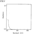
- an extracted solution obtained by extracting the toner with methanol has substantially no absorption peak in the range of 280 to 350 nm, and has a substantially zero absorbance in the range of 400 to 700 nm.
- the magnetic powder is contained in the range of 0.5 to 3 parts by weight per 100 parts by weight of the binder resin.
- the invention described herein makes possible the advantages of (1) providing toner with excellent chargeability including no charge control agent at all; (2) providing toner little scattered in development for realizing a copied image with a high quality; and (3) providing toner in which a spent is not caused even when used for a long period of time, and hence, by which an excellent image quality can be maintained and transfer efficiency can be stabilized.
- Toner for a two-component type developer accord ing to the present invention has no charge control agent, such as a dye of an azo compound - metal complex and an oxycarboxylic acid - metal complex, at all. Therefore, a spent caused by a charge control agent, which will be described in detail below, scarcely occurs in the present toner, resulting in realizing a high quality copied image for a long period of time. Since the toner of the present invention has no charge control agent, it is impossible to detect any charge control agent, i.e., a dye type compound, from the toner by any chemical or physical method. For example, such a compound cannot be detected in the present toner by any chemical reaction.
- absorption peaks owing to such a compound cannot be detected in an organic solvent extracted solution of the present toner.
- the present toner is extracted with an organic solvent such as methanol
- the extracted solution has substantially no absorption peak in the range of 280 to 350 nm, and has substantially zero absorbance in the range of 400 to 700 nm.
- “to have substantially no absorption peak” means, in an extracted solution obtained by extracting 0.1 g of the present toner with 50 ml of methanol, absorption peaks are not detected at all, or if detected, values of the absorbance peaks are 0.05 or less.
- “to have substantially zero absorbance” means that values of the absorbance of the extracted solution obtained by extracting 0.1 g of the present toner with 50 ml of methanol are 0.05 or less.
- the present toner instability of the charge of the toner due to a lack of a charge control agent is compensated for as follows.
- a polymer having an anionic group is used as a binder resin of a toner particle; and secondly, magnetic powder is contained in the toner particle at a predetermined proportion.
- two kinds of spacer particles having a predetermined resistivity and/or an attached stearic acid metallic salt are present. Therefore, chargeability of the toner is stabilized and the density of an image is improved.
- Figure 1 shows an UV-visible spectrum of a methanol extracted solution of the present toner in the range of 200 to 700 nm.
- the extracted solution has no peak, which is otherwise formed because of a charge control agent.
- the solution has substantially no absorption peak in the range of 280 to 350 nm, and the absorbance in the range of 400 to 700 nm is substantially zero.
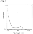
- absorption peaks are found in the range of 400 to 700 nm, in particular, 550 to 570 nm.
- an absorption peak is found in the range of 280 to 350 nm.
- the charge control agent is present on the surfaces of the toner particles at a rather high concentration that the methanol extracted solution of the toner having the charge control agent has absorption peaks due to the charge control agent.
- a carrier included in a developer which has insufficient chargeability owing to occurrence of a spent is extracted with methanol, and then the UV-visible spectrum of the extracted solution is measured to find absorption peaks in the range of 400 to 700 nm derived from a charge control agent.
- the developer comprising the toner having a dye of an azo compound - chrome complex, whose UV-visible spectrum is shown in Figure 2 was used for a long period of time to cause a spent therein.
- UV-visible spectrum of a methanol extracted solution of the carrier in this developer was measured to give the spectrum shown in Figure 4 .
- absorption peaks are found at the same position as the spectrum in Figure 2 .
- toner comprising toner particles containing 1.5 wt% of the dye of the azo compound - chrome complex was mixed with a carrier to obtain a developer.
- the toner and the carrier was shaken for a predetermined period of time.
- Figure 5 shows a relationship between the shaking time and amount of an attachment on the surfaces of the carrier particles.
- the amount of attachment is indicated as a spent ratio, that is, a percentage based on a total weight of the carrier particles bearing the attachment.
- Figure 6 shows the relationship between the shaking time and the amount of charge of the toner. The same procedure was repeated with regard to a developer comprising toner having no charge control agent and carrier.
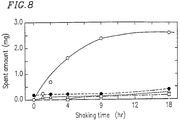
- the present inventors measured the weight of the attachment on the surfaces of the carrier particles resulting from mixing the carrier with each of the toner components, that is, a charge control agent, a binder resin, carbon black as a coloring agent and wax, so as to find out the relationships between the respective toner components and the spent.
- the results are shown in Figure 8 as a variation with time in the amount of the attachment (i.e., amount of the spent), wherein the results obtained from the mixture with the charge control agent is plotted with white circles, those from the carbon black with black circles, those from the binder resin with squares, and those from the wax with triangles. It is apparent from Figure 8 that the charge control agent causes the largest amount of attachment due to the spent.
- the toner does not have a charge control agent not only because the agent can include a heavy metal but also because the agent is the main cause of the spent, scatter of the toner and of a decrease in the transfer efficiency of the toner. Accordingly, the present toner has no charge control agent at all.
- the instability of charge of the toner due to the lack of the charge control agent, in particular, the insufficiency in charge amount of the toner is compensated by using a binder resin having an anionic group as mentioned above.
- the insufficiency in charge amount of the toner particles can be supplemented because the binder resin has a negative charge in itself owing to the anionic group included therein. Since the anionic group is bonded to the main chain of the binder resin, it would never move onto the surface of the carrier particle as the charge control agent does, and hence it never causes the spent.
- the present toner includes magnetic powder at a predetermined proportion, that is, 0.1 to 5 parts by weight on the basis of 100 parts by weight of the binder resin.
- the insufficiency in the charge amount of the toner particles can be thus compensated for.
- the magnetic powder contained in the toner particle causes magnetic attraction between the toner particle and the carrier particle. This magnetic attraction between the toner particle and the carrier particle together with electrostatic attraction prevents the toner from scattering.
- the number of the toner particles to be attached onto an electrostatic latent image is increased as the charge amount of one toner particle is smaller, apparent development sensitivity is increased.
- the content of the magnetic powder in the toner particles is in the range of 0.1 to 5 parts by weight per 100 parts by weight of the binder resin as described above.
- the content is less than 0.1 parts by weight, the charge amount of the toner particle is insufficient, resulting in insufficient coupling with the carrier particle and causing toner scattering. In this case, a fog can be disadvantageously formed on a copied image.
- the density of the copied image is low because of the insufficient charge amount.
- the contents exceeds 5 parts by weight the magnetic attraction between the carrier particle and the toner particle becomes so strong that the toner is not sufficiently attached onto an electrostatic latent image, resulting in decreasing the density of the copied image.
- Japanese Laid-Open Patent Publication No. 56-106249 discloses a toner particle including 10 wt% of ferrite
- Japanese Laid-Open Patent Publication No. 59-162563 discloses a toner particle including 5 through 35 wt% of a magnetic fine particle. In either case, however, the content of the magnetic powder is excessive, and hence, the density of the copied image is low.
- Japanese Laid-Open Patent Publication No. 3-67268 discloses toner to which 0.05 to 2 wt% of magnetic powder is externally added.
- the magnetic powder since the magnetic powder is not included in the toner particle, the powder is likely to be ununiformly attached onto the surface of the toner particle, resulting in insufficient magnetic attraction between the toner particle and the carrier particle. Furthermore, in either of the above-mentioned toners, the spent can be disadvantageously caused because a charge control agent is contained therein.
- spacer particles having a particle diameter of 0.05 through 1.0 ⁇ m are attached onto the surfaces of the toner particles in order to increase the transfer efficiency for a toner image.
- the spacer particles can work as a fluidity enhancer for the toner particles, and in addition, form a gap between the photosensitive body and the toner particles when the toner is attached onto an electrostatic latent image formed on the photosensitive body. Therefore, the toner can be transferred from the photosensitive body onto transfer paper with ease even when the toner attains a large charge amount due to a long copying operation, resulting in a high transfer efficiency.
- first spacer particles with a resistivity between 101 and 105 ⁇ cm, and second spacer particles with a resistivity between 108 and 1013 ⁇ cm are added to the present toner as the spacer particles.
- the transfer efficiency of the toner from the photosensitive body to transfer paper is improved.
- the surface of a toner particle is divided into two types of areas having different surface resistivity. As a result, these two types of areas work separately for charging and discharging the toner. Therefore, it is possible to attain a desired charge amount with ease. This results in improving the charge stability of the resultant toner and satisfactorily stabilizing the density of a copied image.
- fine particles having a particle diameter of approximately 0.015 ⁇ m are added as a fluidity enhancer in a conventional toner, such small particles cannot form a gap with a sufficient size between the photosensitive body and the toner particles. Therefore, they do not work as spacer particles for attaining the aforementioned purposes.
- a stearic acid metallic salt can be attached onto the surfaces of the toner particles and/or the spacer particles. This enhances the releasing property between the toner and the surface of the photosensitive body, and hence, the toner is unlikely to be attached onto the surface of the photosensitive body.
- the stearic acid metallic salt when selectively attached onto the surfaces of the spacer particles alone, the stearic acid metallic salt effectively comes in contact with the surface of the photosensitive body, thereby more effectively preventing the toner and the spacer particles from attaching onto the photosensitive body.
- the resistance of the toner is appropriately decreased, resulting in a copied image with a high density. Furthermore, since the melt viscosity of the toner is decreased by the stearic acid metallic salt, the toner can be well penetrated into transfer paper in the thermal fixing process by a heat roller, resulting in improving the fixability of a copied image onto the transfer paper. Moreover, since the melting temperature of the stearic acid metallic salt is lower than that of the binder resin, the surface of a copied image formed by fixing a transfer image is more smooth, resulting in the formation of a glossy copied image.
- a "lower alkyl group” indicates alkyl having 1 to 5 carbon atoms.
- the binder resin contained in the toner particles of the present toner comprises a composition including a polymer having an anionic group.
- a binder resin is obtained by polymerizing a monomer having an anionic group or a mixture of the monomer having an anionic group with other monomers.
- the obtained resin can be a homopolymer or a copolymer.
- the binder resin used in the present toner is preferably a copolymer, such as a random copolymer, a block copolymer and a grafted copolymer, obtained from a monomer having an anionic group and other monomers.
- Examples of the monomer having an anionic group include monomers having a carboxylic acid group, a sulfonic acid group or a phosphoric acid group, and a monomer having a carboxylic acid group is generally used.
- Examples of the monomer having a carboxylic acid group include ethylenically unsaturated carboxylic acids such as acrylic acid, methacrylic acid, crotonic acid, maleic acid and fumaric acid; monomers that can form a carboxylic acid group such as maleic anhydride; and lower alkyl halfester of dicarboxylic acid such as maleic acid and fumaric acid.
- Examples of the monomer having a sulfonicacid group include styrene sulfonic acid and 2-acrylamido-2-methylpropane sulfonic acid.
- Examples of the monomer having a phosphoric acid group include 2-phosphono(oxy)propylmethacrylate, 2-phosphono(oxy) ethylmethacrylate, 3-chloro-2-phosphono(oxy) propylmethacrylate.
- Such a monomer having an anionic group can be a free acid, a salt of an alkaline metal such as sodium and potassium, a salt of an alkaline earth metal such as calcium and magnesium, and a salt such as zinc.
- the monomer having no anionic group used to prepare the binder resin is selected so that the resultant binder resin has a sufficient fixability and chargeability required of toner, and is one or a combination of an ethylenically unsaturated monomer.
- a monomer include ethylenically unsaturated carboxylic acid ester, monovinyl arene, vinyl ester, vinyl ether, diolefin and monoolefin.
- the ethylenically unsaturated carboxylic acid esters are represented by the following Formula (I): wherein R1 is a hydrogen atom or a lower alkyl group; and R is a hydrocarbon group having 11 or less carbon atoms or a hydroxyalkyl group having 11 or less carbon atoms.
- Examples of such ethylenically unsaturated carboxylic acid esters include methyl acrylate, ethyl acrylate, butyl acrylate, 2-ethylhexyl acrylate, cyclohexyl acrylate, phenyl acrylate, methyl methacrylate, hexyl methacrylate, 2-ethylhexyl methacrylate, ⁇ -hydroxyethylacrylate, ⁇ -hydroxypropylacrylate, ⁇ -hydroxybutylacrylate and ⁇ -hydroxyethylmethacrylate.
- the monovinyl arenes are represented by the following Formula (II): wherein R3 is a hydrogen atom, a lower alkyl group or a halogen atom; R4 is a hydrogen atom, a lower alkyl group, a halogen atom, an alkoxy group, an amino group or a nitro group; and ⁇ is a phenylene group.
- Examples of such monovinyl arene include styrene, ⁇ -methylstyrene, vinyltoluene, ⁇ -chlorostyrene, o-chlorostyrene, m-chlorostyrene, p-chlorostyrene and p-ethylstyrene.
- the vinyl esters are represented by the following Formula (III): wherein R5 is a hydrogen atom or a lower alkyl group.
- vinyl esters examples include vinyl formate, vinyl acetate and vinyl propionate.
- vinyl ethers examples include vinyl methyl ether, vinyl ethyl ether, vinyl n-butyl ether, vinyl phenyl ether and vinyl cyclohexyl ether.
- the diolefins are represented by the following Formula (V): wherein R7, R8 and R9 are independently a hydrogen atom, a lower alkyl group or a halogen atom.
- diolefins examples include butadiene, isoprene and chloroprene.
- the monoolefins are represented by the following Formula (VI): wherein R10 and R11 are independently a hydrogen atom or a lower alkyl group.
- Examples of such monoolefins include ethylene, propylene, isobutylene, 1-butene, 1-pentene and 4-methyl-1-pentene.
- the polymer having an anionic group that is, a (co)polymer obtained through the polymerization of the aforementioned monomers, include styrene-acrylic acid copolymers, styrene-maleic acid copolymers and ionomer resins. Furthermore, a polyester resin having an anionic group can be also used.
- the polymer having an anionic group preferably includes the anionic group at a proportion for attaining an acid value of 2 through 30, and preferably 5 through 15, when the anionic group is present as a free acid. When part or the entire anionic group is neutralized, the anionic group is preferably contained at such a proportion that the acid value would be in the aforementioned range in assuming that it is present as a free acid.
- a preferable binder resin is a copolymer obtained from the monomer having an anionic group and at least one of the ethylenically unsaturated carboxylic acid ester represented by Formula (I) as an indispensable components, and any of the monomers represented by Formulae (II) through (VI) as an optional component to be used if necessary.
- One or a combination of two or more of the aforementioned monomers is used for preparing the binder resin.
- the composition can further comprise a polymer having no anionic group.
- the content of the anionic group in the entire composition is preferably within the aforementioned range.
- the magnetic powder contained in (inclusively added to) the toner particles can be any magnetic powder used in a conventional one-component type developer.
- the material for the magnetic powder include triiron tetroxide (Fe3O4), maghemite ( ⁇ -Fe2O3), zinc iron oxide (ZnFe2O4), yttrium iron oxide (Y3Fe5O12), cadmium iron oxide (CdFe2O4), gadolinium iron oxide (Gd3Fe5O12), copper iron oxide (CuFe2O4), lead iron oxide (PbFe12O19), nickel iron oxide (NiFe2O4), neodyum iron oxide (NdFeO3), barium iron oxide (BaFe12O19), magnesium iron oxide (MgFe2O4), manganese iron oxide (MnFe2O4), lanthanum iron oxide (LaFeO3), iron (Fe), cobalt (Co) and Nickel (Ni).
- Particularly preferable magnetic powder is made from triiron tetroxide (magnetite) in the shape of fine particles.
- the particle of preferable magnetite is in the shape of a regular octahedron with a particle diameter of 0.05 through 1.0 ⁇ m.
- Such a magnetite particle can be subjected to a surface treatment with a silane coupling agent or a titanium coupling agent.
- the particle diameter of the magnetic powder contained in the toner particle is generally 1.0 ⁇ m or smaller, and preferably in the range between 0.05 and 1.0 ⁇ m.
- the content of the magnetic powder in the toner particle is in the range of 0.1 to 5 parts by weight, more preferably 0.5 to 4 parts by weight, and most preferably 0.5 to 3 parts by weight per 100 parts by weight of the binder resin.
- the toner can be scattered during the development and the transfer efficiency of the toner can be decreased as described above.
- the toner particle contains, as described above, the binder resin and the magnetic powder as indispensable components, and can optionally include some inner additive generally used for a toner, if necessary.
- additives examples include a coloring agent and a release agent.
- the following pigments can be used:
- Such a pigment is contained in the toner particle in the range of 2 to 20 parts by weight, and preferably 5 to 15 parts by weight per 100 parts by weight of the binder resin.
- various wax and olefin resins can be used as in a conventional toner.
- the olefin resin include polypropylene, polyethylene, and propylene-ethylene copolymers, and polypropylene is particularly preferred.
- the toner particles in the present toner can be produced by any ordinary method for toner particles such as crushing and classification, fusing granulation, spray granulation and polymerization, and are generally produced by the crushing and classification method.
- the components for the toner particles are previously mixed in a mixer such as a Henschel mixer, kneaded with a kneader such as a biaxial extruder, and then cooled. The resultant is crushed and classified to give toner particles.
- the particle diameter of the toner particle is generally in the range between 5 and 15 ⁇ m and preferably between 7 and 12 ⁇ m in the volume-base averaged particle diameter (a medium size measured with a Coulter counter).
- the spacer particles are attached onto the surfaces of the toner particles to improve the transfer efficiency for a toner image.
- any of organic and inorganic inactive particles with a particle diameter of 0.05 through 1.0 ⁇ m, more preferably 0.07 through 0.5 ⁇ m can be used.
- material for such inactive particles include silica, alumina, titanium oxide, magnesium carbonate, an acrylic resin, a styrene resin and magnetic materials.
- the spacer particle can not only function as a fluidity enhancer but also increase the transfer efficiency as described above.
- the content of the spacer particles is 10 wt% or less, more preferably in the range between 0.1 and 10 wt%, and most preferably 0.1 and 5 wt% on the basis of the total weight of the toner.
- the spacer particles are excessively included, the concentration of a copied image is insufficient.
- two types of spacer particles with different resistivity as described below are attached onto the surfaces of the toner particles.
- first spacer particles organic or inorganic inactive particles with a volume-based average particle diameter of 0.05 through 1.0 ⁇ m, preferably 0.07 through 0.5 ⁇ m, and a resistivity between 101 and 105 ⁇ cm, preferably between 103 and 105 ⁇ cm, are used.
- material for such first spacer particles include titanium oxide and magnetite having been subjected to a surface treatment with a tin dope.
- organic or inorganic inactive particles with a volume-based average particle diameter of 0.05 through 1.0 ⁇ m, more preferably 0.07 through 0.5 ⁇ m, and a resistivity between 108 and 1013 ⁇ cm, more preferably between 109 and 101 ⁇ cm, are used.
- material for such second spacer particles include silica, alumina, titanium oxide, zinc oxide, barium sulfate, magnesium carbonate, an acrylic resin, a styrene resin and a styrene-acrylic copolymer.
- the resistivity of the spacer particle can be measured, for example, with a resistivity measuring device 4 having a structure as is shown in Figure 11 .
- the measuring method with the resistivity measuring device 4 will now be described.
- 8 g of spacer particles 203 are put in a tube 41 made of vinyl chloride having an inner diameter H1 of 1 inch, and being sandwiched between steel electrodes 421 .
- the outer surfaces of the electrodes 421 are provided with Teflon plates 43 with a thickness of 2 mm.
- the total content of the spacer particles is 10 wt% or less, preferably in the range between 0.1 and 10 wt%, and most preferably between 0.1 and 5 wt% based on the total weight of the resultant toner. When they are excessively included, the density of a copied image is insufficient.
- the weight ratio of the first spacer particles to the second spacer particles contained in the present toner is not herein specifically limited, the weight ratio is preferably in the range from 1:7 to 7:1, and more preferably from 1:4 to 4:1.
- these spacer particles are contained at such a ratio, it is possible to have the surface of a toner particle to work separately for charging and discharging the toner, thereby enhancing the effect to attain a desired charge amount.
- Examples of a stearic acid metallic salt which can be added to the toner particles bearing the aforementioned spacer particles, include zinc stearate, magnesium stearate, aluminum stearate, potassium stearate, chromium stearate, mercury stearate, cerium stearate, iron (II) stearate, sodium stearate, lead stearate and barium stearate.
- a stearic acid metallic salt can be replaced with amide stearate.
- the stearic acid metallic salt can be added to the toner particles bearing the spacer particles in the range of 0.001 to 3 wt%, preferably 0.003 to 1 wt%, and most preferably 0.005 to 0.2 wt% based on the total weight of the toner.
- the stearic acid metallic salt can be attached onto the surfaces of both the toner particles and the spacer particles. It is preferable, however, that the stearic acid metallic salt is attached selectively onto the surfaces of the spacer particles attached onto the toner particles.
- "To be attached selectively onto the surfaces of the spacer particles" herein means that the stearic acid metallic salt is not substantially attached onto the surface of a toner particle but attached onto the surface of a spacer particle alone.
- the stearic acid metallic salt is previously mixed with the spacer particles, and the resultant mixture is then added to the toner particles as described below.
- the present toner includes, as described above, the spacer particles with a predetermined particle diameter on the surfaces of the toner particles.
- the spacer particles can be two types with different resistivity, or the stearic acid metallic salt can be attached onto the surfaces of the toner particles and/or the spacer particles. It is possible to further improve the fluidity of the resultant toner by attaching a fluidity enhancer, other than the stearic acid metallic salt, having a smaller particle diameter than that of the spacer particles, such as hydrophobic vapor depositioned silica particles.
- the primary particle diameter of the fluidity enhancer such as the silica particles is generally approximately 0.015 ⁇ m.
- the fluidity enhancer can be added to the toner in an amount of 0.1 to 2.0 wt% based on the weight of the entire toner, i.e., the total weight of the toner particles and the additives (such as the spacer particles and the fluidity enhancer).
- the spacer particles preferably, the two types of spacer particles
- a stearic acid metallic salt, a fluidity enhancer and the like if necessary, are sufficiently mixed.
- the obtained mixture is added to the toner particles, and the resultant is sufficiently unbound.
- the spacer particles can be uniformly attached onto the surfaces of the toner particles.
- the stearic acid metallic salt is added into this manner, the stearic acid metallic salt is attached onto the surfaces of both the toner particles and the spacer particles.
- the toner particles are previously sufficiently mixed with a stearic acid metallic salt. Then, the spacer particles, and a fluidity enhancer, if necessary, are attached onto the surfaces of the toner particles already bearing the stearic acid metallic salt. Thus, in the resultant toner, the stearic acid metallic salt is not attached onto the surfaces of the spacer particles but onto the surfaces of the toner particles alone.
- To “be attached” herein means both to be held in contact with the surface of a particle and to be partly embedded in the particle.
- the present toner is prepared.
- generally used magnetite or ferrite can be used as a carrier for the two-component type developer.
- the electrical resistance is stable and varies very little with time or by the change of the environment, and hence, it can provide the resultant developer with a stable chargeability.
- such a compound is formed into a soft spicated shape in the developing apparatus when a magnetic field is applied. This prevents the turbulence of a toner image formed on the photosensitive body, thereby suppressing the formation of a white stripe in a copied image.
- the ferrite can be preferably used.
- the carrier particle in the carrier used in the present invention is more preferably formed from a particle having a two-layered structure including a core particle and a coating layer over the core particle.
- the core particle comprises a magnetic material represented by the following Formula (A): MOFe2O3 (A) wherein M is at least one metal selected from the group consisting of Cu, Zn, Fe, Ba, Ni, Mg, Mn, Al and Co.
- the compound represented by Formula (A) is magnetite (wherein M is Fe) or ferrite (wherein M is one of the metals other than Fe), and ferrite, wherein M is Cu, Zn, Mn, Ni or Mg, is preferably used. Change of the electrical resistance of such magnetite and ferrite is little for a long time, and the magnetite and ferrite can be formed into a soft spicated shape in the developing apparatus when a magnetic field is applied.
- the core particle comprising such a magnetic material has a particle diameter between 30 and 200 ⁇ m, and preferably between 50 and 150 ⁇ m.
- the core particles are obtained by granulating the fine particles of the magnetic material by spray granulation and the like, and then heating the resultant particles.
- the core particle has a volume specific resistivity between 105 and 109 ⁇ cm, and preferably between 106 and 108 ⁇ cm.
- the saturation magnetization of the core particle is in the range of 30 to 70 emu/g, and preferably between 45 and 65 emu/g.
- the resin having a cationic group included in the resin composition, which forms the coating layer of the carrier particle can be a thermoplastic resin and a thermosetting resin, and is preferably a thermosetting resin or a mixture of a thermosetting resin and a thermoplastic resin in terms of the heat resistance and the durability.
- the cationic group include a basic nitrogen containing group such as primary, secondary and tertiary amino groups, a quaternary ammonium group, an amido group, an imino group, an imido group, a hydrazino group, a guanidino group and an amidino group, among which an amino group and a quaternary ammonium group are particularly preferred.
- thermoplastic resin having a cationic group examples include thermoplastic acrylic resins, thermoplastic styrene-acrylic resins, polyester resins, polyamide resins and olefin copolymer, each of which includes a cationic group.
- thermosetting resin examples include modified and unmodified silicone resins, thermosetting acrylic resins, thermosetting styreneacrylic resins, phenol resins, urethane resins, thermosetting polyester resins, epoxy resins and amino resins, each of which includes a cationic group.
- Such a resin including a cationic group is obtained by polymerizing a monomer having a cationic group or a mixture containing the monomer having a cationic group.
- such a resin is obtained by linking a compound having a cationic group with a resin having no cationic group.
- a monomer having a cationic group and/or another monomer are (co)polymerized by using a polymerization initiator having a cationic group, thereby introducing the cationic group into the resultant resin.
- the resin having a cationic group When a resin prepared from alkoxysilane or alkoxytitanium is used, it is possible to produce the resin having a cationic group by allowing a silane coupling agent having a cationic group to react with the resin during or after the preparation of the resin.
- the silane coupling agent include N-(2-aminoethyl)-3-aminopropyltrimethoxysilane, N-(2-aminoethyl)-3-aminopropylmethyldimethoxysilane, ⁇ -aminopropyltriethoxysilane and N-phenyl-3-aminopropyltrimethoxysilane.
- silane coupling agent can be linked onto the surface of the core particle via a hydroxyl group generally present on the surface of the core particle. Therefore, such a silane coupling agent can form the coating layer by itself.
- the polymerization initiator having a cationic group include amidine type compound, e.g., azobis compounds.
- the resin having a cationic group for forming the coating layer is used singly or together with any other of the aforementioned resins, or together with another resin having no cationic group.
- the content of the cationic group in the resin having a cationic group is generally in the range of 0.1 to 2000 mmole, and preferably of 0.5 to 1,500 mmole per 100 g of the resin.
- the cationic group is preferably contained in the entire resins forming the coating layer of the carrier particle at a proportion in the aforementioned range.
- the resin composition forming the coating layer of the carrier particle includes at least one of the above-mentioned resins having a cationic group, together with another resin having no cationic group, if necessary.
- a mixture of the resin having a cationic group and the resin having no cationic group include a mixture of an alkylated melamine resin and a styrene-acrylic copolymer, and a mixture of an alkylated melamine resin and an acryl-modified silicone resin.
- the resin composition can further comprise an additive such as silica, alumina, carbon black, fatty acid metal salt, a silane coupling agent and silicone oil. These additives work for regulating physical properties of the coating layer.
- the resin composition including a cationic group is applied to the surface of the core particle by a known method to form the coating layer.
- the core particle is coated with a solution or a dispersion of the resin composition and dried, thereby forming the coating layer.
- the core particle is coated with an uncured resin, or a solution or a dispersion of the oligomer, and then heated to cure the resin.
- the coating layer can be formed by any of the generally used methods such as immersion, spray, a fluidized bed method, a moving bed method and a tumbling layer method.
- a solvent used to dissolve or disperse the resin composition any of the ordinary organic solvents can be used.
- the solvent examples include aromatic hydrocarbons such as toluene and xylene; ketones such as acetone, methyl ethyl ketone, methyl isobutyl ketone and cyclohexanone; cyclic ethers such as tetrahydrofuran and dioxane; alcohols such as ethanol, propanol and butanol; cellosolves such as ethyl cellosolve and butyl cellosolve; esters such as ethyl acetate and butyl acetate; and amide type solvents such as dimethylformamide and dimethylacetoamide.
- aromatic hydrocarbons such as toluene and xylene
- ketones such as acetone, methyl ethyl ketone, methyl isobutyl ketone and cyclohexanone
- cyclic ethers such as tetrahydrofuran and dioxane
- alcohols such as ethanol, prop
- the particle diameter of the thus obtained carrier particle is in the range of 30 to 200 ⁇ m, and preferably 50 to 150 ⁇ m.
- the weight ratio of the coating layer on the carrier particle is in the range of 0.001 to 2.5 parts by weight, and preferably 0.005 to 2.0 parts by weight per 100 parts by weight of the core particle.
- the obtained carrier particle has a volume specific resistivity in the range between 105 and 1013 ⁇ cm, and preferably 107 and 101 ⁇ cm, and a saturation magnetization in the range between 30 and 70 emu/g, and preferably 45 and 65 emu/g.
- a two-component type developer is prepared by mixing the above-mentioned toner and carrier.
- the mixing ratio of the carrier and the toner is generally 98:2 through 90:10, and preferably 97:3 through 94:6, by weight.
- a copying operation is conducted using the present toner by a general electrophotographic method. Specifically, for example, a photoconductive layer on a photosensitive body is uniformly charged, and an image is exposed to form an electrostatic latent image thereon. Then, a magnetic brush made of the two-component magnetic developer is allowed to come in contact with the photosensitive body, thereby developing the electrostatic latent image with ease into a toner image. The thus obtained toner image is transferred onto transfer paper to form a transfer image, which is then applied with heat and pressure by a heat roller to fix the image thereon.
- toner particles were added 0.3 parts by weight of hydrophobic silica fine powder with an average particle diameter of 0.015 ⁇ m as a fluidity enhancer and 0.5 parts by weight of acrylic resin particles with an average particle diameter of 0.15 ⁇ m as spacer particles, on the basis of 100 parts by weight of the toner particles.
- the thus obtained toner and a ferrite carrier with an average particle diameter of 100 ⁇ m were homogeneously mixed to give a two-component type developer having a toner concentration of 3.5 wt%.
- Example 1.1 The same procedure was repeated as in Example 1.1 except that magnetite particles with an average particle diameter of 0.4 ⁇ m were added as the spacer particles, thereby preparing a developer.
- Example 1.1 The same procedure was repeated as in Example 1.1 except that no spacer particles were used, thereby preparing a developer.
- toner particles were added 0.3 parts by weight of hydrophobic silica fine powder with an average particle diameter of 0.015 ⁇ m as a fluidity enhancer on the basis of 100 parts by weight of the toner particles.
- titanium oxide particles having been subjected to a surface treatment by a tin dope and having a volume-based average particle diameter of 0.3 ⁇ m and resistivity of 2 x 10³ ⁇ cm were added as the first spacer particles at a proportion of 0.5 part by weight
- alumina particles having a volume-based average particle diameter of 0.3 ⁇ m and resistivity of 1010 ⁇ cm were added as the second spacer particles at a proportion of 0.5 parts by weight, on the basis of 100 parts by weight of the toner particles.
- the resultant mixture was mixed with a Henschel mixer for 2 minutes to give toner including the toner particles on which the aforementioned particles were attached.
- the thus obtained toner and a ferrite carrier with an average particle diameter of 100 ⁇ m were homogeneously mixed to give a two-component type developer having a toner concentration of 3.5 wt%.
- Example 2.1 The same procedure was repeated as in Example 2.1 except that the first spacer particles were added at a proportion of 1 part by weight on the basis of 100 parts by weight of the toner particles and that the second spacer particles were not added, thereby preparing a developer.
- Example 2.1 The same procedure was repeated as in Example 2.1 except that the second spacer particles were added at a proportion of 1 part by weight on the basis of 100 parts by weight of the toner particles and that the first spacer particles were not added, thereby preparing a developer.
- Example 2.1 The same procedure was repeated as in Example 2.1 except that the first and second spacer particles were not added, and that titanium oxide particles having a volume-based average particle diameter of 0.3 ⁇ m and resistivity of 106 ⁇ cm were added at a proportion of 1 part by weight on the basis of 100 parts by weight of the toner particles, thereby preparing a developer.
- Toner was prepared in the same manner as in Example 2.1.
- Spherical ferrite particles with an average particle diameter of 100 ⁇ m were used as the magnetic core particles.
- a coating agent with components as listed in Table 1 was added to 1000 parts by weight of the ferrite particles, and the resultant was mixed with a thermal stirrer. The solvent was removed from the resultant mixture, and the residue was subjected to a heat treatment at a temperature of 200°C for 1 hour to give carrier particles each having a coating layer.
- the thus obtained toner and carrier were homogeneously mixed to give a two-component type developer having a toner concentration of 3.5 wt%.
- Example 3.1 The same procedure was repeated as in Example 3.1 except that the components of a used coating agent were as listed in Table 1, thereby preparing a developer.
- Example 3.1 The same procedure was repeated as in Example 3.1 except that the components of a used coating agent were as listed in Table 1, thereby preparing a developer.
- Example 3.1 The same procedure was repeated as in Example 3.1 except that a coating layer was not formed without using any coating agent, thereby preparing a developer.
- toner particles were added 0.3 parts by weight of hydrophobic silica fine powder with an average particle diameter of 0.015 ⁇ m as a fluidity enhancer, and 0.5 parts by weight of magnesium carbonate particles with an average particle diameter of 0.15 ⁇ m as spacer particles, on the basis of 100 parts by weight of the toner particles. Further, zinc stearate was added as the stearic acid metallic salt at a proportion of 0.05 parts by weight based on 100 parts by weight of the toner particles. The resultant mixture was mixed with a Henschel mixer for 2 minutes to give toner.
- the thus obtained toner and a ferrite carrier with an average particle diameter of 100 ⁇ m were homogeneously mixed to give a two-component type developer having a toner concentration of 3.5 wt%.
- the resultant mixture was added to the toner particles prepared in Example 4.1 at a proportion of 0.55 part by weight (i.e., 0.5 part by weight of magnesium carbonate and 0.05 part by weight of zinc stearate) on the basis of 100 parts by weight of the toner particles. Further, hydrophobic silica fine particles with an average particle diameter of 0.015 ⁇ m were added as a fluidity enhancer at a proportion of 0.3 part by weight on the basis of 100 parts by weight of the toner particles. The resultant mixture was mixed with a Henschel mixer for 2 minutes to give toner.
- the thus obtained toner and a ferrite carrier with an average particle diameter of 100 ⁇ m were homogeneously mixed to give a two-component type developer having a toner concentration of 3.5 wt%.
- Example 4.2 The same procedure was repeated as in Example 4.2 except that 1 part by weight of zinc stearate was replaced with 2 parts by weight of magnesium stearate, and that the mixture of magnesium carbonate and magnesium stearate was added to the toner particles at a proportion of 0.52 parts by weight (i.e., 0.5 parts by weight of magnesium carbonate and 0.02 parts by weight of magnesium stearate), thereby preparing toner.
- the thus obtained toner and a ferrite carrier with an average particle diameter of 100 ⁇ m were homogeneously mixed to give a two-component type developer having a toner concentration of 3.5 wt%.
- Example 4.1 The same procedure was repeated as in Example 4.1 except that zinc stearate was not added, thereby preparing a developer.
- Toner was prepared in the same manner as in Example 4.1.
- Spherical ferrite particles with an average particle diameter of 100 ⁇ m were used as the magnetic core particles.
- a coating agent with components as listed in Table 2 was added to 1000 parts by weight of the ferrite particles.
- the solvent was removed from the resultant mixture, and the residue was subjected to a heat treatment at a temperature of 200°C for 1 hour to give carrier particles each having a coating layer.
- the thus obtained toner and carrier were homogeneously mixed to give a two-component type developer having a toner concentration of 3.5 wt%.
- Example 5.1 The same procedure was repeated as in Example 5.1 except that the components of a used coating agent were as listed in Table 2, thereby preparing a developer.
- Example 5.1 The same procedure was repeated as in Example 5.1 except that the components of a used coating agent were as listed in Table 2, thereby preparing a developer.
- Example 5.1 The same procedure was repeated as in Example 5.1 except that a coating layer was not formed without using any coating agent, thereby preparing a developer.
- Table 2 Coating Agent of Examples 5.1-5.4 component Example 5.1
- Example 5.2 Example 5.3
- Resin 1 Acryl-modified silicone Metylphenyl silicone Styrene-acrylic polymer none parts by weight 2.5 4.8 3.5
- Resin 2 Metylated melamine ⁇ -aminoproyltriethoxysilane Methylated melamine none parts by weight 2.5 0.2 1.5
- Toner was prepared in the same manner as in Example 4.2.
- Spherical ferrite particles with an average particle diameter of 100 ⁇ m were used as the magnetic core particles.
- a coating agent with components as listed in Table 3 was added to 1000 parts by weight of the ferrite particles.
- the solvent was removed from the resultant mixture, and the residue was subjected to a heat treatment at a temperature of 200°C for 1 hour to give carrier particles each having a coating layer.
- the thus obtained toner and carrier were homogeneously mixed to give a two-component type developer having a toner concentration of 3.5 wt%.
- Example 6.1 The same procedure was repeated as in Example 6.1 except that the components of a used coating agent were as listed in Table 3, thereby preparing a developer.
- Example 6.1 The same procedure was repeated as in Example 6.1 except that the components of a used coating agent were as listed in Table 3, thereby preparing a developer.
- Example 6.1 Example 6.1
- Example 6.2 Example 6.3
- Example 6.4 Resin 1 Acryl-modified silicone Metylphenyl silicone Styrene-acrylic polymer none parts by weight 2.5 4.8 3.5
- Resin 2 Metylated melamine ⁇ -aminopropyltriethoxysilane Methylated melamine none parts by weight 2.5 0.2 1.5
- the developers produced in Examples 1.1 and 1.2 were more stable in the charge amount and had a smaller spent amount, a lower fog density and higher transfer efficiency as compared with the developer having no spacer particles produced in Comparative Example 1.
- the developers produced in Examples 2.2 through 2.4 containing the toner including one kind of desired spacer particles were excellent in the fog density, prevention of the toner scattering, the transfer efficiency and the charge stability.
- the developer produced in Example 2.1 containing the toner including the two kinds of spacer particles was further improved in the transfer efficiency and the charge stability.
- Example 3.4 including the carrier having no coating layer was excellent in the fog density, the charge amount and prevention of the toner scattering, the developers produced in Examples 3.1 through 3.3 including the carrier having a coating layer had a further smaller spent amount and a further higher durability.
- Example 4.4 including the toner having no stearic acid metallic salt was excellent in the fog density, prevention of the toner scattering, the charge amount and the anti-spent property
- the developers produced in Examples 4.1 through 4.3 including the toner having a stearic acid metallic salt were further improved in suppressing appearance of a white dot in a black solid portion.
Applications Claiming Priority (4)
| Application Number | Priority Date | Filing Date | Title |
|---|---|---|---|
| JP207443/94 | 1994-08-31 | ||
| JP6207443A JPH0876418A (ja) | 1994-08-31 | 1994-08-31 | 二成分系現像剤用トナー |
| JP6207446A JPH0876421A (ja) | 1994-08-31 | 1994-08-31 | 二成分系現像剤用トナー |
| JP207446/94 | 1994-08-31 |
Publications (1)
| Publication Number | Publication Date |
|---|---|
| EP0703503A1 true EP0703503A1 (de) | 1996-03-27 |
Family
ID=26516252
Family Applications (1)
| Application Number | Title | Priority Date | Filing Date |
|---|---|---|---|
| EP95305607A Withdrawn EP0703503A1 (de) | 1994-08-31 | 1995-08-11 | Toner für Zweikomponentenentwickler |
Country Status (3)
| Country | Link |
|---|---|
| EP (1) | EP0703503A1 (de) |
| KR (1) | KR960008442A (de) |
| CN (1) | CN1140267A (de) |
Cited By (3)
| Publication number | Priority date | Publication date | Assignee | Title |
|---|---|---|---|---|
| EP0813118A2 (de) * | 1996-06-10 | 1997-12-17 | Mita Industrial Co. Ltd. | Toner für Zweikomponentenentwickler |
| EP0898205A1 (de) * | 1997-08-21 | 1999-02-24 | Brother Kogyo Kabushiki Kaisha | Toner |
| EP1589381A2 (de) * | 2004-04-20 | 2005-10-26 | Tomoegawa Paper Co. Ltd. | Elektrophotographische harzbeschichtete Trägerteilchen und Zwei-Komponenten Entwickler |
Families Citing this family (2)
| Publication number | Priority date | Publication date | Assignee | Title |
|---|---|---|---|---|
| KR100491607B1 (ko) * | 2002-02-18 | 2005-05-27 | 삼성전자주식회사 | 정전잠상 현상용 비접촉 비자성 1성분계 토너 및 그것을사용하는 현상장치 |
| US7312010B2 (en) * | 2005-03-31 | 2007-12-25 | Xerox Corporation | Particle external surface additive compositions |
Citations (7)
| Publication number | Priority date | Publication date | Assignee | Title |
|---|---|---|---|---|
| JPS56106249A (en) | 1980-01-28 | 1981-08-24 | Fujitsu Ltd | Developer |
| JPS59162563A (ja) | 1983-03-07 | 1984-09-13 | Minolta Camera Co Ltd | 静電潜像現像用磁性現像剤 |
| EP0330287A2 (de) * | 1988-02-26 | 1989-08-30 | Mita Industrial Co., Ltd. | Toner für die Entwicklung statischer Ladungsbilder und Verfahren zu dessen Herstellung |
| EP0357042A2 (de) * | 1988-08-30 | 1990-03-07 | TDK Corporation | Zusammensetzung und Verfahren für die Entwicklung latenter elektrostatischer Bilder |
| JPH0367268A (ja) | 1989-03-28 | 1991-03-22 | Hitachi Chem Co Ltd | 乾式トナー,乾式現像剤及び画像形成方法 |
| JPH064950A (ja) * | 1992-06-22 | 1994-01-14 | Sharp Corp | 音響機器におけるカセット収納機構 |
| EP0643337A1 (de) * | 1993-08-19 | 1995-03-15 | Mita Industrial Co., Ltd. | Toner für ein zwei-komponenten-Typ magnetisches Entwicklungsagenz mit excellentem "Spent"-Widerstand |
-
1995
- 1995-08-11 EP EP95305607A patent/EP0703503A1/de not_active Withdrawn
- 1995-08-30 KR KR1019950027434A patent/KR960008442A/ko not_active Application Discontinuation
- 1995-08-31 CN CN95115391A patent/CN1140267A/zh active Pending
Patent Citations (7)
| Publication number | Priority date | Publication date | Assignee | Title |
|---|---|---|---|---|
| JPS56106249A (en) | 1980-01-28 | 1981-08-24 | Fujitsu Ltd | Developer |
| JPS59162563A (ja) | 1983-03-07 | 1984-09-13 | Minolta Camera Co Ltd | 静電潜像現像用磁性現像剤 |
| EP0330287A2 (de) * | 1988-02-26 | 1989-08-30 | Mita Industrial Co., Ltd. | Toner für die Entwicklung statischer Ladungsbilder und Verfahren zu dessen Herstellung |
| EP0357042A2 (de) * | 1988-08-30 | 1990-03-07 | TDK Corporation | Zusammensetzung und Verfahren für die Entwicklung latenter elektrostatischer Bilder |
| JPH0367268A (ja) | 1989-03-28 | 1991-03-22 | Hitachi Chem Co Ltd | 乾式トナー,乾式現像剤及び画像形成方法 |
| JPH064950A (ja) * | 1992-06-22 | 1994-01-14 | Sharp Corp | 音響機器におけるカセット収納機構 |
| EP0643337A1 (de) * | 1993-08-19 | 1995-03-15 | Mita Industrial Co., Ltd. | Toner für ein zwei-komponenten-Typ magnetisches Entwicklungsagenz mit excellentem "Spent"-Widerstand |
Non-Patent Citations (1)
| Title |
|---|
| PATENT ABSTRACTS OF JAPAN vol. 9, no. 120 (P - 358)<1843> 24 May 1985 (1985-05-24) * |
Cited By (7)
| Publication number | Priority date | Publication date | Assignee | Title |
|---|---|---|---|---|
| EP0813118A2 (de) * | 1996-06-10 | 1997-12-17 | Mita Industrial Co. Ltd. | Toner für Zweikomponentenentwickler |
| EP0813118A3 (de) * | 1996-06-10 | 1998-01-07 | Mita Industrial Co. Ltd. | Toner für Zweikomponentenentwickler |
| EP0898205A1 (de) * | 1997-08-21 | 1999-02-24 | Brother Kogyo Kabushiki Kaisha | Toner |
| US6054239A (en) * | 1997-08-21 | 2000-04-25 | Brother Kogyo Kabushiki Kaisha | Toner |
| EP1589381A2 (de) * | 2004-04-20 | 2005-10-26 | Tomoegawa Paper Co. Ltd. | Elektrophotographische harzbeschichtete Trägerteilchen und Zwei-Komponenten Entwickler |
| EP1589381A3 (de) * | 2004-04-20 | 2006-09-06 | Tomoegawa Paper Co. Ltd. | Elektrophotographische harzbeschichtete Trägerteilchen und Zwei-Komponenten Entwickler |
| US7682764B2 (en) | 2004-04-20 | 2010-03-23 | Tomoegawa Paper Co., Ltd | Resin coated carrier for electrophotography and two-component developer for electrophotography made therefrom |
Also Published As
| Publication number | Publication date |
|---|---|
| KR960008442A (ko) | 1996-03-22 |
| CN1140267A (zh) | 1997-01-15 |
Similar Documents
| Publication | Publication Date | Title |
|---|---|---|
| EP0703505B1 (de) | Toner für Zweikomponentenentwickler | |
| EP0703503A1 (de) | Toner für Zweikomponentenentwickler | |
| EP0704767A1 (de) | Entwickler des Zweikomponententyps | |
| EP0703504B1 (de) | Toner für Zweikomponentenentwickler | |
| EP0704768A1 (de) | Toner für Zweikomponentenentwickler | |
| JPH0876436A (ja) | 二成分系現像剤 | |
| JPH0876444A (ja) | 二成分系現像剤 | |
| JPH0876511A (ja) | 二成分系現像剤 | |
| JPH0876428A (ja) | 二成分系現像剤 | |
| JPH0876435A (ja) | 二成分系現像剤 | |
| JPH0876430A (ja) | 二成分系現像剤 | |
| JPH0876432A (ja) | 二成分系現像剤 | |
| JPH0876425A (ja) | 二成分系現像剤 | |
| JPH0876427A (ja) | 二成分系現像剤 | |
| JPH0876429A (ja) | 二成分系現像剤 | |
| JPH0876446A (ja) | 二成分系現像剤 | |
| JPH0876422A (ja) | 二成分系現像剤 | |
| JPH0876421A (ja) | 二成分系現像剤用トナー | |
| JPH0876474A (ja) | 二成分系現像剤 | |
| JPH0876424A (ja) | 二成分系現像剤 | |
| JPH0876431A (ja) | 二成分系現像剤 | |
| JPH0876433A (ja) | 二成分系現像剤 | |
| JPH0876426A (ja) | 二成分系現像剤 | |
| JPH0876489A (ja) | 二成分系現像剤 | |
| JPH0876438A (ja) | 二成分系現像剤 |
Legal Events
| Date | Code | Title | Description |
|---|---|---|---|
| PUAI | Public reference made under article 153(3) epc to a published international application that has entered the european phase |
Free format text: ORIGINAL CODE: 0009012 |
|
| AK | Designated contracting states |
Kind code of ref document: A1 Designated state(s): CH DE ES FR GB IT LI |
|
| 17P | Request for examination filed |
Effective date: 19960923 |
|
| 17Q | First examination report despatched |
Effective date: 19980115 |
|
| STAA | Information on the status of an ep patent application or granted ep patent |
Free format text: STATUS: THE APPLICATION IS DEEMED TO BE WITHDRAWN |
|
| 18D | Application deemed to be withdrawn |
Effective date: 19980526 |