EP0703431A2 - Dispositif de saisi de processus de mouvement - Google Patents
Dispositif de saisi de processus de mouvement Download PDFInfo
- Publication number
- EP0703431A2 EP0703431A2 EP95250233A EP95250233A EP0703431A2 EP 0703431 A2 EP0703431 A2 EP 0703431A2 EP 95250233 A EP95250233 A EP 95250233A EP 95250233 A EP95250233 A EP 95250233A EP 0703431 A2 EP0703431 A2 EP 0703431A2
- Authority
- EP
- European Patent Office
- Prior art keywords
- signals
- speed
- evaluation
- signal
- unit
- Prior art date
- Legal status (The legal status is an assumption and is not a legal conclusion. Google has not performed a legal analysis and makes no representation as to the accuracy of the status listed.)
- Withdrawn
Links
Images


Classifications
-
- G—PHYSICS
- G07—CHECKING-DEVICES
- G07C—TIME OR ATTENDANCE REGISTERS; REGISTERING OR INDICATING THE WORKING OF MACHINES; GENERATING RANDOM NUMBERS; VOTING OR LOTTERY APPARATUS; ARRANGEMENTS, SYSTEMS OR APPARATUS FOR CHECKING NOT PROVIDED FOR ELSEWHERE
- G07C5/00—Registering or indicating the working of vehicles
- G07C5/08—Registering or indicating performance data other than driving, working, idle, or waiting time, with or without registering driving, working, idle or waiting time
- G07C5/0841—Registering performance data
- G07C5/085—Registering performance data using electronic data carriers
-
- G—PHYSICS
- G01—MEASURING; TESTING
- G01C—MEASURING DISTANCES, LEVELS OR BEARINGS; SURVEYING; NAVIGATION; GYROSCOPIC INSTRUMENTS; PHOTOGRAMMETRY OR VIDEOGRAMMETRY
- G01C21/00—Navigation; Navigational instruments not provided for in groups G01C1/00 - G01C19/00
- G01C21/10—Navigation; Navigational instruments not provided for in groups G01C1/00 - G01C19/00 by using measurements of speed or acceleration
- G01C21/12—Navigation; Navigational instruments not provided for in groups G01C1/00 - G01C19/00 by using measurements of speed or acceleration executed aboard the object being navigated; Dead reckoning
- G01C21/16—Navigation; Navigational instruments not provided for in groups G01C1/00 - G01C19/00 by using measurements of speed or acceleration executed aboard the object being navigated; Dead reckoning by integrating acceleration or speed, i.e. inertial navigation
- G01C21/183—Compensation of inertial measurements, e.g. for temperature effects
- G01C21/188—Compensation of inertial measurements, e.g. for temperature effects for accumulated errors, e.g. by coupling inertial systems with absolute positioning systems
-
- G—PHYSICS
- G01—MEASURING; TESTING
- G01P—MEASURING LINEAR OR ANGULAR SPEED, ACCELERATION, DECELERATION, OR SHOCK; INDICATING PRESENCE, ABSENCE, OR DIRECTION, OF MOVEMENT
- G01P1/00—Details of instruments
- G01P1/07—Indicating devices, e.g. for remote indication
-
- G—PHYSICS
- G01—MEASURING; TESTING
- G01P—MEASURING LINEAR OR ANGULAR SPEED, ACCELERATION, DECELERATION, OR SHOCK; INDICATING PRESENCE, ABSENCE, OR DIRECTION, OF MOVEMENT
- G01P1/00—Details of instruments
- G01P1/12—Recording devices
- G01P1/122—Speed recorders
-
- G—PHYSICS
- G01—MEASURING; TESTING
- G01P—MEASURING LINEAR OR ANGULAR SPEED, ACCELERATION, DECELERATION, OR SHOCK; INDICATING PRESENCE, ABSENCE, OR DIRECTION, OF MOVEMENT
- G01P15/00—Measuring acceleration; Measuring deceleration; Measuring shock, i.e. sudden change of acceleration
- G01P15/02—Measuring acceleration; Measuring deceleration; Measuring shock, i.e. sudden change of acceleration by making use of inertia forces using solid seismic masses
- G01P15/08—Measuring acceleration; Measuring deceleration; Measuring shock, i.e. sudden change of acceleration by making use of inertia forces using solid seismic masses with conversion into electric or magnetic values
-
- G—PHYSICS
- G01—MEASURING; TESTING
- G01P—MEASURING LINEAR OR ANGULAR SPEED, ACCELERATION, DECELERATION, OR SHOCK; INDICATING PRESENCE, ABSENCE, OR DIRECTION, OF MOVEMENT
- G01P7/00—Measuring speed by integrating acceleration
Definitions
- the invention relates to a device of the type specified in the preamble of claim 1 and a method for operating such a device.
- the signal transmitters the output signals of which are included in the determination or recording of the speed of travel, or their connection points with the evaluation and recording unit, are particularly vulnerable to manipulation. Tampering with the encoder, with which its impulses are faked with the aim of simulating a speed lower than the actual speed, is common, and even the replacement of pulse sources instead of the calibrated encoder has already occurred.
- DE 40 22 312 A1 describes a system and a recording device for analyzing vehicle movement data, which has a number of additional sensors for recording additional driving physical data. This is intended to increase the number of external conditions data relating to the driving process and possibly relevant in the event of an accident. With regard to the manipulation problem, this document does not make any statements.
- DE 38 39 221 describes a driving data memory which works digitally and whose stored data are transmitted in encrypted form to the outside of the vehicle for external, computer-aided evaluation. This is intended to prevent tampering in the area of data recording and storage, but the solution is not suitable for preventing tampering with the signal transmitters.
- a generic device is known from EP 0 322 532. Correction of the accelerometer by signal components that are not relevant to locomotion is also provided here, but this requires an additional position sensor, and this does not result in a comprehensive correction.
- the invention is therefore based on the object of a simple and reliably working device in all driving conditions, with which the detection and thus combating tampering on the signal generator side of tachographs, accident data recorders (UDS) and related devices is possible, and an operating method for a specify such device.
- the invention includes the idea of providing a single sensor that is not or only difficult to manipulate and is nevertheless inexpensive to control a tachograph or UDS with an associated evaluation device, the signals of which in a predetermined correlation to the signals of the signal generator (s) at risk of manipulation (in particular the route - or speed sensor). From a physical point of view and from a cost point of view, an acceleration sensor that is essentially one-way is suitable as such and detects the second derivative of the path after time or the first derivative of speed after time in the direction of travel.
- the control takes place in at least one phase of the movement process, but not during the entire process.
- control signal transmitter It also includes the idea of processing the signals of this control signal transmitter in such a way that they can be directly compared with the data of the signal transmitter which is susceptible to manipulation. Ultimately, it includes the idea of subjecting the control signals to an exemption from signal components that are not assigned to the movement component in the direction of travel, and are therefore not correlated with the signals of the signal generator to be checked, in that they are sufficiently short and sufficient short successive sections of the locomotion process is measured comparably.
- the evaluation and calculation unit is designed in such a way that signal components in the signal from the acceleration sensor resulting from level differences in the locomotion path are essentially eliminated.
- the device can advantageously with a tachograph, UDS or the like. integrally formed, ie a timer (65) and a distance or a speed sensor (3), a second evaluation and calculation unit (67) connected to the outputs of the timer (65) and the distance or speed sensor (3) for evaluation the Output time and distance or speed signals and for calculating at least the speed of travel or the path and a recording unit (4) for recording time, distance and speed at least for a portion of a movement process.
- a tachograph UDS or the like. integrally formed, ie a timer (65) and a distance or a speed sensor (3), a second evaluation and calculation unit (67) connected to the outputs of the timer (65) and the distance or speed sensor (3) for evaluation the Output time and distance or speed signals and for calculating at least the speed of travel or the path and a recording unit (4) for recording time, distance and speed at least for a portion of a movement process.
- the evaluation and calculation unit to be assigned to the control device has an integrator for determining the speed change from the signals of the accelerometer in a first and a second predetermined time or distance interval, an intermediate memory for storing the speed change in the first time or distance interval Subtraction unit for forming the difference from the speed changes in the first and in the second time or distance interval and a comparator unit for comparing this difference with the speed change derived from the signals of the distance or speed sensor in the first and second time or distance intervals and for outputting the comparison result characteristic control or Verification signal.
- a display unit is expediently provided on the input side to the output of the comparator unit, on which the presence of a verification signal representing the exceeding of a predetermined permissible difference between the speed signal derived from the signals of the acceleration sensor and the speed change derived from the signals of the displacement or speed sensor is displayed.
- This display unit can be implemented in a coherent manner with a display instrument present in the vehicle, for example on the tachograph itself.
- an external, possibly also transportable, display unit can also be provided Furthermore or alternatively, a correction unit connected on the input side to the output of the comparator unit can be provided, by means of which, in response to the presence of a correction difference representing the exceeding of a predetermined permissible difference between the speed change derived from the signals of the acceleration sensor and the signals derived from the signals of the displacement or speed sensor Verification signal a corresponding adjustment of the displacement or speed sensor or the first evaluation and calculation unit is carried out automatically.
- the correction unit can also be designed in such a way that the verification device itself can be readjusted based on a measurement with a calibrated displacement or speed sensor, for example (before the first use) the influence of component tolerances or (in some circumstances during use of the device) ) to compensate for the influence of long-term drift processes in the device.
- the verification device is less prone to manipulation than the conventional tachograph modules, it is expedient for the acceleration sensor and the second evaluation and calculation unit protected against unauthorized access, in particular provided with a unit for detecting an access authorization and a blocking device connected to its output.
- the security device can comprise a code lock or a magnetic or chip card access control device.
- the time intervals on which the comparison values are based are determined so short that the portion of the accelerator signal attributable to level differences in the road or flight path can be regarded as constant under normal roadway or flight conditions .
- the comparison result obtained as a result of a measurement can be subjected to a plausibility calculation based on predefined limit values or from values from previous measurements and / or averaging can be carried out over a predefined number of measurements spaced apart from one another in order to eliminate falsifying influences of unusual driving conditions or road conditions.
- a travel sensor 3 is provided as a sensor of a tachograph 4 and an acceleration sensor 5 as sensor of a device 6 for verifying the tachograph data.
- the encoder 3 outputs a signal representing the length of the travel distance s traveled by the vehicle 2, from which the amount of the (encoder-based) driving speed v W is determined by differentiation (or division by the elapsed time t).
- the acceleration sensor 5 used to control the displacement sensor signal or the driving speed v W determined therefrom emits a signal representing the total acceleration a acting on it, which represents the first derivative of a (accelerator-based) fictitious speed v ' A.
- Driving speed of the vehicle 2 coincide, because with (as in the figure) a sloping or sloping roadway a contains a portion resulting from the acceleration due to gravity g, which is often referred to as the "offset" of the acceleration sensor.
- This means that a potentially incorrect fictitious speed is determined from the signal of the acceleration sensor 5 by integration over time (or summation over elapsed time intervals ⁇ t).
- FIG. 2 shows a simplified block diagram of the verification device according to the invention in one embodiment.
- It includes the acceleration sensor 5, the travel sensor 3 - which is also to be attributed to the tachograph part (not shown here) - and the evaluation and calculation unit 6. Connected are a display unit 7, a control unit 8 and an operating unit 9, to which further coming back down.
- an acceleration signal evaluation unit 64 in which the accelerator-based (fictitious) driving speed
- the values for v A and v W obtained in the acceleration signal evaluation unit 64 and the displacement signal evaluation unit 67 each become an input of a comparator unit fed, in which they are compared with each other.
- the output of the comparator unit is connected on the one hand to the display unit 7 for displaying the comparison result (control or verification signal "ver") - or also an optical or acoustic warning signal dependent on its value - and on the other hand to the input of the control unit 8.
- This is designed so that when a predetermined threshold is exceeded, it outputs a calibration signal “cal (W)”, which is dependent on the value of the control signal “ver”, to the travel sensor 3, with which the latter is correctly set again.
- This automatically eliminates the consequences of manipulation of the displacement sensor as part of the verification - which is initiated via the control unit 9 or alternatively can also run in a pre-programmed manner at regular time intervals.
- the display unit 7 or the control unit 8 can also be dispensed with.
- a secretly self-calibrating tachograph so to speak - the driver or operator of the vehicle does not notice the control result at all.
- Interim solutions are possible, for example, in so far as the comparison result is displayed, but encrypted or externally so that the driver or operator cannot perceive it.
- the control unit 9, via which the verification is triggered, can at the same time be designed as an access lock, for example by entering an identification number or a magnetic or chip card in order to trigger the test and / or to access the sensor 5 and the entire assembly 6 -Unit is integrated.
- the acceleration signal evaluation unit 64 has an integrator or an adder for determining the change in speed from the signals of the acceleration sensor in FIG. 4 in order to carry out the calculations which are basically mentioned above but are described in more detail below with reference to FIGS. 4 (a) to 4 (c) a first and a second predetermined time or path interval, at least one storage unit for temporarily storing the speed change in the first time or path interval and a subtraction stage for forming the difference from the speed changes in the first and in the second time or path interval and, if appropriate, depending on the Equality or inequality of the measurement intervals - if necessary, additional arithmetic levels.
- the displacement sensor signal can be processed such that it triggers an input gate of a clocked CPU and thus triggers a pulse count per unit of time, as a result of which it undergoes a differentiation and thus the speed difference ⁇ v W is determined in the predetermined interval.
- a buffer is used to store the value from the first interval and a subtraction level to form the difference.
- the components for processing the encoder signals can simultaneously be part of the tachograph in the narrower sense - as in the broader sense the entire device described can also be addressed as an improved tachograph or UDS.
- FIG. 3 shows the device described in a modified application in a block diagram essentially corresponding to FIG. 2.
- the displacement sensor is denoted by 3 'and the acceleration sensor by 5', which is intended to symbolize that this is a calibrated displacement sensor and a non-calibrated acceleration sensor - in reverse of the situation in FIG. 2.
- the remaining structure and the signal processing are the same as in the device according to FIG. 2.
- the control signal "ver" obtained in the result of the test indicates - if it is different from zero - a deviation in the acceleration sensor, for example as a result of a component tolerance or an aging process. It is used to generate a calibration signal for this ("cal (A)") in the control unit 8, which is fed to the acceleration signal evaluation unit 64 and there performs processing that compensates for the sensor error. If an acceleration sensor is used that can be calibrated as such, a calibration signal can also be fed to it (instead of the evaluation unit).
- evaluation units shown in FIGS. 2 and 3 and further blocks are to be understood as functional units and can also be linked together in a microcomputer or PC configuration, in which case a software-controlled processing of the operating method takes place.
- the measurements used for the verification are made in a driving state in which the offset can be regarded as constant during the time intervals used for the evaluation. This is made possible by measuring and integrating over short time intervals in which the offset a 0 can change only slightly in a reasonably normal driving state.
- the offset components of the signal are then approximately averaged out when the measured values are compared.
- the measurement intervals can be specified as equal or unequal time intervals (derived from signals from the timer) or as equally large or unequal distance intervals (derived from signals from the discrete encoder) - as long as they are only sufficiently short. (In practical testing, measuring intervals in the range of about 4 to 5 m of travel were chosen, which justify the assumption of approximately constant offset in the case of normal road inclinations.) In particular, the measuring intervals should follow one another directly.
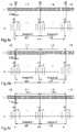
- FIGS. 4a to 4c schematically illustrate a comparison of the time axis t with a scanning pulse sequence (in the upper part in each case) and the path s with the respective number of path encoder signals in intervals I0 to I3 clarifies. It is shown in FIG. 4a that the starting point of the measuring interval I2 on the time axis t (t a2 ) coincides with the ending point of the measuring interval 1 (t e1 ).
- a a F + a O
- a is the acceleration signal
- a F is the portion in the direction of travel that is relevant for the verification of the displacement signal
- the correction factor K according to Eq. (1b) calculate without offset influences being included in the calculation. If the calculated value deviates significantly from 1, then - assuming that the accelerator is working properly - it must be assumed that there is a functional impairment (manipulation) on the displacement sensor or in the processing unit associated with it.
- the embodiment of the invention is not limited to the preferred exemplary embodiment specified above. Rather, a number of variants are conceivable which make use of the solution shown even in the case of fundamentally different types.
Landscapes
- Physics & Mathematics (AREA)
- General Physics & Mathematics (AREA)
- Engineering & Computer Science (AREA)
- Radar, Positioning & Navigation (AREA)
- Remote Sensing (AREA)
- Automation & Control Theory (AREA)
- Time Recorders, Dirve Recorders, Access Control (AREA)
- Testing Or Calibration Of Command Recording Devices (AREA)
Applications Claiming Priority (2)
| Application Number | Priority Date | Filing Date | Title |
|---|---|---|---|
| DE4435014A DE4435014A1 (de) | 1994-09-23 | 1994-09-23 | Vorrichtung zur Erfassung von Fortbewegungsvorgängen |
| DE4435014 | 1994-09-23 |
Publications (2)
| Publication Number | Publication Date |
|---|---|
| EP0703431A2 true EP0703431A2 (fr) | 1996-03-27 |
| EP0703431A3 EP0703431A3 (fr) | 1998-04-01 |
Family
ID=6529640
Family Applications (1)
| Application Number | Title | Priority Date | Filing Date |
|---|---|---|---|
| EP95250233A Withdrawn EP0703431A3 (fr) | 1994-09-23 | 1995-09-25 | Dispositif de saisi de processus de mouvement |
Country Status (2)
| Country | Link |
|---|---|
| EP (1) | EP0703431A3 (fr) |
| DE (1) | DE4435014A1 (fr) |
Cited By (3)
| Publication number | Priority date | Publication date | Assignee | Title |
|---|---|---|---|---|
| EP1669940A1 (fr) * | 1994-10-03 | 2006-06-14 | QUALCOMM Incorporated | Procédé et appareil de détection de dysfonctionnements dans un dispositif d'enregistrement de données pour véhicule |
| CN103217155A (zh) * | 2012-01-20 | 2013-07-24 | 株式会社森精机制作所 | 移位检测方法和移位检测单元 |
| CN109737953A (zh) * | 2019-01-04 | 2019-05-10 | 四川虹美智能科技有限公司 | 一种基于加速度传感器的位移检测方法和装置 |
Families Citing this family (9)
| Publication number | Priority date | Publication date | Assignee | Title |
|---|---|---|---|---|
| EP0871147A3 (fr) | 1997-04-09 | 2001-04-18 | Volkswagen Aktiengesellschaft | Procédé de stockage des données liées aux accidents de véhicule automobile et mémoire pour données d'accident |
| DE19732554A1 (de) * | 1997-07-29 | 1999-02-04 | Itt Mfg Enterprises Inc | Verfahren und Vorrichtung zur Bestimmung der Fahrzeuggeschwindigkeit |
| DE10024394C5 (de) * | 2000-05-17 | 2008-11-06 | Siemens Ag | Ermittlungsverfahren für eine Istgeschwindigkeit eines bewegbaren Verfahrelements |
| DE102006040297B4 (de) | 2006-08-29 | 2010-12-09 | Continental Automotive Gmbh | Geschwindigkeitserfassung für ein Tachographensystem |
| DE102012215601A1 (de) * | 2012-09-03 | 2014-03-06 | Continental Automotive Gmbh | Verfahren und Vorrichtung zum Ermitteln eines Werts einer bewegungsabhängigen Größe |
| DE102014212760A1 (de) * | 2014-07-02 | 2015-03-19 | Robert Bosch Gmbh | Verfahren und Vorrichtung zur Plausibilisierung von Geschwindigkeitsdaten |
| DE102014213943A1 (de) * | 2014-07-17 | 2016-01-21 | Robert Bosch Gmbh | Vorrichtung und Verfahren zur Erzeugung eines Geschwindigkeitswertes |
| DE102017212729A1 (de) | 2017-07-25 | 2019-01-31 | Continental Teves Ag & Co. Ohg | Verfahren zum Betreiben eines Datenschreibers für Fahrzeuge |
| DE102017212728A1 (de) | 2017-07-25 | 2019-01-31 | Continental Teves Ag & Co. Ohg | Datenschreiber für Fahrzeuge mit zumindest einer Batterie |
Citations (5)
| Publication number | Priority date | Publication date | Assignee | Title |
|---|---|---|---|---|
| EP0322532A1 (fr) | 1987-12-24 | 1989-07-05 | Bodenseewerk Gerätetechnik GmbH | Dispositif pour la détermination de la vitesse des véhicules |
| DE3839221A1 (de) | 1988-08-01 | 1990-02-08 | Morche Dirk W Dipl Ing | Fahrdatenspeicher |
| DE4022312A1 (de) | 1990-07-13 | 1992-01-23 | Manfred Laschuetza | Vorrichtung fuer kraftfahrzeuge zur erleichterung und ueberpruefung der einhaltung von strassenverkehrsvorschriften |
| EP0517062A1 (fr) | 1991-06-04 | 1992-12-09 | The Goodyear Tire & Rubber Company | Dispositif d'étiquetage pour pneus |
| EP0553478A2 (fr) | 1992-01-30 | 1993-08-04 | VDO Adolf Schindling AG | Installation pour justifier des perturbations de la transmission de signaux dans des véhicules |
Family Cites Families (14)
| Publication number | Priority date | Publication date | Assignee | Title |
|---|---|---|---|---|
| DE2813078C2 (de) * | 1978-03-25 | 1979-12-20 | Standard Elektrik Lorenz Ag, 7000 Stuttgart | Einrichtung zur Weg- und Geschwindigkeitsmessung bei spurgebundenen Fahrzeugen |
| DE2818202C2 (de) * | 1978-04-26 | 1987-03-26 | Bodenseewerk Gerätetechnik GmbH, 7770 Überlingen | Navigationsgerät für Land-, Luft- oder Seefahrzeuge |
| DE3248192A1 (de) * | 1982-08-25 | 1984-03-01 | Roland 7770 Überlingen Heubeck | Vorrichtung zur registrierung bzw. aufzeichnung von daten eines kraftfahrzeuges vor einem unfall |
| DE3405757A1 (de) * | 1983-02-26 | 1984-10-04 | Edmund 7016 Gerlingen Zottnik | Unfalldatenschreiber |
| DE3342553A1 (de) * | 1983-11-25 | 1985-06-05 | Volkswagenwerk Ag, 3180 Wolfsburg | Einrichtung zur ermittlung der zumindest annaehernd wahren fahrgeschwindigkeit des kraftfahrzeuges |
| DE3520383A1 (de) * | 1985-06-07 | 1986-12-11 | Jost, Hubertus, Dr., 6530 Bingen | Crashanzeiger |
| DE3839959A1 (de) * | 1988-10-06 | 1990-04-12 | Bosch Gmbh Robert | Notrufeinrichtung fuer ein fahrzeug |
| US5181181A (en) * | 1990-09-27 | 1993-01-19 | Triton Technologies, Inc. | Computer apparatus input device for three-dimensional information |
| JP3030866B2 (ja) * | 1990-12-26 | 2000-04-10 | 住友電気工業株式会社 | 重力式加速度計の零点補正装置 |
| CH681931A5 (fr) * | 1991-05-29 | 1993-06-15 | Ascom Zelcom Ag | |
| JP3058942B2 (ja) * | 1991-06-27 | 2000-07-04 | 三菱電機株式会社 | ナビゲーション装置 |
| DE4139339C2 (de) * | 1991-11-29 | 1995-10-05 | Loebl Jean Pierre Dipl Ing | Verfahren zum nachträglichen Nachweis der Reihenfolge, der Richtung und gegebenenfalls der Intensität mehrerer auf ein Fahrzeug einwirkenden Crash-Stöße |
| CH687352C9 (de) * | 1992-09-07 | 2001-07-13 | Diwag Ag | Verfahren und vorrichtung zum bestimmen von betriebs- und/oder fahrdaten eines fahrzeuges bzw. sich daraus ergebender geldbetraege. |
| DE4326831A1 (de) * | 1993-08-10 | 1995-02-16 | Georg Dipl Ing Voetterl | Fahrtschreiber für Kraftfahrzeuge |
-
1994
- 1994-09-23 DE DE4435014A patent/DE4435014A1/de not_active Withdrawn
-
1995
- 1995-09-25 EP EP95250233A patent/EP0703431A3/fr not_active Withdrawn
Patent Citations (5)
| Publication number | Priority date | Publication date | Assignee | Title |
|---|---|---|---|---|
| EP0322532A1 (fr) | 1987-12-24 | 1989-07-05 | Bodenseewerk Gerätetechnik GmbH | Dispositif pour la détermination de la vitesse des véhicules |
| DE3839221A1 (de) | 1988-08-01 | 1990-02-08 | Morche Dirk W Dipl Ing | Fahrdatenspeicher |
| DE4022312A1 (de) | 1990-07-13 | 1992-01-23 | Manfred Laschuetza | Vorrichtung fuer kraftfahrzeuge zur erleichterung und ueberpruefung der einhaltung von strassenverkehrsvorschriften |
| EP0517062A1 (fr) | 1991-06-04 | 1992-12-09 | The Goodyear Tire & Rubber Company | Dispositif d'étiquetage pour pneus |
| EP0553478A2 (fr) | 1992-01-30 | 1993-08-04 | VDO Adolf Schindling AG | Installation pour justifier des perturbations de la transmission de signaux dans des véhicules |
Cited By (4)
| Publication number | Priority date | Publication date | Assignee | Title |
|---|---|---|---|---|
| EP1669940A1 (fr) * | 1994-10-03 | 2006-06-14 | QUALCOMM Incorporated | Procédé et appareil de détection de dysfonctionnements dans un dispositif d'enregistrement de données pour véhicule |
| CN103217155A (zh) * | 2012-01-20 | 2013-07-24 | 株式会社森精机制作所 | 移位检测方法和移位检测单元 |
| CN103217155B (zh) * | 2012-01-20 | 2017-10-13 | 德马吉森精机株式会社 | 设备的移位检测及控制方法、设备的移位检测及控制单元 |
| CN109737953A (zh) * | 2019-01-04 | 2019-05-10 | 四川虹美智能科技有限公司 | 一种基于加速度传感器的位移检测方法和装置 |
Also Published As
| Publication number | Publication date |
|---|---|
| DE4435014A1 (de) | 1996-03-28 |
| EP0703431A3 (fr) | 1998-04-01 |
Similar Documents
| Publication | Publication Date | Title |
|---|---|---|
| EP1237760B1 (fr) | Procede et dispositif pour determiner l'angle de rotation absolu d'un objet tournant autour d'un axe de rotation approximativement horizontal | |
| EP2111557B1 (fr) | Procédé et dispositif pour déterminer la vitesse d'un véhicule | |
| DE102005047021B3 (de) | Anordnung zur Bestimmung eines absoluten Neigungswinkels gegenüber der Horizontalen | |
| EP0703431A2 (fr) | Dispositif de saisi de processus de mouvement | |
| EP0836566B1 (fr) | Saisie et evaluation de valeurs critiques en termes de securite | |
| EP2377102B1 (fr) | Agencement de capteur, agencement de tachygraphe et procédé de détection d'une manipulation | |
| WO1999008914A1 (fr) | Procede et dispositif permettant de determiner la vitesse de reference d'un vehicule | |
| DE69414042T2 (de) | Verfahren zur Eichung eines Einpunktaufprallsensors | |
| EP1284204A2 (fr) | Dispositif pour l'allocation des positions des pneumatiques d'un véhicule | |
| EP2544935B1 (fr) | Procédé et dispositif de détection d'un écart d'un signal de vitesse de rotation d'un capteur de vitesse de rotation | |
| EP2998710B1 (fr) | Procede et dispositif de transmission numerique cyclique d'une valeur de position d'un objet en mouvement a l'aide d'une masse inerte | |
| DE68909251T2 (de) | Verfahren und Vorrichtung zur Bestimmung der Lenkstellung eines Kraftfahrzeuglenkungssystems. | |
| DE4328442A1 (de) | Anordnung zur Ermittlung der Fahrgeschwindigkeit eines Fahrzeuges | |
| DE2818388C2 (fr) | ||
| EP0316888A1 (fr) | Dispositif de mesure de distance et de vitesse pour des véhicules guidés sur une voie | |
| DE3938039A1 (de) | Verfahren zur ermittlung der querbeschleunigung eines kraftfahrzeuges | |
| DE19725058A1 (de) | Vorrichtung mit redundanten Kanälen zwischen einer Sensoreinrichtung und einer Auswerteeinrichtung | |
| DE102022208535A1 (de) | Verfahren zum Ermitteln eines funktionalen Zusammenhangs einer Antriebseinheit sowie Fahrzeug | |
| EP3990322B1 (fr) | Procédé d'étalonnage de l'orientation d'un capteur d'accélération disposé dans un véhicule | |
| DE10260416A1 (de) | Verfahren und System zur Bestimmung der Geschwindigkeit eines Fahrzeugs | |
| DE4008167A1 (de) | Verfahren und vorrichtung zur ermittlung eines lenkeinschlagwinkels | |
| DE2547057C2 (de) | Vorrichtung zur Messung der Ausrichtung bzw. Ausfluchtung von Gleisen, insbesondere Eisenbahngleisen | |
| EP1014092A2 (fr) | Procédé et dispositif pour la détermination interne de la vitesse d'un véhicule terrestre | |
| DE102012200796A1 (de) | System und Verfahren zur plausibilisierten Beschleunigungsmessung | |
| WO2023021131A1 (fr) | Procédé de détermination d'une relation fonctionnelle entre un paramètre de fonctionnement d'une unité d'entraînement d'un véhicule et un champ magnétique parasite |
Legal Events
| Date | Code | Title | Description |
|---|---|---|---|
| PUAI | Public reference made under article 153(3) epc to a published international application that has entered the european phase |
Free format text: ORIGINAL CODE: 0009012 |
|
| AK | Designated contracting states |
Kind code of ref document: A2 Designated state(s): AT BE CH DE DK ES FR GB IT LI NL SE |
|
| RAP3 | Party data changed (applicant data changed or rights of an application transferred) |
Owner name: ETC TRANSPORT CONSULTANTS GMBH Owner name: MESSELEKTRONIK DRESDEN GMBH Owner name: EBERT, ROLF, PROF. DR. MED. Owner name: KOLLEY, KLAUS |
|
| RAP1 | Party data changed (applicant data changed or rights of an application transferred) |
Owner name: ETC TRANSPORT CONSULTANTS GMBH Owner name: EBERT, ROLF, PROF. DR. MED. Owner name: KOLLEY, KLAUS |
|
| PUAL | Search report despatched |
Free format text: ORIGINAL CODE: 0009013 |
|
| AK | Designated contracting states |
Kind code of ref document: A3 Designated state(s): AT BE CH DE DK ES FR GB IT LI NL SE |
|
| STAA | Information on the status of an ep patent application or granted ep patent |
Free format text: STATUS: THE APPLICATION IS DEEMED TO BE WITHDRAWN |
|
| 18D | Application deemed to be withdrawn |
Effective date: 19981004 |