EP0702128A1 - Mécanisme maneton-bielle pour la transformation d'un mouvement alternatif en un mouvement rotatif - Google Patents
Mécanisme maneton-bielle pour la transformation d'un mouvement alternatif en un mouvement rotatif Download PDFInfo
- Publication number
- EP0702128A1 EP0702128A1 EP95830374A EP95830374A EP0702128A1 EP 0702128 A1 EP0702128 A1 EP 0702128A1 EP 95830374 A EP95830374 A EP 95830374A EP 95830374 A EP95830374 A EP 95830374A EP 0702128 A1 EP0702128 A1 EP 0702128A1
- Authority
- EP
- European Patent Office
- Prior art keywords
- cam
- stroke
- wheel
- crank system
- profile
- Prior art date
- Legal status (The legal status is an assumption and is not a legal conclusion. Google has not performed a legal analysis and makes no representation as to the accuracy of the status listed.)
- Granted
Links
Images


Classifications
-
- F—MECHANICAL ENGINEERING; LIGHTING; HEATING; WEAPONS; BLASTING
- F02—COMBUSTION ENGINES; HOT-GAS OR COMBUSTION-PRODUCT ENGINE PLANTS
- F02B—INTERNAL-COMBUSTION PISTON ENGINES; COMBUSTION ENGINES IN GENERAL
- F02B41/00—Engines characterised by special means for improving conversion of heat or pressure energy into mechanical power
-
- F—MECHANICAL ENGINEERING; LIGHTING; HEATING; WEAPONS; BLASTING
- F01—MACHINES OR ENGINES IN GENERAL; ENGINE PLANTS IN GENERAL; STEAM ENGINES
- F01B—MACHINES OR ENGINES, IN GENERAL OR OF POSITIVE-DISPLACEMENT TYPE, e.g. STEAM ENGINES
- F01B9/00—Reciprocating-piston machines or engines characterised by connections between pistons and main shafts and not specific to preceding groups
- F01B9/04—Reciprocating-piston machines or engines characterised by connections between pistons and main shafts and not specific to preceding groups with rotary main shaft other than crankshaft
- F01B9/06—Reciprocating-piston machines or engines characterised by connections between pistons and main shafts and not specific to preceding groups with rotary main shaft other than crankshaft the piston motion being transmitted by curved surfaces
-
- F—MECHANICAL ENGINEERING; LIGHTING; HEATING; WEAPONS; BLASTING
- F02—COMBUSTION ENGINES; HOT-GAS OR COMBUSTION-PRODUCT ENGINE PLANTS
- F02B—INTERNAL-COMBUSTION PISTON ENGINES; COMBUSTION ENGINES IN GENERAL
- F02B75/00—Other engines
- F02B75/16—Engines characterised by number of cylinders, e.g. single-cylinder engines
- F02B75/18—Multi-cylinder engines
- F02B75/22—Multi-cylinder engines with cylinders in V, fan, or star arrangement
-
- F—MECHANICAL ENGINEERING; LIGHTING; HEATING; WEAPONS; BLASTING
- F01—MACHINES OR ENGINES IN GENERAL; ENGINE PLANTS IN GENERAL; STEAM ENGINES
- F01B—MACHINES OR ENGINES, IN GENERAL OR OF POSITIVE-DISPLACEMENT TYPE, e.g. STEAM ENGINES
- F01B9/00—Reciprocating-piston machines or engines characterised by connections between pistons and main shafts and not specific to preceding groups
- F01B9/04—Reciprocating-piston machines or engines characterised by connections between pistons and main shafts and not specific to preceding groups with rotary main shaft other than crankshaft
- F01B9/06—Reciprocating-piston machines or engines characterised by connections between pistons and main shafts and not specific to preceding groups with rotary main shaft other than crankshaft the piston motion being transmitted by curved surfaces
- F01B2009/061—Reciprocating-piston machines or engines characterised by connections between pistons and main shafts and not specific to preceding groups with rotary main shaft other than crankshaft the piston motion being transmitted by curved surfaces by cams
- F01B2009/063—Mono-lobe cams
Definitions
- the present invention relates to a crank mechanism system for the transformation of reciprocating motion into rotary motion, particularly suitable for reciprocating endothermic engines.
- the invention refers to a system of the above kind that allows to improve the operation of a thermodynamic cycle and the exploitation of the forces obtained by the same thermodynamic cycle.
- Force Fb is obtained by the vectorial composition of force Fn, produced by the thermodynamic cycle, and of the force F, due to the reaction of the wall of the cylinder to the piston thrust, said thrust being due to the inclination ⁇ of the connecting rod axis. Said thrust determines a friction loss.
- Mm is the torque
- F is the force acting on the piston head produced by the thermodynamic cycle
- r is the crank radius
- ⁇ is the crank angle with respect to the cylinder axis
- ⁇ is the r/l ratio.
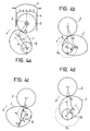
- thermodynamic cycle which is approximately represented for a four-stroke endothermic engine with an Otto cycle (having the ignition of the air - combustible by a controlled spark) in figure by a Cartesian diagram wherein the abscissa indicates the displacement of the piston and the ordinate the pressure within the cylinder above the piston head.
- the real cycle shown by a full line, covers a lower area than the theoretical cycle (shown by a hatched line) for several reasons, among which one of the most important is the one deriving from the fact that the combustion controlled by the spark does not instantaneously occur at the TDC, but during a certain period of time, so that the piston during its reciprocating motion makes a part of the stroke toward the TDC and a part of positive stroke after the TDC, before that completely occurs the fuel combustion.
- the Applicant has realized a crank mechanism that allows to obtain remarkable advantages with respect to the presently available solutions, further realizing a solution advantageously adaptable by the manufacturers.
- the solution according to the invention allows to realize a working cycle with a constant volume combustion.
- the solution proposed allows to realize cycles with a variable amplitude, without employing the misalignment, within important limits.
- Adopting the solution proposed according to the present invention it can be manufactured an engine having reduced dimensions, and thus lighter and cheaper.
- the invention allows to produce employing the production lines, machines and technologies already existing.
- Another advantage obtained by the system according to the invention is the one relevant to the solution of the stratified charge problem, in order to reach the zero value pollution provided by the laws for the end of the nineties.
- crank mechanism replacing the traditional connecting rod - crank assembly by the combination of a wheel, or rotary connecting rod, idly mounted on the piston pin, and of a cam mounted on the output shaft.
- crank system for the transformation of reciprocating linear motion into rotary motion, particularly suitable for reciprocating endothermic engines, comprising a wheel or rotating connection rod, idly provided on the engine piston pin, and a cam, provided on the output shaft, having a perimetral profile made up of at least two segments or cam arches for the optimisation of the engine cycle strokes, said wheel rotating along the profile of said cam with a coupling characterized by the absence of friction or by a minimum friction.
- said cam could have a first profile segment having one or more curvatures so as to optimise the induction stroke and the expansion stroke, and a second profile segment having one or more curvatures so as to optimize the compression and exhaust strokes.
- said cam can provide further segments or arches to optimize the combustion, particularly to obtain a constant volume combustion, in correspondence of the TDC, and the optimisation of the expansion stroke, in correspondence of the BDC.
- said further segments or arches will have a constant curvature ray corresponding to the distance between the engine axis and the curvature determining the Bottom Dead Centre, and respectively the Top Dead Centre. It must in fact taken into consideration that if the wheel connected to the piston rolls along a profile concentric with respect to rotation axis of the output shaft, the piston remains stopped in its rectilinear motion along the cylinder while the output shaft continues its rotation.
- the piston is stopped at the BDC, making it occurring first the complete expansion of the combustion products using all the expansion stroke before opening the exhaust valve.
- the complete stroke can occur along an angle after the TDC chosen in the most convenient way by the designer, suitably shaping the cam profile.
- the four strokes lasts 720° of rotation of the output shaft, i.e. 2 complete revolutions.
- the four - stroke engine realized according to the invention operates in 2 complete revolutions, i.e. 720° but, in the preferred embodiment, in 5 or 6 strokes:
- strokes V and VI could be also unified.
- said wheel and said cam are realized with such a material to make that the compression stress exerted by the wheel remains within the elasticity limits of the materials.
- said means for maintaining the contact are comprised of a little connecting rod, freely swinging on the same axis of the wheel and provided at the bottom with a projection coupling with a profile concentric with respect to the outer profile of the cam, and accurately reproducing the same.
- said means can be comprised of a rod, constrained at one end, with one or more degrees of freedom, to the piston and to the other end constrained to an elastic system absorbing the inertial energy during the stroke from the Bottom Dead Centre to the Top Dead Centre, giving back the same energy during the first part of the stroke from the Top Dead Centre to the Bottom Dead Centre.
- Said elastic system can be replaced, according to the invention, with an hydraulic system, eventually controlled by microprocessors.
- crank system according to the invention can be used in multi - cylinder engines, providing only one cam for all the cylinders, or one cam for each cylinder.
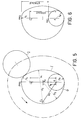
- system according to the invention comprises an assembly of parts replacing the system known as connecting rod - crank assembly and shown in figure 1.
- cam 1 integral with the output shaft, a wheel 2, freely rotating, thus idle, on the piston pin 3, and one element limiting the freedom of the piston 4 to move along the axis of the cylinder 5, and that will be more specifically described in the following.
- the numeric reference 6 indicates the output shaft.
- the motion of the wheel 2 along the cam 1, the profile of which will be suitably studied to optimize the stroke, is of the pure rolling kind, i.e. without sliding, and therefore without friction, being it necessary to take care that the compression stress exerted by the wheel 2 is well within the elasticity limits of the material chosen for the wheel 2 and for the cam 1.
- Distances b1, b2, b3,, ecc. can be suitably chosen and can be a multiple of r, although the engine displacement remains equal to a: piston area x 2r.
- ⁇ r/l(according to the prior art ⁇ is equal to about 0.25).
- r b1, b2, b3, ecc, the value of which is obtained adding the wheel 2 ray (that in this example is constant since the wheel 2 has been assumed as a circle) and the curvature ray of the several profile length of the cam 1.
- the solution according to the invention can be advantageously used for multi - cylinder engines, providing a sole cam 1 for all the cylinders,- or a number of cams 1 corresponding to the number of cylinders.
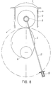
- the device of figure 7 comprises a little connecting rod 7, provided coaxially behind the wheel 2 and having at the bottom a projection 8 coupling with the rear profile 9 of the cam 1, said rear profile 9 exactly reproducing the outer profile of the cam 1.
- a wheel or slide 10 is provided, in order to make the sliding of the little connecting rod 7 along the profile 9 completely not influential for the motion of the cam 1.
- the little connecting rod has only the aim of maintaining constant the distance between the centre of the wheel 2 and the outer profile of the cam 1.
- the device comprises a rod 11, constrained, with one or more degrees of freedom, to the piston 4, for example at the lower part of the same piston 4 (in the figure the rod 11 is constrained to the pin 3 of the piston 4).
- the other end of the rod 11 is constrained to an elastic element 12, suitable to absorb the inertial energy of the piston 4 during its stroke from the BDC to the TDC, giving it back during the first part of the stroke from the TDC to the BDC.
- the elastic element can be replaced with an hydraulic system, eventually controlled by microprocessor.
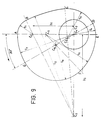
- figure 9 it is shown an example of multicenter cam profile allowing to maintain a constant volume during the combustion.
- C1, C2, C3, C4, C5, C6, C7 define the multicenter profile, r1, ...2016 , r7 the curvature rays and A, B, C, D, E, F, G, the tangency points.
- the diameter of the rotating connecting rod 2 is equal to 70 mm.
- the arch A-B-C-D is the arch for expansion and induction strokes, along the arch D-E the piston is stopped in correspondence of the BDC, the arch E-F-G is the arch for the exhaust and compression strokes, while along the arch G-A the piston is stopped in correspondence of the TDC.
Applications Claiming Priority (2)
| Application Number | Priority Date | Filing Date | Title |
|---|---|---|---|
| ITRM940580 | 1994-09-13 | ||
| ITRM940580A IT1272806B (it) | 1994-09-13 | 1994-09-13 | "sistema di manovellismo per la trasformazione del moto rettilineo alternato in moto rotatorio, in particolare adatto per motori endotermici alternativi". |
Publications (2)
| Publication Number | Publication Date |
|---|---|
| EP0702128A1 true EP0702128A1 (fr) | 1996-03-20 |
| EP0702128B1 EP0702128B1 (fr) | 1999-05-26 |
Family
ID=11402722
Family Applications (1)
| Application Number | Title | Priority Date | Filing Date |
|---|---|---|---|
| EP95830374A Expired - Lifetime EP0702128B1 (fr) | 1994-09-13 | 1995-09-08 | Mécanisme maneton-bielle pour la transformation d'un mouvement alternatif en un mouvement rotatif |
Country Status (16)
| Country | Link |
|---|---|
| US (1) | US5647308A (fr) |
| EP (1) | EP0702128B1 (fr) |
| JP (1) | JP3616168B2 (fr) |
| KR (1) | KR960011068A (fr) |
| CN (1) | CN1053491C (fr) |
| AT (1) | ATE180542T1 (fr) |
| AU (1) | AU692578B2 (fr) |
| CA (1) | CA2157991C (fr) |
| DE (1) | DE69509845T2 (fr) |
| ES (1) | ES2136268T3 (fr) |
| HU (1) | HU222393B1 (fr) |
| IT (1) | IT1272806B (fr) |
| PL (1) | PL177464B1 (fr) |
| RO (1) | RO115661B1 (fr) |
| RU (1) | RU2125170C1 (fr) |
| TW (1) | TW309578B (fr) |
Cited By (4)
| Publication number | Priority date | Publication date | Assignee | Title |
|---|---|---|---|---|
| WO1998013581A1 (fr) * | 1996-09-27 | 1998-04-02 | George Frederic Galvin | Moteur |
| EP1134381A1 (fr) | 2000-03-15 | 2001-09-19 | Gerhard Lehofer | Machine à pistons |
| DE10138837A1 (de) * | 2001-08-14 | 2003-02-27 | Helmut Obieglo | Hubkolbenaggregat |
| WO2016126366A3 (fr) * | 2015-02-04 | 2016-10-13 | Google Inc. | Came à joint à phase |
Families Citing this family (16)
| Publication number | Priority date | Publication date | Assignee | Title |
|---|---|---|---|---|
| US6698394B2 (en) | 1999-03-23 | 2004-03-02 | Thomas Engine Company | Homogenous charge compression ignition and barrel engines |
| US6662775B2 (en) | 1999-03-23 | 2003-12-16 | Thomas Engine Company, Llc | Integral air compressor for boost air in barrel engine |
| US8046299B2 (en) | 2003-10-15 | 2011-10-25 | American Express Travel Related Services Company, Inc. | Systems, methods, and devices for selling transaction accounts |
| EP1709296B1 (fr) * | 2004-01-12 | 2018-10-10 | LiquidPiston, Inc. | Moteur a combustion a cycle hybride et procedes associes |
| WO2008016979A2 (fr) | 2006-08-02 | 2008-02-07 | Liquidpiston, Inc. | Moteur rotatif à cycle hybride |
| CA2732810A1 (fr) * | 2008-08-04 | 2010-02-11 | Liquidpiston, Inc. | Moteurs et procedes d'addition de chaleur isochore |
| US8281764B2 (en) * | 2009-06-25 | 2012-10-09 | Onur Gurler | Half cycle eccentric crank-shafted engine |
| CN102042376A (zh) * | 2010-02-07 | 2011-05-04 | 福建南安三井机械厂有限公司 | 凸轮双滚轮机构 |
| CN102606675A (zh) * | 2011-01-25 | 2012-07-25 | 朱譞晟 | 内燃机的平衡装置 |
| ES2590777T3 (es) | 2011-03-29 | 2016-11-23 | Liquidpiston, Inc. | Motor de rotor cicloide |
| EP2882936B1 (fr) * | 2012-08-10 | 2018-05-16 | Barnes Group Inc. | Tige de liaison souple |
| EP2948630B1 (fr) | 2013-01-25 | 2019-08-21 | LiquidPiston, Inc. | Moteur rotatif refroidi par air |
| ES2757403T3 (es) * | 2016-12-08 | 2020-04-29 | Knauer Wss Geraete Gmbh | Mecanismo de levas para la implementación de una carrera variable |
| CN108019327B (zh) * | 2017-12-15 | 2019-05-03 | 安徽理工大学 | 一种凹槽凸轮恒流量钻井往复泵 |
| RU2730195C1 (ru) * | 2019-11-18 | 2020-08-19 | Андрей Викторович Юндин | Двигатель внутреннего сгорания (цикл юндина) |
| RU207599U1 (ru) * | 2020-12-04 | 2021-11-03 | Федеральное государственное бюджетное образовательное учреждение высшего образования "Чувашский государственный университет имени И.Н. Ульянова" | Преобразователь энергии газа |
Citations (5)
| Publication number | Priority date | Publication date | Assignee | Title |
|---|---|---|---|---|
| US1784902A (en) * | 1929-10-22 | 1930-12-16 | Joseph V Maurais | Power-shaft connection for internal-combustion engines |
| US2006498A (en) * | 1934-01-15 | 1935-07-02 | Dasset Emile | Internal combustion engine |
| US2249951A (en) * | 1939-12-04 | 1941-07-22 | M S Kingston | Energy transmission means |
| US4966067A (en) * | 1989-02-27 | 1990-10-30 | Sundstrand Corporation | Involute cam actuator with piston drive |
| FR2655378A1 (fr) * | 1989-12-06 | 1991-06-07 | Boulanger Claude | Systeme de moteur a 2 temps ayant 4 cycles. |
Family Cites Families (15)
| Publication number | Priority date | Publication date | Assignee | Title |
|---|---|---|---|---|
| US1806608A (en) * | 1931-05-26 | John bryant | ||
| US629039A (en) * | 1898-05-16 | 1899-07-18 | Samuel W Luitwieler | Mechanism for producing reciprocating motion. |
| US1873015A (en) * | 1929-06-05 | 1932-08-23 | Frank J Omo | Internal combustion engine |
| US2120657A (en) * | 1937-01-06 | 1938-06-14 | Henry R Tucker | Internal combustion engine |
| US2417649A (en) * | 1943-12-10 | 1947-03-18 | Johansen Carl Steffen | Two-stroke internal-combustion engine |
| US3572209A (en) * | 1967-11-28 | 1971-03-23 | Hal F Aldridge | Radial engine |
| DE1776054A1 (de) * | 1968-09-12 | 1970-11-12 | Hatz Motoren | Kolbenmaschine |
| US3998200A (en) * | 1974-10-16 | 1976-12-21 | Sudholt Kenneth J | Reciprocating engine |
| US4149498A (en) * | 1976-11-19 | 1979-04-17 | Ferrell Arthur T | Internal combustion engine |
| DE2908196A1 (de) * | 1979-03-02 | 1980-09-11 | Heinrich Schiller | Verbrennungs-viertakthubkolbenmotor ohne kurbelwelle der bei einer umdrehung den ganzen arbeitszyklus abschliesst |
| US4301776A (en) * | 1979-06-04 | 1981-11-24 | Fleming Joseph W | Crankshaft apparatus |
| US4493296A (en) * | 1981-05-28 | 1985-01-15 | Williams Gerald J | Three cycle engine with varying combustion chamber volume |
| US4489681A (en) * | 1981-12-02 | 1984-12-25 | Jackson Francis W | Multiple piston expansion chamber engine |
| US4430967A (en) * | 1982-02-08 | 1984-02-14 | Williams Robert H | Two cycle diesel engine |
| GB2278773B (en) * | 1993-06-11 | 1997-04-09 | Clares Equip Ltd | Steerable mobile load carrier and swivel castor therefor |
-
1994
- 1994-09-13 IT ITRM940580A patent/IT1272806B/it active IP Right Grant
-
1995
- 1995-09-07 US US08/528,646 patent/US5647308A/en not_active Expired - Fee Related
- 1995-09-07 TW TW084109427A patent/TW309578B/zh active
- 1995-09-08 AT AT95830374T patent/ATE180542T1/de not_active IP Right Cessation
- 1995-09-08 EP EP95830374A patent/EP0702128B1/fr not_active Expired - Lifetime
- 1995-09-08 ES ES95830374T patent/ES2136268T3/es not_active Expired - Lifetime
- 1995-09-08 DE DE69509845T patent/DE69509845T2/de not_active Expired - Fee Related
- 1995-09-11 CA CA002157991A patent/CA2157991C/fr not_active Expired - Fee Related
- 1995-09-12 RU RU95115545A patent/RU2125170C1/ru not_active IP Right Cessation
- 1995-09-12 RO RO95-01595A patent/RO115661B1/ro unknown
- 1995-09-12 AU AU30643/95A patent/AU692578B2/en not_active Ceased
- 1995-09-13 PL PL95310427A patent/PL177464B1/pl not_active IP Right Cessation
- 1995-09-13 KR KR1019950029735A patent/KR960011068A/ko not_active Application Discontinuation
- 1995-09-13 HU HU9502675A patent/HU222393B1/hu not_active IP Right Cessation
- 1995-09-13 CN CN95115735A patent/CN1053491C/zh not_active Expired - Fee Related
- 1995-09-13 JP JP23548895A patent/JP3616168B2/ja not_active Expired - Fee Related
Patent Citations (5)
| Publication number | Priority date | Publication date | Assignee | Title |
|---|---|---|---|---|
| US1784902A (en) * | 1929-10-22 | 1930-12-16 | Joseph V Maurais | Power-shaft connection for internal-combustion engines |
| US2006498A (en) * | 1934-01-15 | 1935-07-02 | Dasset Emile | Internal combustion engine |
| US2249951A (en) * | 1939-12-04 | 1941-07-22 | M S Kingston | Energy transmission means |
| US4966067A (en) * | 1989-02-27 | 1990-10-30 | Sundstrand Corporation | Involute cam actuator with piston drive |
| FR2655378A1 (fr) * | 1989-12-06 | 1991-06-07 | Boulanger Claude | Systeme de moteur a 2 temps ayant 4 cycles. |
Cited By (7)
| Publication number | Priority date | Publication date | Assignee | Title |
|---|---|---|---|---|
| WO1998013581A1 (fr) * | 1996-09-27 | 1998-04-02 | George Frederic Galvin | Moteur |
| EP1134381A1 (fr) | 2000-03-15 | 2001-09-19 | Gerhard Lehofer | Machine à pistons |
| WO2001069063A1 (fr) | 2000-03-15 | 2001-09-20 | Gerhard Lehofer | Moteur a pistons |
| US6926248B2 (en) | 2000-03-15 | 2005-08-09 | Gerhard Lehofer | Piston engine |
| DE10138837A1 (de) * | 2001-08-14 | 2003-02-27 | Helmut Obieglo | Hubkolbenaggregat |
| WO2016126366A3 (fr) * | 2015-02-04 | 2016-10-13 | Google Inc. | Came à joint à phase |
| US9651133B2 (en) | 2015-02-04 | 2017-05-16 | Google Inc. | Phased joint cam |
Also Published As
| Publication number | Publication date |
|---|---|
| ES2136268T3 (es) | 1999-11-16 |
| CN1129297A (zh) | 1996-08-21 |
| CA2157991A1 (fr) | 1996-03-14 |
| TW309578B (fr) | 1997-07-01 |
| HU222393B1 (hu) | 2003-06-28 |
| CN1053491C (zh) | 2000-06-14 |
| HUT74302A (en) | 1996-11-28 |
| RU2125170C1 (ru) | 1999-01-20 |
| PL177464B1 (pl) | 1999-11-30 |
| AU692578B2 (en) | 1998-06-11 |
| PL310427A1 (en) | 1996-03-18 |
| RO115661B1 (ro) | 2000-04-28 |
| HU9502675D0 (en) | 1995-11-28 |
| JPH08100668A (ja) | 1996-04-16 |
| ITRM940580A1 (it) | 1996-03-13 |
| EP0702128B1 (fr) | 1999-05-26 |
| ITRM940580A0 (it) | 1994-09-13 |
| AU3064395A (en) | 1996-03-28 |
| DE69509845D1 (de) | 1999-07-01 |
| DE69509845T2 (de) | 1999-12-30 |
| KR960011068A (ko) | 1996-04-20 |
| CA2157991C (fr) | 2004-02-10 |
| IT1272806B (it) | 1997-06-30 |
| JP3616168B2 (ja) | 2005-02-02 |
| ATE180542T1 (de) | 1999-06-15 |
| US5647308A (en) | 1997-07-15 |
Similar Documents
| Publication | Publication Date | Title |
|---|---|---|
| US5647308A (en) | Crank mechanism system for the transformation of reciprocating linear motion into rotary motion, particularly suitable for reciprocating endothermic engines | |
| US5927236A (en) | Variable stroke mechanism for internal combustion engine | |
| US3961607A (en) | Internal combustion engine | |
| US5546897A (en) | Internal combustion engine with stroke specialized cylinders | |
| US6230671B1 (en) | Variable compression and asymmetrical stroke internal combustion engine | |
| US4608951A (en) | Reciprocating piston engine | |
| US6976467B2 (en) | Reciprocating internal combustion engine | |
| US4011842A (en) | Piston machine | |
| US20010017122A1 (en) | Internal-combustion engine with improved reciprocating action | |
| US5060603A (en) | Internal combustion engine crankdisc and method of making same | |
| US4848282A (en) | Combustion engine having no connecting rods or crankshaft, of the radial cylinder type | |
| US4010611A (en) | Compression-expansion power device | |
| US3312206A (en) | Reciprocating engines | |
| US20020083908A1 (en) | Internal combustion engine with variable ratio crankshaft assembly | |
| US20120291755A1 (en) | Variable stroke mechanism for internal combustion engine | |
| RU95115545A (ru) | Кривошипная система для преобразования возвратно-поступательного линейного движения во вращательное движение, пригодная в частности для возвратно-поступательных эндотермических двигателей | |
| US3604402A (en) | Piston mechanism | |
| US5537957A (en) | Internal combustion engine | |
| WO1996035865A9 (fr) | Moteur a combustion interne | |
| SU1733652A1 (ru) | Двигатель внутреннего сгорани | |
| EP0016046A1 (fr) | Procede et dispositif d'augmentation du rendement d'un moteur a combustion interne et de reduction de son taux de pollution. | |
| US4967703A (en) | Machine having rotary reciprocating piston | |
| EP0027820A1 (fr) | Moteur a combustion interne a cylindres paralleles | |
| US5682852A (en) | Internal combustion engine | |
| JPS5996436A (ja) | 転がり球と案内溝によりピストンを往復動させる四サイクル機関 |
Legal Events
| Date | Code | Title | Description |
|---|---|---|---|
| PUAI | Public reference made under article 153(3) epc to a published international application that has entered the european phase |
Free format text: ORIGINAL CODE: 0009012 |
|
| AK | Designated contracting states |
Kind code of ref document: A1 Designated state(s): AT BE CH DE DK ES FR GB GR IE IT LI LU MC NL PT SE |
|
| 17P | Request for examination filed |
Effective date: 19960603 |
|
| 17Q | First examination report despatched |
Effective date: 19970603 |
|
| GRAG | Despatch of communication of intention to grant |
Free format text: ORIGINAL CODE: EPIDOS AGRA |
|
| GRAG | Despatch of communication of intention to grant |
Free format text: ORIGINAL CODE: EPIDOS AGRA |
|
| GRAH | Despatch of communication of intention to grant a patent |
Free format text: ORIGINAL CODE: EPIDOS IGRA |
|
| GRAH | Despatch of communication of intention to grant a patent |
Free format text: ORIGINAL CODE: EPIDOS IGRA |
|
| GRAA | (expected) grant |
Free format text: ORIGINAL CODE: 0009210 |
|
| AK | Designated contracting states |
Kind code of ref document: B1 Designated state(s): AT BE CH DE DK ES FR GB GR IE IT LI LU MC NL PT SE |
|
| PG25 | Lapsed in a contracting state [announced via postgrant information from national office to epo] |
Ref country code: GR Free format text: LAPSE BECAUSE OF NON-PAYMENT OF DUE FEES Effective date: 19990526 |
|
| REF | Corresponds to: |
Ref document number: 180542 Country of ref document: AT Date of ref document: 19990615 Kind code of ref document: T |
|
| REG | Reference to a national code |
Ref country code: CH Ref legal event code: EP |
|
| REF | Corresponds to: |
Ref document number: 69509845 Country of ref document: DE Date of ref document: 19990701 |
|
| RAP2 | Party data changed (patent owner data changed or rights of a patent transferred) |
Owner name: M.U.I. MOTOR UNION ITALIA S.R.L. |
|
| REG | Reference to a national code |
Ref country code: IE Ref legal event code: FG4D |
|
| REG | Reference to a national code |
Ref country code: CH Ref legal event code: NV Representative=s name: E. BLUM & CO. PATENTANWAELTE |
|
| PG25 | Lapsed in a contracting state [announced via postgrant information from national office to epo] |
Ref country code: PT Free format text: LAPSE BECAUSE OF FAILURE TO SUBMIT A TRANSLATION OF THE DESCRIPTION OR TO PAY THE FEE WITHIN THE PRESCRIBED TIME-LIMIT Effective date: 19990826 Ref country code: DK Free format text: LAPSE BECAUSE OF FAILURE TO SUBMIT A TRANSLATION OF THE DESCRIPTION OR TO PAY THE FEE WITHIN THE PRESCRIBED TIME-LIMIT Effective date: 19990826 |
|
| NLT2 | Nl: modifications (of names), taken from the european patent patent bulletin |
Owner name: M.U.I. MOTOR UNION ITALIA S.R.L. |
|
| PG25 | Lapsed in a contracting state [announced via postgrant information from national office to epo] |
Ref country code: LU Free format text: LAPSE BECAUSE OF NON-PAYMENT OF DUE FEES Effective date: 19990908 Ref country code: IE Free format text: LAPSE BECAUSE OF NON-PAYMENT OF DUE FEES Effective date: 19990908 |
|
| ET | Fr: translation filed | ||
| REG | Reference to a national code |
Ref country code: ES Ref legal event code: FG2A Ref document number: 2136268 Country of ref document: ES Kind code of ref document: T3 |
|
| PG25 | Lapsed in a contracting state [announced via postgrant information from national office to epo] |
Ref country code: MC Free format text: LAPSE BECAUSE OF NON-PAYMENT OF DUE FEES Effective date: 20000331 |
|
| PLBE | No opposition filed within time limit |
Free format text: ORIGINAL CODE: 0009261 |
|
| STAA | Information on the status of an ep patent application or granted ep patent |
Free format text: STATUS: NO OPPOSITION FILED WITHIN TIME LIMIT |
|
| 26N | No opposition filed | ||
| REG | Reference to a national code |
Ref country code: IE Ref legal event code: MM4A |
|
| REG | Reference to a national code |
Ref country code: GB Ref legal event code: IF02 |
|
| PGFP | Annual fee paid to national office [announced via postgrant information from national office to epo] |
Ref country code: CH Payment date: 20040818 Year of fee payment: 10 |
|
| PGFP | Annual fee paid to national office [announced via postgrant information from national office to epo] |
Ref country code: DE Payment date: 20040830 Year of fee payment: 10 |
|
| PGFP | Annual fee paid to national office [announced via postgrant information from national office to epo] |
Ref country code: GB Payment date: 20040908 Year of fee payment: 10 Ref country code: FR Payment date: 20040908 Year of fee payment: 10 |
|
| PGFP | Annual fee paid to national office [announced via postgrant information from national office to epo] |
Ref country code: AT Payment date: 20040909 Year of fee payment: 10 |
|
| PGFP | Annual fee paid to national office [announced via postgrant information from national office to epo] |
Ref country code: BE Payment date: 20040915 Year of fee payment: 10 |
|
| PGFP | Annual fee paid to national office [announced via postgrant information from national office to epo] |
Ref country code: ES Payment date: 20040916 Year of fee payment: 10 |
|
| PGFP | Annual fee paid to national office [announced via postgrant information from national office to epo] |
Ref country code: SE Payment date: 20040917 Year of fee payment: 10 |
|
| PGFP | Annual fee paid to national office [announced via postgrant information from national office to epo] |
Ref country code: NL Payment date: 20040929 Year of fee payment: 10 |
|
| PG25 | Lapsed in a contracting state [announced via postgrant information from national office to epo] |
Ref country code: IT Free format text: LAPSE BECAUSE OF NON-PAYMENT OF DUE FEES;WARNING: LAPSES OF ITALIAN PATENTS WITH EFFECTIVE DATE BEFORE 2007 MAY HAVE OCCURRED AT ANY TIME BEFORE 2007. THE CORRECT EFFECTIVE DATE MAY BE DIFFERENT FROM THE ONE RECORDED. Effective date: 20050908 Ref country code: GB Free format text: LAPSE BECAUSE OF NON-PAYMENT OF DUE FEES Effective date: 20050908 Ref country code: AT Free format text: LAPSE BECAUSE OF NON-PAYMENT OF DUE FEES Effective date: 20050908 |
|
| PG25 | Lapsed in a contracting state [announced via postgrant information from national office to epo] |
Ref country code: SE Free format text: LAPSE BECAUSE OF NON-PAYMENT OF DUE FEES Effective date: 20050909 |
|
| PG25 | Lapsed in a contracting state [announced via postgrant information from national office to epo] |
Ref country code: ES Free format text: LAPSE BECAUSE OF NON-PAYMENT OF DUE FEES Effective date: 20050910 |
|
| PG25 | Lapsed in a contracting state [announced via postgrant information from national office to epo] |
Ref country code: LI Free format text: LAPSE BECAUSE OF NON-PAYMENT OF DUE FEES Effective date: 20050930 Ref country code: CH Free format text: LAPSE BECAUSE OF NON-PAYMENT OF DUE FEES Effective date: 20050930 Ref country code: BE Free format text: LAPSE BECAUSE OF NON-PAYMENT OF DUE FEES Effective date: 20050930 |
|
| PG25 | Lapsed in a contracting state [announced via postgrant information from national office to epo] |
Ref country code: NL Free format text: LAPSE BECAUSE OF NON-PAYMENT OF DUE FEES Effective date: 20060401 Ref country code: DE Free format text: LAPSE BECAUSE OF NON-PAYMENT OF DUE FEES Effective date: 20060401 |
|
| REG | Reference to a national code |
Ref country code: CH Ref legal event code: PL |
|
| EUG | Se: european patent has lapsed | ||
| GBPC | Gb: european patent ceased through non-payment of renewal fee |
Effective date: 20050908 |
|
| PG25 | Lapsed in a contracting state [announced via postgrant information from national office to epo] |
Ref country code: FR Free format text: LAPSE BECAUSE OF NON-PAYMENT OF DUE FEES Effective date: 20060531 |
|
| NLV4 | Nl: lapsed or anulled due to non-payment of the annual fee |
Effective date: 20060401 |
|
| REG | Reference to a national code |
Ref country code: FR Ref legal event code: ST Effective date: 20060531 |
|
| REG | Reference to a national code |
Ref country code: ES Ref legal event code: FD2A Effective date: 20050910 |
|
| BERE | Be: lapsed |
Owner name: MOTOR UNION ITALIA S.R.L. *M.U.I. Effective date: 20050930 |