EP0701950A2 - A manually operated trigger type dispenser - Google Patents
A manually operated trigger type dispenser Download PDFInfo
- Publication number
- EP0701950A2 EP0701950A2 EP95306527A EP95306527A EP0701950A2 EP 0701950 A2 EP0701950 A2 EP 0701950A2 EP 95306527 A EP95306527 A EP 95306527A EP 95306527 A EP95306527 A EP 95306527A EP 0701950 A2 EP0701950 A2 EP 0701950A2
- Authority
- EP
- European Patent Office
- Prior art keywords
- cylinder
- valve
- plunger
- orifice
- flowing
- Prior art date
- Legal status (The legal status is an assumption and is not a legal conclusion. Google has not performed a legal analysis and makes no representation as to the accuracy of the status listed.)
- Withdrawn
Links
- 239000007788 liquid Substances 0.000 claims abstract description 100
- 238000004891 communication Methods 0.000 claims abstract description 4
- 239000007921 spray Substances 0.000 description 9
- 239000000463 material Substances 0.000 description 3
- 229920003023 plastic Polymers 0.000 description 3
- 239000004033 plastic Substances 0.000 description 3
- 238000012856 packing Methods 0.000 description 2
- CBENFWSGALASAD-UHFFFAOYSA-N Ozone Chemical compound [O-][O+]=O CBENFWSGALASAD-UHFFFAOYSA-N 0.000 description 1
- 238000013459 approach Methods 0.000 description 1
- 230000006835 compression Effects 0.000 description 1
- 238000007906 compression Methods 0.000 description 1
- 230000006378 damage Effects 0.000 description 1
- 230000007613 environmental effect Effects 0.000 description 1
- 239000000203 mixture Substances 0.000 description 1
- 238000012986 modification Methods 0.000 description 1
- 230000004048 modification Effects 0.000 description 1
- 238000000465 moulding Methods 0.000 description 1
- 239000007787 solid Substances 0.000 description 1
Images


Classifications
-
- B—PERFORMING OPERATIONS; TRANSPORTING
- B05—SPRAYING OR ATOMISING IN GENERAL; APPLYING FLUENT MATERIALS TO SURFACES, IN GENERAL
- B05B—SPRAYING APPARATUS; ATOMISING APPARATUS; NOZZLES
- B05B11/00—Single-unit hand-held apparatus in which flow of contents is produced by the muscular force of the operator at the moment of use
- B05B11/0005—Components or details
- B05B11/0027—Means for neutralising the actuation of the sprayer ; Means for preventing access to the sprayer actuation means
- B05B11/0032—Manually actuated means located downstream the discharge nozzle for closing or covering it, e.g. shutters
-
- B—PERFORMING OPERATIONS; TRANSPORTING
- B05—SPRAYING OR ATOMISING IN GENERAL; APPLYING FLUENT MATERIALS TO SURFACES, IN GENERAL
- B05B—SPRAYING APPARATUS; ATOMISING APPARATUS; NOZZLES
- B05B11/00—Single-unit hand-held apparatus in which flow of contents is produced by the muscular force of the operator at the moment of use
- B05B11/0005—Components or details
- B05B11/0037—Containers
- B05B11/0039—Containers associated with means for compensating the pressure difference between the ambient pressure and the pressure inside the container, e.g. pressure relief means
- B05B11/0044—Containers associated with means for compensating the pressure difference between the ambient pressure and the pressure inside the container, e.g. pressure relief means compensating underpressure by ingress of atmospheric air into the container, i.e. with venting means
-
- B—PERFORMING OPERATIONS; TRANSPORTING
- B05—SPRAYING OR ATOMISING IN GENERAL; APPLYING FLUENT MATERIALS TO SURFACES, IN GENERAL
- B05B—SPRAYING APPARATUS; ATOMISING APPARATUS; NOZZLES
- B05B11/00—Single-unit hand-held apparatus in which flow of contents is produced by the muscular force of the operator at the moment of use
- B05B11/0005—Components or details
- B05B11/0062—Outlet valves actuated by the pressure of the fluid to be sprayed
- B05B11/0064—Lift valves
- B05B11/0067—Lift valves having a valve seat located downstream the valve element
-
- B—PERFORMING OPERATIONS; TRANSPORTING
- B05—SPRAYING OR ATOMISING IN GENERAL; APPLYING FLUENT MATERIALS TO SURFACES, IN GENERAL
- B05B—SPRAYING APPARATUS; ATOMISING APPARATUS; NOZZLES
- B05B11/00—Single-unit hand-held apparatus in which flow of contents is produced by the muscular force of the operator at the moment of use
- B05B11/0005—Components or details
- B05B11/0062—Outlet valves actuated by the pressure of the fluid to be sprayed
- B05B11/0075—Two outlet valves being placed in a delivery conduit, one downstream the other
-
- B—PERFORMING OPERATIONS; TRANSPORTING
- B05—SPRAYING OR ATOMISING IN GENERAL; APPLYING FLUENT MATERIALS TO SURFACES, IN GENERAL
- B05B—SPRAYING APPARATUS; ATOMISING APPARATUS; NOZZLES
- B05B11/00—Single-unit hand-held apparatus in which flow of contents is produced by the muscular force of the operator at the moment of use
- B05B11/01—Single-unit hand-held apparatus in which flow of contents is produced by the muscular force of the operator at the moment of use characterised by the means producing the flow
- B05B11/10—Pump arrangements for transferring the contents from the container to a pump chamber by a sucking effect and forcing the contents out through the dispensing nozzle
- B05B11/1001—Piston pumps
- B05B11/1009—Piston pumps actuated by a lever
- B05B11/1011—Piston pumps actuated by a lever without substantial movement of the nozzle in the direction of the pressure stroke
-
- B—PERFORMING OPERATIONS; TRANSPORTING
- B05—SPRAYING OR ATOMISING IN GENERAL; APPLYING FLUENT MATERIALS TO SURFACES, IN GENERAL
- B05B—SPRAYING APPARATUS; ATOMISING APPARATUS; NOZZLES
- B05B11/00—Single-unit hand-held apparatus in which flow of contents is produced by the muscular force of the operator at the moment of use
- B05B11/01—Single-unit hand-held apparatus in which flow of contents is produced by the muscular force of the operator at the moment of use characterised by the means producing the flow
- B05B11/10—Pump arrangements for transferring the contents from the container to a pump chamber by a sucking effect and forcing the contents out through the dispensing nozzle
- B05B11/1042—Components or details
- B05B11/1061—Pump priming means
- B05B11/1063—Air exhausted from the pump chamber being discharged into the container during priming
-
- B—PERFORMING OPERATIONS; TRANSPORTING
- B05—SPRAYING OR ATOMISING IN GENERAL; APPLYING FLUENT MATERIALS TO SURFACES, IN GENERAL
- B05B—SPRAYING APPARATUS; ATOMISING APPARATUS; NOZZLES
- B05B11/00—Single-unit hand-held apparatus in which flow of contents is produced by the muscular force of the operator at the moment of use
- B05B11/01—Single-unit hand-held apparatus in which flow of contents is produced by the muscular force of the operator at the moment of use characterised by the means producing the flow
- B05B11/10—Pump arrangements for transferring the contents from the container to a pump chamber by a sucking effect and forcing the contents out through the dispensing nozzle
- B05B11/1042—Components or details
- B05B11/1073—Springs
- B05B11/1074—Springs located outside pump chambers
-
- B—PERFORMING OPERATIONS; TRANSPORTING
- B05—SPRAYING OR ATOMISING IN GENERAL; APPLYING FLUENT MATERIALS TO SURFACES, IN GENERAL
- B05B—SPRAYING APPARATUS; ATOMISING APPARATUS; NOZZLES
- B05B11/00—Single-unit hand-held apparatus in which flow of contents is produced by the muscular force of the operator at the moment of use
- B05B11/01—Single-unit hand-held apparatus in which flow of contents is produced by the muscular force of the operator at the moment of use characterised by the means producing the flow
- B05B11/10—Pump arrangements for transferring the contents from the container to a pump chamber by a sucking effect and forcing the contents out through the dispensing nozzle
- B05B11/1042—Components or details
- B05B11/1073—Springs
- B05B11/1077—Springs characterised by a particular shape or material
-
- B—PERFORMING OPERATIONS; TRANSPORTING
- B05—SPRAYING OR ATOMISING IN GENERAL; APPLYING FLUENT MATERIALS TO SURFACES, IN GENERAL
- B05B—SPRAYING APPARATUS; ATOMISING APPARATUS; NOZZLES
- B05B11/00—Single-unit hand-held apparatus in which flow of contents is produced by the muscular force of the operator at the moment of use
- B05B11/01—Single-unit hand-held apparatus in which flow of contents is produced by the muscular force of the operator at the moment of use characterised by the means producing the flow
- B05B11/10—Pump arrangements for transferring the contents from the container to a pump chamber by a sucking effect and forcing the contents out through the dispensing nozzle
- B05B11/1001—Piston pumps
- B05B11/1016—Piston pumps the outlet valve having a valve seat located downstream a movable valve element controlled by a pressure actuated controlling element
-
- Y—GENERAL TAGGING OF NEW TECHNOLOGICAL DEVELOPMENTS; GENERAL TAGGING OF CROSS-SECTIONAL TECHNOLOGIES SPANNING OVER SEVERAL SECTIONS OF THE IPC; TECHNICAL SUBJECTS COVERED BY FORMER USPC CROSS-REFERENCE ART COLLECTIONS [XRACs] AND DIGESTS
- Y10—TECHNICAL SUBJECTS COVERED BY FORMER USPC
- Y10T—TECHNICAL SUBJECTS COVERED BY FORMER US CLASSIFICATION
- Y10T137/00—Fluid handling
- Y10T137/7722—Line condition change responsive valves
- Y10T137/7781—With separate connected fluid reactor surface
- Y10T137/7835—Valve seating in direction of flow
Definitions
- the present invention relates to a manually operated trigger type dispenser which comprises a trigger, a cylinder and a piston provided in the cylinder and connected to the trigger and in which liquid is sucked into the cylinder and pressurized therein and made to flow out when the trigger is pulled to reciprocate the piston in the cylinder.
- a dispenser of this type is removably connected to a container holding liquid, by means of a bottle cap set in engagement with the male screw made on the mouth of the container.
- a manually operated trigger type dispenser comprises a dispenser body, a cylinder, a piston provided in the cylinder, a trigger connected to the piston, a suction tube, and a nozzle.
- liquid is sucked upward from a container through the suction tube, forming a flowing-in passage which communicates with the suction tube.
- the dispenser has a flowing-out passage which connects the orifice (outlet port) of the nozzle to the cylinder.
- a first one-way valve (primary valve) is provided to control the flow of liquid from the container to the cylinder.
- a second one-way valve is provided to control the flow of liquid from the cylinder to the orifice.
- the trigger is swingably attached to the dispenser body which has a substantially U-shaped cross-section. Biased by a return spring, the trigger stays at its projecting position (initial position). When pulled against the urging force of the return spring, the trigger is swung to its pulled position, causing the piston to slide in the cylinder. When the trigger is released, it is swung back to the initial position due to the urging force of the return spring.
- the piston As the trigger returns from the pulled position to the initial position (i.e., the projecting position), the piston is moved, also from its pushed-in position to its initial position. As a result, the interior of the cylinder is negatively pressurized, opening the primary valve and closing the secondary valve. By virtue of the negative pressure, the liquid flows from the container into the cylinder through the suction tube, the flowing-in passage and the primary valve.
- the piston When the trigger is pulled again, the piston is moved to the pushed-in position, pressurizing the liquid in the cylinder.
- the liquid thus pressurized, closes the primary valve, flows into the flowing-out passage, pushes the secondary valve open, and flows outwards from the orifice (outlet port) of the nozzle.
- the secondary valve tightly contacts a valve seat by virtue of the urging force of a valve spring, preventing the liquid from leaking from the cylinder. If the valve spring has a small urging force, the secondary valve is opened before the liquid in the cylinder is pressurized sufficiently and the liquid then flows out. Not sufficiently pressurized yet, the liquid flows out in drops, not in the form of a spray stream which extends for some distance as is desired. Particularly, in a manually operated trigger type dispenser which has a spinner (a member for forming an eddy flow) at the back of the orifice, it cannot make an eddy flow unless it is pressurized sufficiently. Consequently, it flows out but not in the form of a spray stream.
- a spinner a member for forming an eddy flow
- the liquid in the cylinder cannot flows out unless it is pressurized sufficiently. If the liquid is pressurized sufficiently, it can be forced out in the form of a spray stream. To pressurize the liquid sufficiently, however, the trigger needs to be pulled with a great force. This would make it difficult for physically feeble persons to use the trigger type dispenser.
- the liquid in the container Due to the negative pressure in the cylinder, the liquid in the container is sucked into the cylinder. The liquid drawn up into the cylinder is under normal pressure before the trigger is pulled again. By contrast, the liquid remaining in the cylinder is still pressurized and under a higher pressure. Hence, the liquid in the cylinder, i.e., the mixture of the liquid sucked from the container and the liquid remaining in the cylinder, is under a residual pressure somewhat higher than normal pressure. Due to the residual pressure, the liquid remaining in the flowing-out passage is liable to dribble from the orifice. This tendency is particularly conspicuous if the spring of the secondary valve has a small force.
- Embodiments of the present invention provide a manually operated trigger type dispenser which can pressurize liquid sufficiently and forces it out in the form of a spray stream, without applying a great pull to the trigger.
- the present invention is as claimed in the claims.
- a manually operated trigger type dispenser which can not only pressurize liquid sufficiently and forces it out in the form of a spray stream, without applying a great pull to the trigger, but also prevent liquid from dribbling from the orifice despite the residual pressure in the cylinder, and provide a one-way valve which can allow the passage of highly-pressurized liquid, without using a valve spring which has a great force.
- One embodiment provides a manually operated trigger type dispenser in which the liquid applies different pressures to the sides of the secondary valve, opening the secondary valve by the difference between the pressures.
- the flowing-out passage containing the secondary valve comprises a small-diameter portion connected to the cylinder and a stepped large-diameter portion connected to the orifice.
- the secondary valve has a skirt-shaped seal which slides on the inner surface of the flowing-out passage and which prevent communication between the small-diameter and large-diameter portions of the flowing-out passage.
- the secondary valve comprises a valve body, a valve seat and a valve spring.
- the valve seat is provided in the large-diameter portion of the flowing-out passage.
- the valve spring holds the valve body in tight contact with the valve seat.
- the liquid in the small-diameter portion of the passage applies a pressure on the valve body in one direction.
- the liquid in the large-diameter portion of the passage applies a different pressure on the valve body in the opposite direction. The difference between these pressures separate the valve body from the valve seat against the force of the valve spring, thereby opening the secondary valve.
- the secondary valve would not open until the liquid acquires a sufficiently high pressure. This means that the liquid flows from the cylinder to the orifice only after the liquid is sufficiently pressurized. Since the secondary valve is opened by the pressure difference described above, the valve spring need not be strengthened to supply the liquid from the cylinder under a high pressure. Since the valve spring need not be strengthened, it is unnecessary for the user to pull the trigger with a great force.
- the spring of the secondary valve can be reinforced, without increasing the trigger-pulling force beyond a limited range.
- the liquid can thereby be prevented from dribbling from the orifice even if a pressure (residual pressure) is applied on the liquid remaining in the cylinder.
- the cylinder and the piston are designed so as to prevent any pressurized liquid from remaining in the cylinder, thereby to spray the liquid to from the orifice without causing the liquid to dribble.
- the trigger type dispenser 10 comprises a swingable trigger 12, a cylinder 14, a piston 16, and an orifice 20.
- the cylinder 14 communicates with liquid passages.
- the piston 16 slides back and forth in the cylinder 14 when the trigger 12 is pulled and released.
- the orifice 20 is provided at the distal end of a nozzle.
- the trigger type dispenser 10 can be connected to the mouth 18a of a container 18. When the piston 16 slides in the cylinder 14, as the trigger 12 is operated, liquid is sucked upwards from the container 18 into the cylinder 14, pressurized in the cylinder 14 and forced out from the orifice 20.
- the trigger type dispenser 10 further comprises a dispenser body 22 which has a substantially U-shaped cross-section.
- the distal end of the trigger 12 is held in the gap between the opposing side walls of the body 22 such that the trigger 12 can be swung.
- the trigger 12 is urged toward its initial position, or toward the left in FIG. 1, by a return spring 24 which is a leaf spring.
- the dispenser body 22 has a vertical cylinder 26 and a horizontal cylinder 27 which are integral with each other.
- the cylinder 14 is integrally formed with the vertical cylinder 26. It extends from the vertical cylinder 26 in parallel to the horizontal cylinder 27 and is located below the horizontal cylinder 27.
- the vertical cylinder 26 defines a vertical passage (flowing-in passage) 26a
- the horizontal cylinder 27 defines a horizontal passage (flowing-out passage) 27a.
- These passages 26a and 27a communicate through a hole 30 made in the side wall of the vertical cylinder 26.
- the flowing-in passage 26a communicates with the cylinder 14 through another hole 32 which is made in the side wall of the vertical cylinder 26.
- a hollow cylindrical valve housing 34 having a flange 34a at its lower end is fitted into the flowing-in passage 26a from below and, hence, incorporated in the dispenser body 22.
- a suction tube 38 is fitted into the valve housing 34 from below, too.
- the valve housing 34 has an inversely tapered valve seat at its top. The valve seat is located above the suction tube 38.
- Mounted on the valve seat is a primary valve 41.
- the primary valve 41 is of the type shown in FIGS. 1 and 2 of U.S. Patent No. 4,921,017, which has three blades.
- the valve housing 34 has two coaxial holes, a large hole in its lower half and a small hole in its upper half.
- the large hole is a diameter much greater than the outer diameter of the suction tube 38.
- An annular space is therefore provided between the inner surface of the large hole and the suction tube 38. The annular space communicates with the interior of the container 18.
- the liquid in the container 18 is sucked up into the suction tube 38 when a negative pressure is generated in the cylinder 14.
- the liquid flows from the tube 38 via the hole 32 into the cylinder 14.
- the liquid in the cylinder 14 is pressurized as the trigger 12 is pulled, pushing the piston 16 backward.
- the liquid further flows into the flowing-out passage 27a through the hole 30.
- the liquid is finally forced out from the orifice 20.
- the trigger type dispenser 10 is removably connected to the container 18 by a bottle cap 36. More precisely, the bottle cap 36 is mounted on and set in screw engagement with the mouth of the container 18, and the flange 34a of the valve housing 34 is clamped between the bottle cap 36 and the mouth of the container 18.
- the valve housing 34 has a hole 34b which is usually closed by a packing 35. The hole 34b can be opened by the trigger 12 to prevent generation of a negative pressure in the container 18.
- a nozzle 39 which is a bottomed hollow cylinder, is inserted in the flowing-out passage 27a, i.e., the horizontal passage provided in the dispenser body 22.
- the nozzle 39 has a hook 39a on its top.
- the hook 39a is so bent that it is fitted in a gap between the top of the dispenser body 22 and the horizontal cylinder 27.
- the nozzle 39 is attached to the dispenser body 22, with the hook 39a set in a holding hole 22a made in the top wall of the body 22.
- the flowing-out passage 27a comprises a small hole and a large hole which are coaxial with each other.
- the small hole i.e., the right half of the passage 27a
- the large hole i.e., the left half of the passage 27a
- the flowing-out passage 27a has a stepped portion where the small hole and the large hole meet each other.
- a secondary valve 42 is arranged in the flowing-out passage 27a, positioned in the vicinity of the stepped portion thereof.
- a nozzle cover 40 is connected to the nozzle 39 by a hinge 39b which is integrally formed with the nozzle cover 40.
- the nozzle cover 40 is urged onto the nozzle 39, closing the orifice 20, as long as the trigger type dispenser 10 is not used.
- a user rotates the nozzle cover 40 around the hinge 39b into the position indicated by one-dot, one-dash line in FIG. 1. Once set in this position, the nozzle cover 40 has its one part held in the holding hole 22a of the dispenser body 22 and would not block the stream of liquid coming from the orifice 20.
- a spinner 46 (an eddy-flow forming member) is provided in the flowing-out passage 27a.
- the spinner 46 is located at the nozzle 39. Due to its own urging force, the secondary valve 42 is pressed onto the right end of the spinner 46. Thus, the spinner 46 is pushed onto the proximal end of the nozzle 39 at the back of the orifice 20.
- the spinner 46 consists of left and right halves.
- the left half is a solid cylinder, whereas the right half is a hollow cylinder.
- the right half has slits 46a cut in its distal end portion.
- the left half has an circular recess 46b and two grooves 46c, all in its distal end.
- the grooves 46c extend tangent to the circular recess 46b. Liquid can flow from the cylinder 14 through the right half of the spinner 46, finds its way through the slits 46a, and further flows along the grooves 46c into the circular recess 46b. In the circular recess 46b, the liquid swirls until it flows from the orifice 20 in the form of a spray stream.
- the secondary valve 42 comprises a thick plunger 43 and a thin plunger 44. Both plungers are made of plastics material. Like the secondary valve 42, the trigger 12, the cylinder 14, the piston 16, the body 22 and the return spring 24, which are other major components of the dispenser 10, are made of plastics material. After the lifetime of the dispenser 10 expires, all components of the dispenser 10 can be melted so that the plastics material may be used again. The dispenser 10 is advantageous in view of recycle of resources.
- the secondary valve 42 is controlled by a difference between two pressures applied on the plungers 43 and 44, respectively, in the opposite directions.
- the left end of the thin plunger 44 is fitted in the axial hole made in the right half of the thick plunger 43, such that the thin plunger 44 is axially aligned with the thick plunger 43.
- the thick plunger 43 and the thin plunger 44 are placed in the small hole and large hole of the flowing-out passage 27a, respectively.
- the thick plunger 43 is a hollow cylinder. It has a skirt-shaped seal 43a on the distal end, in which the distal end of the thin plunger 44 is fitted. It has a skirt-shaped seal 43b on other distal end. From other distal end of the thick plunger 43 there extends a rod-shaped valve body 43c.
- the valve body 43c consists of a thin distal portion and a thick proximal portion and has a stepped portion at the junction of the distal and proximal portions. As shown in FIG. 3A, the stepped portion contacts the valve seat 46d which is integrally made with the spinner 46.
- the proximal portion of the valve body 43c has elongated grooves 43c' in its circumferential surface. These grooves 43c' communicate with the axial hole of the thick plunder 43.
- the thin plunger 44 is generally a hollow cylinder and has a middle spiral portion 44a.
- the spiral portion 44a functions as a valve spring.
- the right end of the thin plunger 44 is pushed onto the periphery of that portion of the dispenser body 22 in which the hole 30 is made, and the valve body 43c of the thick plunger 43 is pushed onto the valve seat 46d. That is, the spiral portion 44a of the thin plunger 44 pushes the secondary valve 42 to the left.
- the liquid pressurized in the cylinder 14 flows via the hole 30 into the right (i.e., the small hole) of the flowing-out passage 27a.
- the liquid further flows into the left half (i.e., the thick hole) of the passage 27a through the axial hole of the thin plunger 44, the axial hole of the thick plunger 43 and the elongated grooves 43c' of the valve body 43c.
- the liquid applies pressures on the secondary valve 42 from the left and the right.
- the skirt-shaped seals 43a and 43b prevent the liquid from the right half of the flowing-out passage 27a to the left half thereof.
- the left half of the flowing-out passage 27a has a larger cross section than the right half.
- the seal 43b provided in the left half of the passage 27a has of course a larger diameter than the seal 43a located in the right half of the passage 27a.
- the liquid pressure exerted on the seal 43b from the left is higher than the liquid pressure applied on the seal 43a from the right.
- the secondary valve 42 is thereby urged to the right.
- the valve body 43c of the secondary valve 42 slides to the right, away from the valve seat 46d, against the force of the spiral portion 44a. That is, the secondary valve 42 is opened.
- the liquid therefore flows to the spinner 46 through the flowing-out passage 27a, swirls at the spinner 46, forming an eddy flow, and is forced out from the orifice 20 in the form of a spray stream.
- the liquid may not be made into an eddy flow at the spinner 46.
- the liquid pressure is applied on the secondary valve from one side only, namely from the cylinder side. If the spring of the secondary valve exerts but an inadequate force, the liquid will flow under a pressure which is lower than desired. If the spring exerts an excessively large force, the user needs to pull the trigger with a large force.
- the liquid pressures are applied on both sides of the secondary valve 42 to open the valve 42 by the difference between the pressures.
- the secondary valve 42 is not opened before the liquid in the cylinder 14 is pressurized sufficiently.
- the liquid flows from the cylinder 14 to the orifice 20 under a sufficiently high pressure.
- the middle spiral portion 44a of thin plunger 44 which functions as the valve spring, need not exert a large force. It is therefore unnecessary for the user to pull the trigger 12 with a great force in order to apply the liquid in the form of a spray stream.
- the trigger type dispenser 10 is easy to operate, even for persons who are physically feeble.
- the secondary valve 42 may be replaced by another of any different structure, which can be opened and closed in accordance with the difference between the pressures applied on the both sides.
- the spiral portion 44a of thin plunger 44 which is used as the valve spring, may be replaced by a sine-wave leaf spring of the type shown in FIG. 1 of U.S. Patent No. 4,273,290 and FIG. 1 of U.S. Patent No.4,989,790 or by a pipe-shaped spring of the type shown in FIG. 4 of U.S. Patent No. 4,365,751.
- the spiral portion 44a may be replaced by a valve spring which is not integral with the thin plunger 44 and is incorporated in the thin plunger 44. Nonetheless, it is desirable to form the spiral portion 44a (used as the valve spring) integral with the thin plunger 44 as shown in FIG. 2.
- the secondary valve 42 can be assembled more easily than otherwise.
- the skirt-shaped seal (small-diameter seal) 43a set in sliding contact in the right half (small hole) of the flowing-out passage 27a suffices to prevent the liquid from flowing from the right half to the left half of the passage 27a, along the outer surface of the secondary valve 42.
- the seal 43a may therefore be mounted on the thin plunger 44, not on the thick plunger 43, and may be located on the left to the spiral portion 44a (namely, near the thick plunger 43), as indicated by a one-dot, one-dash line in FIG. 2.
- the spring of the secondary valve 42 can be reinforced by the difference between the pressures applied on the valve 42 from the left and the right, without increasing the force required to pull the trigger 12. Hence, the liquid does not dribble from the orifice 20 despite of the pressure (i.e., the residual pressure) of the liquid remaining in the cylinder 14.
- the present embodiment is designed such that no pressurized liquid is allowed to remain in the cylinder 14.
- the cylinder 14 is a double-cylinder, having a hollow cylindrical member 14a which protrudes horizontally from the dispenser body 22.
- the member 14a communicates with the interior of the container 18 via the gap between the valve housing 34 and the suction tube 38.
- the piston 16 comprises a piston body 16a and a seal 16b mounted on the piston body 16a.
- a rod 16c is integrally formed with the piston body 16a. The rod 16c extends such that its distal end is located near the hole 34b made in the valve housing 34.
- the rod 16c is inserted into the hole 34b when the trigger 12 is pulled to pressurize the liquid in the cylinder 14 thereby to force out the liquid from the orifice 20.
- the rod 16c pushes the packing 35, opening the hole 34b.
- the interior of the container 18 is thereby connected to the atmosphere. Air flows into the container 18, preventing the container 18 from being negatively pressurized. Since the seal 16b is separated from the piston body 16a, the piston 16 is easy to produce by molding.
- the seal 16b of the piston 16 has a recess 16b' for receiving the hollow cylindrical member 14a of the cylinder 14.
- An outer skirt-shaped seal 17o and an inner skirt-shaped seal 17i are mounted on the seal 16b.
- the outer skirt-shaped seal 17o is put in sliding contact with the inner circumferential surface of the cylinder 14.
- the inner skirt-shaped seal 17i is set in sliding contact with the outer circumferential surface of the hollow cylindrical member 14a.
- the recess 16b' of the piston 16 communicates with the interior of the container 18 through the hollow cylindrical member 14a and the gap between the valve housing 34 and the suction tube 38.
- the outer skirt-shaped seal 170 consists of a pair of skirt-shaped seal members which are separated along the axis of the piston 16. An annular space 17a is therefore provided among the skirt-shaped seal members and the inner circumferential surface of the cylinder 14.
- the seal 16b has a lateral hole 17b which opens between the seal members of the outer skirt-shaped seal 17o. The lateral hole 17b connects the annular space 17a to the recess 16b' of the piston 16.
- the space between the cylinder 14 and the hollow cylindrical member 14a i.e., the cylinder chamber (pressurizing chamber) 14b, is partitioned from the recess 16b' of the piston 16 by the rear (right) seal number 17o' of the outer skirt-shaped seal 17o and the inner skirt-shaped seal 17i.
- the cylinder chamber 14b to connect the cylinder chamber 14b to the recess 16b', and escape groove 14c is made in the cylinder 14.
- the escape groove 14c is made in the inner surface of the cylinder 14. It is so positioned that the rear (right) seal member 17o' of the seal 17o slips into it when the trigger 12 is pulled and swung, pushing piston 16 almost to the stroke end thereof. Once the rear seal member 17o' slips into the escape groove 14c, the seal member 17o' is released from the sliding contact with the cylinder 14. As a result, the cylinder chamber 14b comes to communicate with the recess 16b' when the piston 16 reaches a position very close to its stroke end. Since the recess 16b' communicates with the interior of the container 18, the chamber 14b is connected to the interior of the container 18 by the recess 16b'.
- the chamber 14b is connected to the interior of the container 18 when the piston 16 is pushed almost to its stroke end.
- the piston 16 forces the liquid from the cylinder 14 (more precisely, in the chamber 14b) back into the container 18 through the recess 16b'. It should be noted that the liquid remains in the cylinder 14 while the piston 16 is staying in its pressurizing stroke (i.e., pushed-in stroke).
- the liquid which is pressurized in the cylinder 14 while the piston 16 is in its pressurizing stroke, is made to flow from the orifice 20. Otherwise, the liquid is forced back through the recess 16b' into the container 18. No pressurized liquid would therefore remain in the cylinder 14, and no residual pressure is generated in the cylinder 14. Hence, the liquid does not dribble from the orifice 20 and can be efficiently sprayed from the orifice 20.
- the cylinder 14 is filled up with air. Even if the air is compressed, the pressure in the cylinder 14 will not rise to a value great enough to open the secondary valve 42 to exhaust the air through the orifice 20. As long as air remains in the cylinder 14, no negative pressure can be generated in the cylinder 14. It is therefore difficult to suck the liquid upward into the cylinder 14 from the container 18.
- the air escapes into the container 18 at an early stage of operation.
- the air is fast exhausted from the cylinder 14. This is because, as indicated above, the chamber 14b is made to communicate with the interior of the container 18 when the piston 16 is pushed almost to its stroke end.
- pressures are applied on the secondary valve from both sides thereof, and the secondary valve is opened by virtue of the difference in the pressures.
- the secondary valve does not open until the liquid in the cylinder is sufficiently pressurized to a high pressure.
- the spring for the secondary valve need not be strengthened, and the liquid can yet be supplied from the cylinder under a high pressure by pulling the trigger with a comparatively small force.
- the spring of the secondary valve can be reinforced, without increasing the trigger-pulling force beyond a limited range.
- the liquid can thereby be prevented from dribbling from the orifice in spite of the residual pressure in the cylinder.
- the liquid pressurized in the cylinder is either supplied to the orifice or forced back into the container because the cylinder chamber communicates with the interior of the container when the piston is pushed almost to its stroke end. That is, no pressurized liquid remains in the cylinder. No residual pressure exists in the cylinder, whereby the liquid does not dribble from the orifice and is efficiently sprayed therefrom.
Landscapes
- Closures For Containers (AREA)
- Containers And Packaging Bodies Having A Special Means To Remove Contents (AREA)
Abstract
Description
- The present invention relates to a manually operated trigger type dispenser which comprises a trigger, a cylinder and a piston provided in the cylinder and connected to the trigger and in which liquid is sucked into the cylinder and pressurized therein and made to flow out when the trigger is pulled to reciprocate the piston in the cylinder.
- The destruction of the ozone layer is now a great environmental problem. Hence, more and more attention is drawn to manually operated trigger type dispensers which use no Freon gas and in which the piston is reciprocated in the cylinder to force out liquid . A dispenser of this type is removably connected to a container holding liquid, by means of a bottle cap set in engagement with the male screw made on the mouth of the container.
- A manually operated trigger type dispenser comprises a dispenser body, a cylinder, a piston provided in the cylinder, a trigger connected to the piston, a suction tube, and a nozzle. In the dispenser, liquid is sucked upward from a container through the suction tube, forming a flowing-in passage which communicates with the suction tube. The dispenser has a flowing-out passage which connects the orifice (outlet port) of the nozzle to the cylinder. In the flowing-in passage, a first one-way valve (primary valve) is provided to control the flow of liquid from the container to the cylinder. In the flowing-out passage, a second one-way valve (secondary valve) is provided to control the flow of liquid from the cylinder to the orifice.
- The trigger is swingably attached to the dispenser body which has a substantially U-shaped cross-section. Biased by a return spring, the trigger stays at its projecting position (initial position). When pulled against the urging force of the return spring, the trigger is swung to its pulled position, causing the piston to slide in the cylinder. When the trigger is released, it is swung back to the initial position due to the urging force of the return spring.
- As the trigger returns from the pulled position to the initial position (i.e., the projecting position), the piston is moved, also from its pushed-in position to its initial position. As a result, the interior of the cylinder is negatively pressurized, opening the primary valve and closing the secondary valve. By virtue of the negative pressure, the liquid flows from the container into the cylinder through the suction tube, the flowing-in passage and the primary valve.
- When the trigger is pulled again, the piston is moved to the pushed-in position, pressurizing the liquid in the cylinder. The liquid thus pressurized, closes the primary valve, flows into the flowing-out passage, pushes the secondary valve open, and flows outwards from the orifice (outlet port) of the nozzle.
- The secondary valve tightly contacts a valve seat by virtue of the urging force of a valve spring, preventing the liquid from leaking from the cylinder. If the valve spring has a small urging force, the secondary valve is opened before the liquid in the cylinder is pressurized sufficiently and the liquid then flows out. Not sufficiently pressurized yet, the liquid flows out in drops, not in the form of a spray stream which extends for some distance as is desired. Particularly, in a manually operated trigger type dispenser which has a spinner (a member for forming an eddy flow) at the back of the orifice, it cannot make an eddy flow unless it is pressurized sufficiently. Consequently, it flows out but not in the form of a spray stream.
- If the spring of the secondary valve has a great urging force, the liquid in the cylinder cannot flows out unless it is pressurized sufficiently. If the liquid is pressurized sufficiently, it can be forced out in the form of a spray stream. To pressurize the liquid sufficiently, however, the trigger needs to be pulled with a great force. This would make it difficult for physically feeble persons to use the trigger type dispenser.
- All liquid pressurized in the cylinder does not flow out; a part of it remains in the cylinder. Nor does all liquid forced from the cylinder flow out from the orifice; a part of it remains in the flowing-out passages which extends from the cylinder to the orifice. When the trigger is released and the piston is thereby moved to the initial position, the interior of the cylinder is negatively pressurized. The resultant negative pressure causes the liquid remaining in the flowing-out passage to flow back into the cylinder. All liquid in the flowing-out passage does not flow back into the cylinder; a part of it still remains in the flowing-out passage.
- Due to the negative pressure in the cylinder, the liquid in the container is sucked into the cylinder. The liquid drawn up into the cylinder is under normal pressure before the trigger is pulled again. By contrast, the liquid remaining in the cylinder is still pressurized and under a higher pressure. Hence, the liquid in the cylinder, i.e., the mixture of the liquid sucked from the container and the liquid remaining in the cylinder, is under a residual pressure somewhat higher than normal pressure. Due to the residual pressure, the liquid remaining in the flowing-out passage is liable to dribble from the orifice. This tendency is particularly conspicuous if the spring of the secondary valve has a small force.
- Embodiments of the present invention provide a manually operated trigger type dispenser which can pressurize liquid sufficiently and forces it out in the form of a spray stream, without applying a great pull to the trigger. The present invention is as claimed in the claims.
- Other embodiments of the invention provide a manually operated trigger type dispenser which can not only pressurize liquid sufficiently and forces it out in the form of a spray stream, without applying a great pull to the trigger, but also prevent liquid from dribbling from the orifice despite the residual pressure in the cylinder, and provide a one-way valve which can allow the passage of highly-pressurized liquid, without using a valve spring which has a great force.
- One embodiment provides a manually operated trigger type dispenser in which the liquid applies different pressures to the sides of the secondary valve, opening the secondary valve by the difference between the pressures. More specifically, the flowing-out passage containing the secondary valve comprises a small-diameter portion connected to the cylinder and a stepped large-diameter portion connected to the orifice. The secondary valve has a skirt-shaped seal which slides on the inner surface of the flowing-out passage and which prevent communication between the small-diameter and large-diameter portions of the flowing-out passage.
- The secondary valve comprises a valve body, a valve seat and a valve spring. The valve seat is provided in the large-diameter portion of the flowing-out passage. The valve spring holds the valve body in tight contact with the valve seat. The liquid in the small-diameter portion of the passage applies a pressure on the valve body in one direction. On the other hand, the liquid in the large-diameter portion of the passage applies a different pressure on the valve body in the opposite direction. The difference between these pressures separate the valve body from the valve seat against the force of the valve spring, thereby opening the secondary valve.
- The secondary valve would not open until the liquid acquires a sufficiently high pressure. This means that the liquid flows from the cylinder to the orifice only after the liquid is sufficiently pressurized. Since the secondary valve is opened by the pressure difference described above, the valve spring need not be strengthened to supply the liquid from the cylinder under a high pressure. Since the valve spring need not be strengthened, it is unnecessary for the user to pull the trigger with a great force.
- Needless to say, the spring of the secondary valve can be reinforced, without increasing the trigger-pulling force beyond a limited range. The liquid can thereby be prevented from dribbling from the orifice even if a pressure (residual pressure) is applied on the liquid remaining in the cylinder.
- Moreover, the cylinder and the piston are designed so as to prevent any pressurized liquid from remaining in the cylinder, thereby to spray the liquid to from the orifice without causing the liquid to dribble.
- A manually operated trigger type dispenser which is an exemplary embodiment of the present invention will be described in detail, with reference to the accompanying drawings, of which:
- FIG. 1 is a vertical sectional view of a manually operated trigger type dispenser according to an embodiment of the present invention;
- FIG. 2 is an exploded perspective view showing the spinner and the secondary valve, both incorporated in the dispenser shown in FIG. 1;
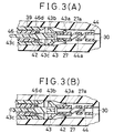
- FIG. 3A is a sectional view of a part of the dispenser, showing the secondary valve located at its closed position;
- FIG. 3B is a sectional view of a part of the dispenser, showing the secondary valve located at its opened position;
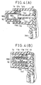
- FIG. 4A is a sectional view of a part of the dispenser, showing the piston located at its initial position; and
- FIG. 4B is a sectional view of a part of the dispenser, showing the piston located in its stroke end.
- As shown in FIG. 1, the
trigger type dispenser 10 comprises aswingable trigger 12, acylinder 14, apiston 16, and anorifice 20. Thecylinder 14 communicates with liquid passages. Thepiston 16 slides back and forth in thecylinder 14 when thetrigger 12 is pulled and released. Theorifice 20 is provided at the distal end of a nozzle. Thetrigger type dispenser 10 can be connected to themouth 18a of acontainer 18. When thepiston 16 slides in thecylinder 14, as thetrigger 12 is operated, liquid is sucked upwards from thecontainer 18 into thecylinder 14, pressurized in thecylinder 14 and forced out from theorifice 20. - The
trigger type dispenser 10 further comprises adispenser body 22 which has a substantially U-shaped cross-section. The distal end of thetrigger 12 is held in the gap between the opposing side walls of thebody 22 such that thetrigger 12 can be swung. Thetrigger 12 is urged toward its initial position, or toward the left in FIG. 1, by areturn spring 24 which is a leaf spring. - As can be seen from FIG. 1, the
dispenser body 22 has avertical cylinder 26 and ahorizontal cylinder 27 which are integral with each other. Thecylinder 14 is integrally formed with thevertical cylinder 26. It extends from thevertical cylinder 26 in parallel to thehorizontal cylinder 27 and is located below thehorizontal cylinder 27. Thevertical cylinder 26 defines a vertical passage (flowing-in passage) 26a, whereas thehorizontal cylinder 27 defines a horizontal passage (flowing-out passage) 27a. Thesepassages hole 30 made in the side wall of thevertical cylinder 26. The flowing-inpassage 26a communicates with thecylinder 14 through anotherhole 32 which is made in the side wall of thevertical cylinder 26. - A hollow
cylindrical valve housing 34 having aflange 34a at its lower end is fitted into the flowing-inpassage 26a from below and, hence, incorporated in thedispenser body 22. Asuction tube 38 is fitted into thevalve housing 34 from below, too. Thevalve housing 34 has an inversely tapered valve seat at its top. The valve seat is located above thesuction tube 38. Mounted on the valve seat is aprimary valve 41. In the present embodiment, theprimary valve 41 is of the type shown in FIGS. 1 and 2 of U.S. Patent No. 4,921,017, which has three blades. - The
valve housing 34 has two coaxial holes, a large hole in its lower half and a small hole in its upper half. The large hole is a diameter much greater than the outer diameter of thesuction tube 38. An annular space is therefore provided between the inner surface of the large hole and thesuction tube 38. The annular space communicates with the interior of thecontainer 18. - As can be clearly understood from FIG. 1, the liquid in the
container 18 is sucked up into thesuction tube 38 when a negative pressure is generated in thecylinder 14. Forcing open theprimary valve 41, the liquid flows from thetube 38 via thehole 32 into thecylinder 14. The liquid in thecylinder 14 is pressurized as thetrigger 12 is pulled, pushing thepiston 16 backward. The liquid further flows into the flowing-outpassage 27a through thehole 30. The liquid is finally forced out from theorifice 20. - The
trigger type dispenser 10 is removably connected to thecontainer 18 by abottle cap 36. More precisely, thebottle cap 36 is mounted on and set in screw engagement with the mouth of thecontainer 18, and theflange 34a of thevalve housing 34 is clamped between thebottle cap 36 and the mouth of thecontainer 18. Thevalve housing 34 has ahole 34b which is usually closed by a packing 35. Thehole 34b can be opened by thetrigger 12 to prevent generation of a negative pressure in thecontainer 18. - A
nozzle 39, which is a bottomed hollow cylinder, is inserted in the flowing-outpassage 27a, i.e., the horizontal passage provided in thedispenser body 22. Thenozzle 39 has ahook 39a on its top. Thehook 39a is so bent that it is fitted in a gap between the top of thedispenser body 22 and thehorizontal cylinder 27. Thenozzle 39 is attached to thedispenser body 22, with thehook 39a set in a holdinghole 22a made in the top wall of thebody 22. The flowing-outpassage 27a comprises a small hole and a large hole which are coaxial with each other. The small hole (i.e., the right half of thepassage 27a) communicates with thecylinder 14, while the large hole (i.e., the left half of thepassage 27a) communicates with theorifice 20. The flowing-outpassage 27a has a stepped portion where the small hole and the large hole meet each other. Asecondary valve 42 is arranged in the flowing-outpassage 27a, positioned in the vicinity of the stepped portion thereof. - A
nozzle cover 40 is connected to thenozzle 39 by ahinge 39b which is integrally formed with thenozzle cover 40. Thenozzle cover 40 is urged onto thenozzle 39, closing theorifice 20, as long as thetrigger type dispenser 10 is not used. To use thedispenser 10, a user rotates thenozzle cover 40 around thehinge 39b into the position indicated by one-dot, one-dash line in FIG. 1. Once set in this position, thenozzle cover 40 has its one part held in the holdinghole 22a of thedispenser body 22 and would not block the stream of liquid coming from theorifice 20. - Like the
secondary valve 42, a spinner 46 (an eddy-flow forming member) is provided in the flowing-outpassage 27a. Thespinner 46 is located at thenozzle 39. Due to its own urging force, thesecondary valve 42 is pressed onto the right end of thespinner 46. Thus, thespinner 46 is pushed onto the proximal end of thenozzle 39 at the back of theorifice 20. - As can be understood from FIG. 2 as well as FIG. 1, the
spinner 46 consists of left and right halves. The left half is a solid cylinder, whereas the right half is a hollow cylinder. The right half hasslits 46a cut in its distal end portion. The left half has ancircular recess 46b and twogrooves 46c, all in its distal end. Thegrooves 46c extend tangent to thecircular recess 46b. Liquid can flow from thecylinder 14 through the right half of thespinner 46, finds its way through theslits 46a, and further flows along thegrooves 46c into thecircular recess 46b. In thecircular recess 46b, the liquid swirls until it flows from theorifice 20 in the form of a spray stream. - The
secondary valve 42 comprises athick plunger 43 and athin plunger 44. Both plungers are made of plastics material. Like thesecondary valve 42, thetrigger 12, thecylinder 14, thepiston 16, thebody 22 and thereturn spring 24, which are other major components of thedispenser 10, are made of plastics material. After the lifetime of thedispenser 10 expires, all components of thedispenser 10 can be melted so that the plastics material may be used again. Thedispenser 10 is advantageous in view of recycle of resources. - The
secondary valve 42 is controlled by a difference between two pressures applied on theplungers thin plunger 44 is fitted in the axial hole made in the right half of thethick plunger 43, such that thethin plunger 44 is axially aligned with thethick plunger 43. Thethick plunger 43 and thethin plunger 44 are placed in the small hole and large hole of the flowing-outpassage 27a, respectively. - The
thick plunger 43 is a hollow cylinder. It has a skirt-shapedseal 43a on the distal end, in which the distal end of thethin plunger 44 is fitted. It has a skirt-shapedseal 43b on other distal end. From other distal end of thethick plunger 43 there extends a rod-shapedvalve body 43c. Thevalve body 43c consists of a thin distal portion and a thick proximal portion and has a stepped portion at the junction of the distal and proximal portions. As shown in FIG. 3A, the stepped portion contacts thevalve seat 46d which is integrally made with thespinner 46. The proximal portion of thevalve body 43c has elongatedgrooves 43c' in its circumferential surface. Thesegrooves 43c' communicate with the axial hole of thethick plunder 43. - The
thin plunger 44 is generally a hollow cylinder and has amiddle spiral portion 44a. Thespiral portion 44a functions as a valve spring. By virtue of the compressing force of thespiral portion 44a, the right end of thethin plunger 44 is pushed onto the periphery of that portion of thedispenser body 22 in which thehole 30 is made, and thevalve body 43c of thethick plunger 43 is pushed onto thevalve seat 46d. That is, thespiral portion 44a of thethin plunger 44 pushes thesecondary valve 42 to the left. - The liquid pressurized in the
cylinder 14 flows via thehole 30 into the right (i.e., the small hole) of the flowing-outpassage 27a. The liquid further flows into the left half (i.e., the thick hole) of thepassage 27a through the axial hole of thethin plunger 44, the axial hole of thethick plunger 43 and theelongated grooves 43c' of thevalve body 43c. As a result, the liquid applies pressures on thesecondary valve 42 from the left and the right. The skirt-shapedseals passage 27a to the left half thereof. - As described above, the left half of the flowing-out
passage 27a has a larger cross section than the right half. Theseal 43b provided in the left half of thepassage 27a has of course a larger diameter than theseal 43a located in the right half of thepassage 27a. Hence, the liquid pressure exerted on theseal 43b from the left is higher than the liquid pressure applied on theseal 43a from the right. Thesecondary valve 42 is thereby urged to the right. - When the difference between the liquid pressures applied on the
secondary valve 42 from the left and the right increases over the compression force of thespiral portion 44a, thevalve body 43c of thesecondary valve 42 slides to the right, away from thevalve seat 46d, against the force of thespiral portion 44a. That is, thesecondary valve 42 is opened. The liquid therefore flows to thespinner 46 through the flowing-outpassage 27a, swirls at thespinner 46, forming an eddy flow, and is forced out from theorifice 20 in the form of a spray stream. The liquid may not be made into an eddy flow at thespinner 46. - In conventional trigger type dispensers, the liquid pressure is applied on the secondary valve from one side only, namely from the cylinder side. If the spring of the secondary valve exerts but an inadequate force, the liquid will flow under a pressure which is lower than desired. If the spring exerts an excessively large force, the user needs to pull the trigger with a large force.
- In the present invention, the liquid pressures are applied on both sides of the
secondary valve 42 to open thevalve 42 by the difference between the pressures. Thesecondary valve 42 is not opened before the liquid in thecylinder 14 is pressurized sufficiently. Hence, the liquid flows from thecylinder 14 to theorifice 20 under a sufficiently high pressure. Although the liquid is highly pressurized, themiddle spiral portion 44a ofthin plunger 44, which functions as the valve spring, need not exert a large force. It is therefore unnecessary for the user to pull thetrigger 12 with a great force in order to apply the liquid in the form of a spray stream. Thetrigger type dispenser 10 is easy to operate, even for persons who are physically feeble. - The
secondary valve 42 may be replaced by another of any different structure, which can be opened and closed in accordance with the difference between the pressures applied on the both sides. For example, thespiral portion 44a ofthin plunger 44, which is used as the valve spring, may be replaced by a sine-wave leaf spring of the type shown in FIG. 1 of U.S. Patent No. 4,273,290 and FIG. 1 of U.S. Patent No.4,989,790 or by a pipe-shaped spring of the type shown in FIG. 4 of U.S. Patent No. 4,365,751. Furthermore, thespiral portion 44a may be replaced by a valve spring which is not integral with thethin plunger 44 and is incorporated in thethin plunger 44. Nonetheless, it is desirable to form thespiral portion 44a (used as the valve spring) integral with thethin plunger 44 as shown in FIG. 2. Thesecondary valve 42 can be assembled more easily than otherwise. - As can be clearly understood, the skirt-shaped seal (small-diameter seal) 43a set in sliding contact in the right half (small hole) of the flowing-out
passage 27a suffices to prevent the liquid from flowing from the right half to the left half of thepassage 27a, along the outer surface of thesecondary valve 42. Theseal 43a may therefore be mounted on thethin plunger 44, not on thethick plunger 43, and may be located on the left to thespiral portion 44a (namely, near the thick plunger 43), as indicated by a one-dot, one-dash line in FIG. 2. - In the present invention, the spring of the
secondary valve 42 can be reinforced by the difference between the pressures applied on thevalve 42 from the left and the right, without increasing the force required to pull thetrigger 12. Hence, the liquid does not dribble from theorifice 20 despite of the pressure (i.e., the residual pressure) of the liquid remaining in thecylinder 14. The present embodiment is designed such that no pressurized liquid is allowed to remain in thecylinder 14. - More precisely, as shown in FIG. 1, the
cylinder 14 is a double-cylinder, having a hollowcylindrical member 14a which protrudes horizontally from thedispenser body 22. Themember 14a communicates with the interior of thecontainer 18 via the gap between thevalve housing 34 and thesuction tube 38. - The
piston 16 comprises apiston body 16a and aseal 16b mounted on thepiston body 16a. Arod 16c is integrally formed with thepiston body 16a. Therod 16c extends such that its distal end is located near thehole 34b made in thevalve housing 34. - The
rod 16c is inserted into thehole 34b when thetrigger 12 is pulled to pressurize the liquid in thecylinder 14 thereby to force out the liquid from theorifice 20. Therod 16c pushes the packing 35, opening thehole 34b. The interior of thecontainer 18 is thereby connected to the atmosphere. Air flows into thecontainer 18, preventing thecontainer 18 from being negatively pressurized. Since theseal 16b is separated from thepiston body 16a, thepiston 16 is easy to produce by molding. - As can be seen from FIGS. 1 and 4, the
seal 16b of thepiston 16 has arecess 16b' for receiving the hollowcylindrical member 14a of thecylinder 14. An outer skirt-shaped seal 17o and an inner skirt-shapedseal 17i are mounted on theseal 16b. The outer skirt-shaped seal 17o is put in sliding contact with the inner circumferential surface of thecylinder 14. The inner skirt-shapedseal 17i is set in sliding contact with the outer circumferential surface of the hollowcylindrical member 14a. As FIG. 1 shows, therecess 16b' of thepiston 16 communicates with the interior of thecontainer 18 through the hollowcylindrical member 14a and the gap between thevalve housing 34 and thesuction tube 38. - The outer skirt-shaped
seal 170 consists of a pair of skirt-shaped seal members which are separated along the axis of thepiston 16. Anannular space 17a is therefore provided among the skirt-shaped seal members and the inner circumferential surface of thecylinder 14. Theseal 16b has alateral hole 17b which opens between the seal members of the outer skirt-shaped seal 17o. Thelateral hole 17b connects theannular space 17a to therecess 16b' of thepiston 16. - In the unit comprised of the
cylinder 14 and thepiston 16, the space between thecylinder 14 and the hollowcylindrical member 14a, i.e., the cylinder chamber (pressurizing chamber) 14b, is partitioned from therecess 16b' of thepiston 16 by the rear (right) seal number 17o' of the outer skirt-shaped seal 17o and the inner skirt-shapedseal 17i. To connect the cylinder chamber 14b to therecess 16b', and escape groove 14c is made in thecylinder 14. - The escape groove 14c is made in the inner surface of the
cylinder 14. It is so positioned that the rear (right) seal member 17o' of the seal 17o slips into it when thetrigger 12 is pulled and swung, pushingpiston 16 almost to the stroke end thereof. Once the rear seal member 17o' slips into the escape groove 14c, the seal member 17o' is released from the sliding contact with thecylinder 14. As a result, the cylinder chamber 14b comes to communicate with therecess 16b' when thepiston 16 reaches a position very close to its stroke end. Since therecess 16b' communicates with the interior of thecontainer 18, the chamber 14b is connected to the interior of thecontainer 18 by therecess 16b'. - Thus, the chamber 14b is connected to the interior of the
container 18 when thepiston 16 is pushed almost to its stroke end. As thepiston 16 approaches its stroke end, it forces the liquid from the cylinder 14 (more precisely, in the chamber 14b) back into thecontainer 18 through therecess 16b'. It should be noted that the liquid remains in thecylinder 14 while thepiston 16 is staying in its pressurizing stroke (i.e., pushed-in stroke). - The liquid, which is pressurized in the
cylinder 14 while thepiston 16 is in its pressurizing stroke, is made to flow from theorifice 20. Otherwise, the liquid is forced back through therecess 16b' into thecontainer 18. No pressurized liquid would therefore remain in thecylinder 14, and no residual pressure is generated in thecylinder 14. Hence, the liquid does not dribble from theorifice 20 and can be efficiently sprayed from theorifice 20. - All the time the
piston 16 stays in its virgin stroke (i.e., initial stroke), thecylinder 14 is filled up with air. Even if the air is compressed, the pressure in thecylinder 14 will not rise to a value great enough to open thesecondary valve 42 to exhaust the air through theorifice 20. As long as air remains in thecylinder 14, no negative pressure can be generated in thecylinder 14. It is therefore difficult to suck the liquid upward into thecylinder 14 from thecontainer 18. - According to the invention, the air escapes into the
container 18 at an early stage of operation. In other words, the air is fast exhausted from thecylinder 14. This is because, as indicated above, the chamber 14b is made to communicate with the interior of thecontainer 18 when thepiston 16 is pushed almost to its stroke end. - The present invention is not limited to the embodiment described above. Various changes and modifications can be made without departing from the scope of the invention.
- As has been described, pressures are applied on the secondary valve from both sides thereof, and the secondary valve is opened by virtue of the difference in the pressures. The secondary valve does not open until the liquid in the cylinder is sufficiently pressurized to a high pressure. Thus, the liquid is sufficiently pressurized when it is force out through the orifice. The spring for the secondary valve need not be strengthened, and the liquid can yet be supplied from the cylinder under a high pressure by pulling the trigger with a comparatively small force.
- Needless to say, the spring of the secondary valve can be reinforced, without increasing the trigger-pulling force beyond a limited range. The liquid can thereby be prevented from dribbling from the orifice in spite of the residual pressure in the cylinder.
- Moreover, the liquid pressurized in the cylinder is either supplied to the orifice or forced back into the container because the cylinder chamber communicates with the interior of the container when the piston is pushed almost to its stroke end. That is, no pressurized liquid remains in the cylinder. No residual pressure exists in the cylinder, whereby the liquid does not dribble from the orifice and is efficiently sprayed therefrom.
- The air filled in the cylinder while the piston stays in the virgin stroke escapes into the container at an early stage of operation. Therefore, the air can be easily exhausted from the chamber.
Claims (6)
- A manually operated trigger type dispenser (10) wherein liquid is sucked up into a cylinder (14), pressurized in the cylinder (14) and supplied from an orifice (20) as a piston (16) reciprocates, as a trigger (12) is pulled and swung, characterized in that:
the cylinder (14) and the orifice (20) is connected by a flowing-out passage (27a) which comprises a small-diameter portion and a large-diameter portion located near the cylinder and the orifice, respectively, and which has a stepped portion at the junction of the small-diameter and large-diameter portions;
a one-way valve (42) is provided in the flowing-out passage (27a) for controlling a flow of the liquid from the cylinder (14) to the orifice (20), and skirt-shaped seals (43a, 43b) are mounted on the one-way valve (42) and set in sliding contact with the inner surface of the flowing-out passage (27a), thereby preventing communication between the small-diameter and large-diameter portions of the flowing-out passage (27a).; and
the one-way valve (42) has a valve body (43), a valve seat (46d) located near the orifice (20) and a valve spring (44a) setting the valve body (43) in contact with valve seat (46d), liquid pressures are applied on the valve body (43) from cylinder side and orifice side, respectively, thereby to move the valve body (43) from the valve seat (46d) against a force of the valve spring (44a) by virtue of a difference between the liquid pressures applied on the valve body (43). - A one-way valve (42) for use in a flowing-out passage of a manually operated trigger type dispenser (10) wherein liquid is sucked up into a cylinder (14), pressurized in the cylinder (14) and supplied from an orifice (20) as a piston (16) reciprocates, as a trigger (12) is pulled and swung, characterized in that:
skirt-shaped seals (43a, 43b) are mounted on the one-way valve (42) and set in sliding contact with the inner surface of the flowing-out passage (27a) which has a stepped portion; and
a valve spring (44a) is integrally formed with a valve body (43), setting the valve body (43) in contact with a valve seat (46d), and the valve body (43) is moved from the valve seat (46d) against a force of the valve spring (44a) by virtue of a difference between liquid pressures applied on the valve body (43) from cylinder side and orifice side, respectively. - The one-way valve according to claim 2, wherein the one-way valve (42) comprises a thick plunger (43) and a thin plunger (44) connected together in axial alignment,
the valve spring (44a) is a spiral portion of the thin plunger (44), and the valve body (43) is a portion of the thick plunger (43);
a large skirt-shaped seal (43b) is mounted on the thick plunger (43) and faces away from the thin plunger (44), and a small skirt-shaped seal (43a) is mounted on the thick plunger (43) and located near the thin plunger (44), or mounted on the thin plunger (44) and located near the thick plunger (43). - A manually operated trigger type dispenser (10) wherein liquid is sucked up into a cylinder (14) through a primary valve (41) provided in a flowing-in passage (26a), pressurized in the cylinder (14) and supplied from an orifice (20) through a secondary valve (42) provided in a flowing-out passage (27a), as a piston (16) reciprocates, as a trigger (12) is pulled and swung against a return spring (24), characterized in that:
the flowing-out passage (27a) connects the cylinder (14) to the orifice (20), comprises a small-diameter portion and a large-diameter portion located near the cylinder and the orifice, respectively,
the secondary valve (42) comprises a hollow cylindrical thick plunger (43) and a hollow cylindrical thin planner (44) which are provided in the large-diameter and small-diameter portions of the flowing-out passage (27a), respectively, and skirt-shaped seals (43a, 43b) which are mounted on the secondary valve (42) and set in sliding contact with the inner surface of the flowing-out passage (27a) thereby preventing communication between small-diameter and large-diameter portions of the flowing-out passage (27a) ; and
the thin plunger (44) has a valve spring (44a) setting the thick plunger (43) in contact with a valve seat (46d) located near the orifice (20), and liquid pressures are applied on the thick plunger (43) from cylinder side and orifice side, respectively, thereby to move the thick plunger (43) from the valve seat (46d) by the virtue of a difference between the liquid pressures applied on the secondary valve (42). - The manually operated trigger type dispenser (10) according to claim 4, wherein the cylinder (14) is a double-cylinder and has a hollow cylindrical member (14a) adapted to communicate with the interior of a container (18),
the piston (16) has a recess (16b') adapted to receive the hollow cylindrical member (14a) and to communicate with the interior of the container (18) through the hollow cylindrical member (14a);
an outer skirt-shaped seal (17o) and an inner skirt-shaped seal (17i) are mounted on the piston (16) and set in sliding contact with the inner surface of the cylinder (14) and the outer surface of the hollow cylinder member (14a), respectively;
the outer skirt-shaped seal (17o) is formed of a pair of outer skirt-shaped seal members which are spaced apart along the piston (16) and which define an annular space (17a) together with the inner surface of the cylinder (14);
the piston (16) has a lateral hole (17b) which opens between the seal members of the outer skirt-shaped seal (17o) and connects the annular space (17a) to the recess (16b') of the piston (16); and
an escape groove (14c) is made in the inner surface of the cylinder (14) and is positioned to receive the rear seal member (17o') of the outer skirt-shaped seal (17o) when the piston (16) is pushed almost to a stroke end, thereby to release the rear seal member (17o') from sliding contact with the cylinder (14). - The trigger type dispenser (10) according to claim 4 or 5, wherein the valve spring (44a) of the secondary valve (42) is a spiral portion of the thin plunger (44), and a portion of the thick plunger (44) is a valve body of the secondary valve (42);
the skirt-shaped seal of the secondary valve (42) comprises a large skirt-shaped seal (43b) which is mounted on the thick plunger (43) and face away from the thin plunger (44), and a small skirt-shaped seal (43a) which is mounted on the thick plunger (43) and located near the thin plunger (44) or mounted on the thin plunger (44) and located near the thick plunger (43).
Applications Claiming Priority (2)
| Application Number | Priority Date | Filing Date | Title |
|---|---|---|---|
| JP246809/94 | 1994-09-16 | ||
| JP6246809A JP2892289B2 (en) | 1994-09-16 | 1994-09-16 | Trigger-type dispenser and one-way valve therefor |
Publications (2)
| Publication Number | Publication Date |
|---|---|
| EP0701950A2 true EP0701950A2 (en) | 1996-03-20 |
| EP0701950A3 EP0701950A3 (en) | 1996-12-27 |
Family
ID=17154011
Family Applications (1)
| Application Number | Title | Priority Date | Filing Date |
|---|---|---|---|
| EP95306527A Withdrawn EP0701950A3 (en) | 1994-09-16 | 1995-09-15 | Hand-operated trigger distributor |
Country Status (4)
| Country | Link |
|---|---|
| US (1) | US5636768A (en) |
| EP (1) | EP0701950A3 (en) |
| JP (1) | JP2892289B2 (en) |
| KR (1) | KR100247846B1 (en) |
Cited By (10)
| Publication number | Priority date | Publication date | Assignee | Title |
|---|---|---|---|---|
| EP0738542A4 (en) * | 1994-10-26 | 1998-01-07 | Yoshino Kogyosho Co Ltd | Trigger type liquid discharge device |
| EP0884110A3 (en) * | 1997-06-10 | 1999-06-23 | S.O.R.I. S.r.l. | Device for delivering fluids contained in bottles, comprising a rigid body and resilient means which are integral with said body and designed to reset the device after delivery |
| WO2000033970A1 (en) * | 1998-12-10 | 2000-06-15 | Afa Polytek B.V. | Precompression system |
| WO2000033969A3 (en) * | 1998-12-10 | 2001-02-08 | Afa Polytek Bv | Dispensing device for a container and method of manufacturing and filling such a container with dosing and/or filling head |
| ES2159994A1 (en) * | 1997-12-31 | 2001-10-16 | Calmar Monturas Sa | Spray pump for liquids. |
| US6364172B1 (en) | 1998-12-10 | 2002-04-02 | Afa Polytek, B.V. | Liquid dispenser and assembly methods therefor |
| AU745856B2 (en) * | 1994-10-26 | 2002-04-11 | Yoshino Kogyosho Co., Ltd. | Trigger type liquid discharge device |
| NL1011479C2 (en) * | 1999-03-06 | 2002-04-23 | Afa Polytek Bv | Water bottle container dispenser has at least one closing member coacting with opening and movable between position closing opening and position leaving clear opening |
| EP1987888A3 (en) * | 2007-04-30 | 2010-06-02 | Ing. Erich Pfeiffer GmbH | Discharge device |
| US10328447B1 (en) | 2018-01-30 | 2019-06-25 | The Procter & Gamble Company | Spray dispenser for liquid dispensing product having a nozzle guard |
Families Citing this family (21)
| Publication number | Priority date | Publication date | Assignee | Title |
|---|---|---|---|---|
| AU750464B2 (en) * | 1994-12-09 | 2002-07-18 | Yoshino Kogyosho Co., Ltd. | Sprayer |
| JP3566368B2 (en) * | 1994-12-09 | 2004-09-15 | 株式会社吉野工業所 | Spring member of trigger sprayer |
| US5715974A (en) * | 1996-10-07 | 1998-02-10 | Contico International, Inc. | Trigger sprayer having central vent cylinder |
| US6244473B1 (en) * | 1999-12-17 | 2001-06-12 | Owens-Illinois Closure Inc. | Pump dispenser having vent valve |
| JP3369523B2 (en) * | 1999-12-27 | 2003-01-20 | 日本ピラー工業株式会社 | Check valve |
| EP1595810A1 (en) * | 2004-05-10 | 2005-11-16 | Createchnic AG | Containers provided with a liner-bag and a one-way-valve |
| US7354008B2 (en) * | 2004-09-24 | 2008-04-08 | Bowles Fluidics Corporation | Fluidic nozzle for trigger spray applications |
| WO2007086156A1 (en) * | 2006-01-26 | 2007-08-02 | Mitani Valve Co., Ltd. | Content discharge mechanism for pump-type container and pump-type product with content discharge mechanism |
| JP4947590B2 (en) * | 2007-06-27 | 2012-06-06 | 株式会社吉野工業所 | Trigger type liquid ejector |
| JP4947591B2 (en) * | 2007-06-29 | 2012-06-06 | 株式会社吉野工業所 | Trigger type liquid ejector |
| US10159997B2 (en) | 2009-11-30 | 2018-12-25 | Silgan Dispensing Systems Corporation | Low cost trigger sprayer |
| USD676760S1 (en) | 2011-03-03 | 2013-02-26 | S.C. Johnson & Son, Inc. | Combined trigger and bottle |
| USD661187S1 (en) | 2011-03-03 | 2012-06-05 | S.C. Johnson & Son, Inc. | Trigger |
| JP2013126646A (en) * | 2011-12-19 | 2013-06-27 | Tetsuya Tada | Spring for trigger, and trigger spray with the same |
| JP6583715B2 (en) | 2015-07-01 | 2019-10-02 | キャニヨン株式会社 | Trigger sprayer |
| JP6634243B2 (en) * | 2015-08-31 | 2020-01-22 | 株式会社吉野工業所 | Trigger type liquid ejector |
| ITUB20159576A1 (en) * | 2015-12-23 | 2017-06-23 | Taplast Srl | DEVICE FOR DELIVERY OF FLUIDS OR MIXTURES |
| ITUB20159355A1 (en) * | 2015-12-23 | 2017-06-23 | Taplast Srl | DEVICE FOR DELIVERY OF FLUIDS OR MIXTURES |
| JP6833361B2 (en) * | 2016-06-24 | 2021-02-24 | キャニヨン株式会社 | Accumulation spray |
| KR102295553B1 (en) | 2020-09-07 | 2021-08-27 | 김재홍 | Fluid Dispenser |
| US11691166B2 (en) * | 2021-08-17 | 2023-07-04 | Silgan Dispensing Systems Corporation | Trigger sprayer venting systems and methods for using the same |
Citations (4)
| Publication number | Priority date | Publication date | Assignee | Title |
|---|---|---|---|---|
| US4273290A (en) | 1977-11-14 | 1981-06-16 | The Afa Corporation | Unitary valve and spring assembly |
| US4365751A (en) | 1980-09-26 | 1982-12-28 | Yoshino Kogyosho Co., Ltd. | Trigger type liquid injector |
| US4921017A (en) | 1988-11-18 | 1990-05-01 | Atsushi Tada | Check valve |
| US4989790A (en) | 1989-12-26 | 1991-02-05 | Afa Products, Inc. | Nozzle cap, spring valve and body assembly |
Family Cites Families (11)
| Publication number | Priority date | Publication date | Assignee | Title |
|---|---|---|---|---|
| US3794213A (en) * | 1972-04-17 | 1974-02-26 | G Schwartzman | Tube mounted applicator |
| NL179791C (en) * | 1977-05-12 | 1986-11-17 | Yoshino Kogyosho Co Ltd | BOTH UPRIGHT AND INVERTED TO USE. |
| US4305530A (en) * | 1978-01-23 | 1981-12-15 | Yoshino Kogyosho Co., Ltd. | Liquid atomizer |
| US4624413A (en) * | 1985-01-23 | 1986-11-25 | Corsette Douglas Frank | Trigger type sprayer |
| US4819835A (en) * | 1986-07-21 | 1989-04-11 | Yoshino Kogyosho Co., Ltd. | Trigger type liquid dispenser |
| DE3928521A1 (en) * | 1989-08-29 | 1991-03-14 | Megaplast Dosiersysteme | DOSING PUMP |
| US5088629A (en) * | 1990-07-30 | 1992-02-18 | Neill Richard K O | Pressure build-up pump sprayer having improved valving means |
| US5385302A (en) * | 1990-10-25 | 1995-01-31 | Contico | Low cost trigger sprayer |
| US5368234A (en) * | 1991-12-13 | 1994-11-29 | Contico International, Inc. | Nozzle assembly for trigger sprayer |
| US5303867A (en) * | 1993-06-24 | 1994-04-19 | The Procter & Gamble Company | Trigger operated fluid dispensing device |
| EP0688608A1 (en) * | 1994-03-25 | 1995-12-27 | GUALA S.p.A. | An atomizer device for manually operated pumps |
-
1994
- 1994-09-16 JP JP6246809A patent/JP2892289B2/en not_active Expired - Lifetime
-
1995
- 1995-09-08 US US08/525,906 patent/US5636768A/en not_active Expired - Fee Related
- 1995-09-13 KR KR1019950029878A patent/KR100247846B1/en not_active Expired - Fee Related
- 1995-09-15 EP EP95306527A patent/EP0701950A3/en not_active Withdrawn
Patent Citations (4)
| Publication number | Priority date | Publication date | Assignee | Title |
|---|---|---|---|---|
| US4273290A (en) | 1977-11-14 | 1981-06-16 | The Afa Corporation | Unitary valve and spring assembly |
| US4365751A (en) | 1980-09-26 | 1982-12-28 | Yoshino Kogyosho Co., Ltd. | Trigger type liquid injector |
| US4921017A (en) | 1988-11-18 | 1990-05-01 | Atsushi Tada | Check valve |
| US4989790A (en) | 1989-12-26 | 1991-02-05 | Afa Products, Inc. | Nozzle cap, spring valve and body assembly |
Cited By (16)
| Publication number | Priority date | Publication date | Assignee | Title |
|---|---|---|---|---|
| EP0738542A4 (en) * | 1994-10-26 | 1998-01-07 | Yoshino Kogyosho Co Ltd | Trigger type liquid discharge device |
| EP1923143A3 (en) * | 1994-10-26 | 2008-08-20 | YOSHINO KOGYOSHO Co., Ltd. | Trigger type liquid discharge device |
| AU745856B2 (en) * | 1994-10-26 | 2002-04-11 | Yoshino Kogyosho Co., Ltd. | Trigger type liquid discharge device |
| EP0884110A3 (en) * | 1997-06-10 | 1999-06-23 | S.O.R.I. S.r.l. | Device for delivering fluids contained in bottles, comprising a rigid body and resilient means which are integral with said body and designed to reset the device after delivery |
| ES2159994A1 (en) * | 1997-12-31 | 2001-10-16 | Calmar Monturas Sa | Spray pump for liquids. |
| CZ300359B6 (en) * | 1998-12-10 | 2009-04-29 | Afa Polytek B. V. | Precompression system, spraying head and atomizing device |
| US6364172B1 (en) | 1998-12-10 | 2002-04-02 | Afa Polytek, B.V. | Liquid dispenser and assembly methods therefor |
| WO2000033969A3 (en) * | 1998-12-10 | 2001-02-08 | Afa Polytek Bv | Dispensing device for a container and method of manufacturing and filling such a container with dosing and/or filling head |
| RU2234379C2 (en) * | 1998-12-10 | 2004-08-20 | Афа Политек Б.В. | Precompression system |
| US6789303B2 (en) | 1998-12-10 | 2004-09-14 | Afa Polytek, B.V. | Liquid dispenser and assembly methods therefor |
| NL1011964C2 (en) * | 1998-12-10 | 2000-11-09 | Afa Polytek Bv | Precompression system for spray dispenser has precompression valve biased to closing position by spring, with space connected to pump and conduit connected to discharge nozzle |
| WO2000033970A1 (en) * | 1998-12-10 | 2000-06-15 | Afa Polytek B.V. | Precompression system |
| NL1011479C2 (en) * | 1999-03-06 | 2002-04-23 | Afa Polytek Bv | Water bottle container dispenser has at least one closing member coacting with opening and movable between position closing opening and position leaving clear opening |
| EP1987888A3 (en) * | 2007-04-30 | 2010-06-02 | Ing. Erich Pfeiffer GmbH | Discharge device |
| US8038036B2 (en) | 2007-04-30 | 2011-10-18 | Ing. Erich Pfeiffer Gmbh | Discharge device |
| US10328447B1 (en) | 2018-01-30 | 2019-06-25 | The Procter & Gamble Company | Spray dispenser for liquid dispensing product having a nozzle guard |
Also Published As
| Publication number | Publication date |
|---|---|
| KR960010090A (en) | 1996-04-20 |
| EP0701950A3 (en) | 1996-12-27 |
| KR100247846B1 (en) | 2000-03-15 |
| JP2892289B2 (en) | 1999-05-17 |
| US5636768A (en) | 1997-06-10 |
| JPH0884945A (en) | 1996-04-02 |
Similar Documents
| Publication | Publication Date | Title |
|---|---|---|
| US5636768A (en) | Manually operated trigger type dispenser | |
| US4735347A (en) | Single puff atomizing pump dispenser | |
| US5509578A (en) | Dispensing pump | |
| JP3177163B2 (en) | No fingertip-operated pump / spray without vents | |
| AU709898B2 (en) | Liquid dispenser with trigger sprayer | |
| JPH05270558A (en) | Manually operated pump for dispensing liquid or creamy substances at a predetermined constant pressure | |
| JPH0263568A (en) | Apparatus for facilitating packing of spray device | |
| EP0484615A1 (en) | Manually operated pump device for dispensing fluids | |
| JP4327307B2 (en) | Medium dispenser | |
| CN100471579C (en) | Fluid Product Dispensing Pumps | |
| US5332128A (en) | Flap valve assembly for trigger sprayer | |
| US6921004B1 (en) | Manually actuated pump assembly | |
| EP1305254B1 (en) | Manually actuated pump assembly | |
| AU715287B2 (en) | Trigger sprayer having central vent cylinder | |
| KR102236452B1 (en) | Container unit | |
| US5697556A (en) | Liquid dispenser having discharge valve assembly | |
| JPH1059405A (en) | Liquid discharge pump | |
| KR100638070B1 (en) | Manual pump assembly | |
| JP2531192Y2 (en) | Spray pump for spray container | |
| JPH02214556A (en) | Manual pressurization type spray head | |
| HK1011313A (en) | Miniature pump sprayer | |
| ZA200209361B (en) | Manually actuated pump assembly. |
Legal Events
| Date | Code | Title | Description |
|---|---|---|---|
| PUAI | Public reference made under article 153(3) epc to a published international application that has entered the european phase |
Free format text: ORIGINAL CODE: 0009012 |
|
| AK | Designated contracting states |
Kind code of ref document: A2 Designated state(s): DE FR GB IT |
|
| PUAL | Search report despatched |
Free format text: ORIGINAL CODE: 0009013 |
|
| AK | Designated contracting states |
Kind code of ref document: A3 Designated state(s): DE FR GB IT |
|
| 17P | Request for examination filed |
Effective date: 19970321 |
|
| 17Q | First examination report despatched |
Effective date: 19970731 |
|
| STAA | Information on the status of an ep patent application or granted ep patent |
Free format text: STATUS: THE APPLICATION IS DEEMED TO BE WITHDRAWN |
|
| 18D | Application deemed to be withdrawn |
Effective date: 19980812 |