RU2234379C2 - Precompression system - Google Patents
Precompression system Download PDFInfo
- Publication number
- RU2234379C2 RU2234379C2 RU2001119062/12A RU2001119062A RU2234379C2 RU 2234379 C2 RU2234379 C2 RU 2234379C2 RU 2001119062/12 A RU2001119062/12 A RU 2001119062/12A RU 2001119062 A RU2001119062 A RU 2001119062A RU 2234379 C2 RU2234379 C2 RU 2234379C2
- Authority
- RU
- Russia
- Prior art keywords
- pump
- compression system
- valve
- channel
- diaphragm
- Prior art date
Links
Images


Classifications
-
- F—MECHANICAL ENGINEERING; LIGHTING; HEATING; WEAPONS; BLASTING
- F04—POSITIVE - DISPLACEMENT MACHINES FOR LIQUIDS; PUMPS FOR LIQUIDS OR ELASTIC FLUIDS
- F04B—POSITIVE-DISPLACEMENT MACHINES FOR LIQUIDS; PUMPS
- F04B9/00—Piston machines or pumps characterised by the driving or driven means to or from their working members
- F04B9/14—Pumps characterised by muscle-power operation
-
- B—PERFORMING OPERATIONS; TRANSPORTING
- B05—SPRAYING OR ATOMISING IN GENERAL; APPLYING FLUENT MATERIALS TO SURFACES, IN GENERAL
- B05B—SPRAYING APPARATUS; ATOMISING APPARATUS; NOZZLES
- B05B11/00—Single-unit hand-held apparatus in which flow of contents is produced by the muscular force of the operator at the moment of use
- B05B11/0005—Components or details
- B05B11/0037—Containers
-
- B—PERFORMING OPERATIONS; TRANSPORTING
- B05—SPRAYING OR ATOMISING IN GENERAL; APPLYING FLUENT MATERIALS TO SURFACES, IN GENERAL
- B05B—SPRAYING APPARATUS; ATOMISING APPARATUS; NOZZLES
- B05B11/00—Single-unit hand-held apparatus in which flow of contents is produced by the muscular force of the operator at the moment of use
- B05B11/0005—Components or details
- B05B11/0062—Outlet valves actuated by the pressure of the fluid to be sprayed
- B05B11/007—Outlet valves actuated by the pressure of the fluid to be sprayed being opened by deformation of a sealing element made of resiliently deformable material, e.g. flaps, skirts, duck-bill valves
-
- B—PERFORMING OPERATIONS; TRANSPORTING
- B05—SPRAYING OR ATOMISING IN GENERAL; APPLYING FLUENT MATERIALS TO SURFACES, IN GENERAL
- B05B—SPRAYING APPARATUS; ATOMISING APPARATUS; NOZZLES
- B05B11/00—Single-unit hand-held apparatus in which flow of contents is produced by the muscular force of the operator at the moment of use
- B05B11/01—Single-unit hand-held apparatus in which flow of contents is produced by the muscular force of the operator at the moment of use characterised by the means producing the flow
- B05B11/10—Pump arrangements for transferring the contents from the container to a pump chamber by a sucking effect and forcing the contents out through the dispensing nozzle
- B05B11/1001—Piston pumps
- B05B11/1009—Piston pumps actuated by a lever
- B05B11/1011—Piston pumps actuated by a lever without substantial movement of the nozzle in the direction of the pressure stroke
-
- B—PERFORMING OPERATIONS; TRANSPORTING
- B05—SPRAYING OR ATOMISING IN GENERAL; APPLYING FLUENT MATERIALS TO SURFACES, IN GENERAL
- B05B—SPRAYING APPARATUS; ATOMISING APPARATUS; NOZZLES
- B05B11/00—Single-unit hand-held apparatus in which flow of contents is produced by the muscular force of the operator at the moment of use
- B05B11/01—Single-unit hand-held apparatus in which flow of contents is produced by the muscular force of the operator at the moment of use characterised by the means producing the flow
- B05B11/10—Pump arrangements for transferring the contents from the container to a pump chamber by a sucking effect and forcing the contents out through the dispensing nozzle
- B05B11/1001—Piston pumps
- B05B11/1015—Piston pumps actuated without substantial movement of the nozzle in the direction of the pressure stroke
-
- B—PERFORMING OPERATIONS; TRANSPORTING
- B05—SPRAYING OR ATOMISING IN GENERAL; APPLYING FLUENT MATERIALS TO SURFACES, IN GENERAL
- B05B—SPRAYING APPARATUS; ATOMISING APPARATUS; NOZZLES
- B05B11/00—Single-unit hand-held apparatus in which flow of contents is produced by the muscular force of the operator at the moment of use
- B05B11/01—Single-unit hand-held apparatus in which flow of contents is produced by the muscular force of the operator at the moment of use characterised by the means producing the flow
- B05B11/10—Pump arrangements for transferring the contents from the container to a pump chamber by a sucking effect and forcing the contents out through the dispensing nozzle
- B05B11/1042—Components or details
- B05B11/1064—Pump inlet and outlet valve elements integrally formed of a deformable material
-
- B—PERFORMING OPERATIONS; TRANSPORTING
- B05—SPRAYING OR ATOMISING IN GENERAL; APPLYING FLUENT MATERIALS TO SURFACES, IN GENERAL
- B05B—SPRAYING APPARATUS; ATOMISING APPARATUS; NOZZLES
- B05B11/00—Single-unit hand-held apparatus in which flow of contents is produced by the muscular force of the operator at the moment of use
- B05B11/01—Single-unit hand-held apparatus in which flow of contents is produced by the muscular force of the operator at the moment of use characterised by the means producing the flow
- B05B11/10—Pump arrangements for transferring the contents from the container to a pump chamber by a sucking effect and forcing the contents out through the dispensing nozzle
- B05B11/1042—Components or details
- B05B11/1066—Pump inlet valves
- B05B11/1067—Pump inlet valves actuated by pressure
-
- B—PERFORMING OPERATIONS; TRANSPORTING
- B05—SPRAYING OR ATOMISING IN GENERAL; APPLYING FLUENT MATERIALS TO SURFACES, IN GENERAL
- B05B—SPRAYING APPARATUS; ATOMISING APPARATUS; NOZZLES
- B05B11/00—Single-unit hand-held apparatus in which flow of contents is produced by the muscular force of the operator at the moment of use
- B05B11/01—Single-unit hand-held apparatus in which flow of contents is produced by the muscular force of the operator at the moment of use characterised by the means producing the flow
- B05B11/10—Pump arrangements for transferring the contents from the container to a pump chamber by a sucking effect and forcing the contents out through the dispensing nozzle
- B05B11/1042—Components or details
- B05B11/1073—Springs
- B05B11/1074—Springs located outside pump chambers
-
- B—PERFORMING OPERATIONS; TRANSPORTING
- B05—SPRAYING OR ATOMISING IN GENERAL; APPLYING FLUENT MATERIALS TO SURFACES, IN GENERAL
- B05B—SPRAYING APPARATUS; ATOMISING APPARATUS; NOZZLES
- B05B11/00—Single-unit hand-held apparatus in which flow of contents is produced by the muscular force of the operator at the moment of use
- B05B11/01—Single-unit hand-held apparatus in which flow of contents is produced by the muscular force of the operator at the moment of use characterised by the means producing the flow
- B05B11/10—Pump arrangements for transferring the contents from the container to a pump chamber by a sucking effect and forcing the contents out through the dispensing nozzle
- B05B11/1042—Components or details
- B05B11/1073—Springs
- B05B11/1077—Springs characterised by a particular shape or material
-
- B—PERFORMING OPERATIONS; TRANSPORTING
- B05—SPRAYING OR ATOMISING IN GENERAL; APPLYING FLUENT MATERIALS TO SURFACES, IN GENERAL
- B05B—SPRAYING APPARATUS; ATOMISING APPARATUS; NOZZLES
- B05B11/00—Single-unit hand-held apparatus in which flow of contents is produced by the muscular force of the operator at the moment of use
- B05B11/0005—Components or details
- B05B11/0097—Means for filling or refilling the sprayer
Landscapes
- Engineering & Computer Science (AREA)
- Mechanical Engineering (AREA)
- General Engineering & Computer Science (AREA)
- Containers And Packaging Bodies Having A Special Means To Remove Contents (AREA)
- Closures For Containers (AREA)
- Reciprocating Pumps (AREA)
- Compressor (AREA)
- Nozzles (AREA)
Abstract
Description
Данное изобретение относится к системе предварительного сжатия, установленной между насосом и распылительным соплом, которые соединены каналом, выходящим в пространство, при этом система содержит клапан предварительного сжатия, выполненный с возможностью перемещения между положением, запирающим соединение, в котором он примыкает к опорной поверхности в устье канала и положением, открывающим соединение, в котором он отходит от опорной поверхности, при этом клапан предварительного сжатия смещается в запирающее положение с помощью пружинного средства. Такая система предварительного сжатия известна из патента США №5 730 335.This invention relates to a pre-compression system installed between the pump and the spray nozzle, which are connected by a channel extending into the space, the system includes a pre-compression valve made with the possibility of movement between the position locking the connection in which it is adjacent to the supporting surface at the mouth channel and the position that opens the connection in which it moves away from the supporting surface, while the pre-compression valve is shifted to the locking position by means of a spring other means. Such a precompression system is known from US Pat. No. 5,730,335.
Известная система предварительного сжатия применяется в распылительной насадке для емкости, например для бутылки с жидким моющим средством. Эту распылительную насадку выполняют в виде корпуса, в котором размещен приводимый вручную поршневой насос. Этот насос приводится в действие пусковым устройством, шарнирно соединенным с корпусом. Сторона всасывания насоса соединена с трубкой, проходящей в бутылку на существенную длину, обычно вблизи ее дна, и через которую жидкость можно извлекать из бутылки. Сторона нагнетания насоса соединена с выпускным соплом распылительной насадки посредством канала. Между насосом и каналом, проходящим в выпускное сопло, размещена система предварительного сжатия, содержащая клапан предварительного сжатия, удерживаемый в закрытом положении пружинным средством и открываемым только при достижении заранее определенного давления в насосе. Клапан предварительного сжатия предназначен для того, чтобы текучая среда не могла выйти из выпускного сопла при слишком низком давлении, что привело бы с образованию в распылении слишком крупных капель. Для обеспечения оптимального режима распыления жидкость должна выходить из выпускного сопла под воздействием заранее определенного и относительно высокого давления.The known pre-compression system is used in a spray nozzle for a container, for example for a bottle with liquid detergent. This spray nozzle is made in the form of a housing in which a manually driven piston pump is placed. This pump is driven by a starter pivotally connected to the housing. The suction side of the pump is connected to a tube extending into the bottle for a substantial length, usually near its bottom, and through which liquid can be removed from the bottle. The discharge side of the pump is connected to the outlet nozzle of the spray nozzle via a channel. Between the pump and the channel passing into the exhaust nozzle, there is a pre-compression system comprising a pre-compression valve held in closed position by spring means and opened only when a predetermined pressure in the pump is reached. The pre-compression valve is designed to prevent the fluid from escaping from the outlet nozzle at too low a pressure, which would result in the formation of droplets that are too large to spray. To ensure optimal spraying, the liquid must exit the outlet nozzle under the influence of a predetermined and relatively high pressure.
Известная система предварительного сжатия содержит концевую часть цилиндрической стенки насоса, которая выходит в кольцевое пространство. Обод цилиндрической стенки образует опорную поверхность, к которой прижимается упруго гибкая диафрагма. Эта диафрагма прижимается в закрывающее положение за счет давления пружины, которое в диафрагме указанного патента создается напряжениями изгиба в материале самой диафрагмы. Когда давление в цилиндре насоса становится достаточно высоким, диафрагма поднимется с опорной поверхности, в результате чего жидкость под давлением может проходить из цилиндра в канал, ведущий в выпускное сопло. Когда почти вся жидкость будет под давлением удалена из цилиндра и давление снова понизится, диафрагма вернется в закрывающее положение, в котором она снова будет прижиматься к опорной поверхности в результате внутреннего усилия пружины.The known pre-compression system comprises an end portion of the cylindrical wall of the pump, which enters the annular space. The rim of the cylindrical wall forms a supporting surface against which an elastically flexible diaphragm is pressed. This diaphragm is pressed into the closing position due to the pressure of the spring, which is created in the diaphragm of the said patent by bending stresses in the material of the diaphragm itself. When the pressure in the pump cylinder becomes sufficiently high, the diaphragm rises from the support surface, as a result of which liquid under pressure can pass from the cylinder into the channel leading to the outlet nozzle. When almost all the liquid is removed from the cylinder under pressure and the pressure drops again, the diaphragm will return to the closing position, in which it will again be pressed against the supporting surface as a result of the internal spring force.
Однако известная система предварительного сжатия имеет недостаток, заключающийся в том, что кольцевое пространство центрируется с цилиндром насоса. Поэтому трудно конструировать эту известную систему предварительного сжатия таким образом, чтобы ее можно было изготовить с помощью литьевого формования, поэтому полученная конструкция становится относительно громоздкой, в результате чего затрудняется ее выполнение в компактной распылительной насадке. В указанном патенте США №5 730 335 насос, содержащий систему предварительного сжатия, по производственным соображениям выполнен под углом между трубкой всасывания и трубкой распыления, что приводит к сложной конструкции, трудной в сборке.However, the known pre-compression system has the disadvantage that the annular space is centered with the pump cylinder. Therefore, it is difficult to design this known pre-compression system in such a way that it can be manufactured by injection molding, therefore, the resulting structure becomes relatively cumbersome, making it difficult to implement it in a compact spray nozzle. In said U.S. Patent No. 5,730,335, a pump containing a pre-compression system is, for manufacturing reasons, made at an angle between the suction pipe and the spray pipe, which leads to a complex structure that is difficult to assemble.
Поэтому задача данного изобретения заключается в создании системы предварительного сжатия описываемого выше типа, изготовление и сборка которой будет легче, чем известной системы предварительного сжатия, которая обеспечит возможность более свободного конструирования при выполнении ее в компактной распылительной насадке. Согласно изобретению эта задача решается за счет того, что пространство соединяется с насосом и канал соединен с выпускным соплом. Изменяя таким образом направление потока на обратное по сравнению с известными системами предварительного сжатия, получают систему предварительного сжатия, которую не нужно центрировать с цилиндром насоса, но которая может, например, быть размещена рядом с цилиндром. Таким образом, конструкцию распылительной насадки можно существенно упростить, сделать насадку более компактной и простой и более технологичной. Причем в результате этого не нужно будет размещать цилиндр и поршень под углом, что является преимуществом для самой работы устройства.Therefore, the object of the present invention is to provide a precompression system of the type described above, the manufacture and assembly of which will be easier than the known precompression system, which will allow more free construction when executed in a compact spray nozzle. According to the invention, this problem is solved due to the fact that the space is connected to the pump and the channel is connected to the exhaust nozzle. By thus reversing the direction of flow compared with the known pre-compression systems, a pre-compression system is obtained which does not need to be centered with the pump cylinder, but which, for example, can be placed next to the cylinder. Thus, the design of the spray nozzle can be greatly simplified, to make the nozzle more compact and simple and more technological. Moreover, as a result of this, it will not be necessary to place the cylinder and piston at an angle, which is an advantage for the operation of the device itself.
Пружинное средство предпочтительно выполнено заодно с клапаном предварительного сжатия, например клапан предварительного сжатия и пружинное средство образованы упруго изгибаемой диафрагмой. За счет этого может быть получен конструкционно простой клапан. Диафрагма предпочтительно имеет куполообразную форму и поэтому имеет устойчивое и в соответствующей степени напряженное положение в нерабочем состоянии.The spring means is preferably integral with the pre-compression valve, for example, the pre-compression valve and the spring means are formed by an elastically bent diaphragm. Due to this, a structurally simple valve can be obtained. The diaphragm preferably has a dome-shaped shape and therefore has a stable and to an appropriate degree tense position when inoperative.
Система предварительного сжатия предпочтительно содержит стопорный элемент, взаимодействующий с диафрагмой, поэтому изгиб диафрагмы ограничен, и исключается возможность того, что диафрагма “перевернется” в другое устойчивое положение на большем расстоянии от опорной поверхности, из которого она потом не вернется. Стопорный элемент предпочтительно выполнен заодно с диафрагмой.The pre-compression system preferably contains a locking element that interacts with the diaphragm, so the bending of the diaphragm is limited, and the possibility that the diaphragm “flips” to another stable position at a greater distance from the supporting surface, from which it will not later return, is eliminated. The locking element is preferably integral with the diaphragm.
Кроме того, пространство является предпочтительно, по меньшей мере частично, кольцевым и, по меньшей мере частично, окружает конец канала, поэтому можно применять простую круглую диафрагму. И та часть канала, которая окружена кольцевым пространством, и насос могут иметь центровую линию; при этом эти центровые линии по существу параллельны, но смещены относительно друг друга.In addition, the space is preferably at least partially annular and at least partially surrounds the end of the channel, so a simple circular diaphragm can be used. And that part of the channel, which is surrounded by an annular space, and the pump can have a center line; however, these center lines are essentially parallel, but offset relative to each other.
Кольцевое пространство предпочтительно ограничено по существу цилиндрической гильзой. В этом случае обеспечивается надлежащее уплотнение и может быть исключена утечка. Диафрагма и гильза могут быть выполнены заодно, тем самым в еще большей степени сократив число деталей и упростив сборку системы.The annular space is preferably limited by a substantially cylindrical sleeve. In this case, proper sealing is ensured and leakage can be eliminated. The diaphragm and sleeve can be made at the same time, thereby further reducing the number of parts and simplifying the assembly of the system.
По меньшей мере одно отверстие всасывания, запираемое клапаном, выполнено в гильзе для втягивания распыляемой жидкости. Если отсечной клапан выполнен заодно с гильзой, то число отдельных деталей сократится в еще большей степени, и сборка системы предварительного сжатия еще более упроститься.At least one suction opening, closed by a valve, is made in a sleeve for drawing in the sprayed liquid. If the shut-off valve is integral with the sleeve, the number of individual parts will be reduced even more, and the assembly of the pre-compression system will be further simplified.
Изобретение также относится к распылительному устройству, содержащему насос, имеющий сторону всасывания и сторону нагнетания, средство, соединенное со стороной всасывания насоса, для подачи распыляемой жидкости, выпускное сопло, соединенное со стороной нагнетания насоса, и систему предварительного сжатия между насосом и выпускным соплом.The invention also relates to a spray device comprising a pump having a suction side and a discharge side, means connected to a suction side of a pump for supplying a spray liquid, an outlet nozzle connected to a discharge side of the pump, and a pre-compression system between the pump and the outlet nozzle.
Наконец, данное изобретение относится к узлу, образованному емкостью и описываемым выше распылительным устройством.Finally, the present invention relates to an assembly formed by a container and the spray device described above.
Изобретение иллюстрируется на примере, со ссылкой на прилагаемые чертежи, на которых:The invention is illustrated by example, with reference to the accompanying drawings, in which:
фиг.1 - изображение в перспективе узла, образуемого емкостью и распылительным устройством, в котором может использоваться система предварительного сжатия согласно изобретению;FIG. 1 is a perspective view of an assembly formed by a container and a spray device in which the pre-compression system according to the invention can be used;
фиг.2 - изображение в перспективе с пространственным разделением деталей распылительной насадки показанного на фиг.1 узла, содержащего систему предварительного сжатия;figure 2 is a perspective view with a spatial separation of the details of the spray nozzle shown in figure 1 node containing the pre-compression system;
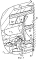
фиг.3 - частичное сечение изображения в перспективе показанной на фиг.2 распылительной насадки во время хода нагнетания;figure 3 is a partial cross-sectional image in perspective shown in figure 2 of the spray nozzle during the discharge stroke;
фиг.4 - вид, соответствующий показанной на фиг.3 распылительной насадке во время обратного хода;FIG. 4 is a view corresponding to the spray nozzle shown in FIG. 3 during a return stroke; FIG.
фиг.5 - подробное изображение системы предварительного сжатия в направлении стрелки V на фиг.3;5 is a detailed image of the pre-compression system in the direction of arrow V in FIG. 3;
фиг.6А и 6В - продольные сечения системы предварительного сжатия в начале и конце хода нагнетания соответственно иfiga and 6B are longitudinal sections of the pre-compression system at the beginning and end of the discharge stroke, respectively, and
фиг.7 - схематическое подробное изображение в перспективе альтернативного варианта выполнения клапана, используемого в системе предварительного сжатия;7 is a schematic detailed perspective view of an alternative embodiment of a valve used in a precompression system;
фиг.8 - продольное сечение альтернативного варианта выполнения системы предварительного сжатия иFig. 8 is a longitudinal section through an alternative embodiment of a precompression system; and
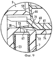
фиг.9 - подробное изображение данного варианта реализации системы предварительного сжатия.Fig.9 is a detailed image of this embodiment of a pre-compression system.
Распылительная насадка 1 для емкости 2 содержит насос 3, имеющий сторону 5 всасывания и сторону 6 нагнетания. Подвижное функциональное средство 4 соединено с насосом 3; в иллюстрируемом примере оно состоит из пускового устройства 13, имеющего сплошной поворотный вал 53, который входит в полое пространство 54 в раме 22, на которой размещен насос 3, и который фиксируется в нем гибким защелкиваемым рычагом 55.The spray nozzle 1 for tank 2 comprises a pump 3 having a
Средство 7 соединено со стороной 5 всасывания насоса 3 для подачи текучей среды из емкости, включающее канал, свободный конец которого соединен с трубкой 23, проходящей в емкость. Сторона нагнетания 6 насоса 3 соединена с выпускным соплом 8 через канал 9.The
Так как вал 53 пускового устройства 13 и пространство 54 расположены над распылительным каналом 9, отверстие 56 выполнено в пусковом устройстве 13, через которое проходит конец этого канала 9, на котором выполнено выпускное сопло 8.Since the
Насос 3 является поршневым насосом, состоящим из корпуса или цилиндра 10 насоса и поршня 11, совершающего в нем возвратно-поступательные движения. Поршень 11 соединен с пусковым устройством 13. Для возврата поршня 11 и пускового устройства 13 в их свободное нерабочее положение в конце хода насоса распылительная насадка 1 содержит средство 16 смещения. В иллюстрируемом варианте выполнения это средство смещения образовано парой параллельных пружин 17 изгиба, которые зацепляют ребра внутри пускового устройства 13. Когда пусковое устройство 13 поворачивается вокруг поворотного вала в сторону насоса 3 и вдавливает поршень 11 в цилиндр 10 во время хода нагнетания, пружины 17 сгибаются. После прекращения действия давления на пусковое устройство 13 оно отжимается назад в свое нерабочее положение пружинами 17, отгибающимися назад. Поскольку пусковое устройство соединено с поршнем 11, чтобы оставаться в фиксированном положении при растяжении и при сжатии, поршень 11 затем также возвращается в свое нерабочее положение. Соединение между пусковым устройством 13 и поршнем 11 является защелкиваемым соединением, образованным выступами 14 пускового устройства 13, которые защелкиваются в соответствующие отверстия 28 в поршне 11.The pump 3 is a piston pump, consisting of a housing or
Между цилиндром 10 и распылительным каналом 9 размещена система предварительного сжатия, включающая пространство 58, являющееся кольцевым в иллюстрируемом варианте выполнения, соединенное с цилиндром 10 и концевой частью выходящего в него распылительного канала 9, которые герметизированы относительно газа и жидкости с помощью упруго гибкой диафрагмы 59. Пространство 58 ограничено цилиндрической гильзой 60, которая входит в полость 61 в раме 22 и выполнена заодно с диафрагмой 59 в иллюстрируемом варианте выполнения. В этой цилиндрической гильзе 60 выполнено отверстие 15, в котором размещен клапан и которое соединено с трубкой всасывания 7 для текучей среды через отверстие 67 в раме 22. Этот клапан 63, который также выполнен заодно с гильзой 60, выполнен подвижным, в иллюстрируемом варианте выполнения он шарнирно подвижен между положением, в котором он герметично запирает отверстие 67 (фиг.3, 4, 6А), и положением, в котором это отверстие 67 остается свободным (фиг.5, 6В). При этом стопорный элемент 64 соединен с диафрагмой 59 и служит для ограничения изгиба диафрагмы 59 и для предотвращения ее “переворачивания”. Цилиндрическая гильза 60 фиксируется в полости 61 рамы 22 с помощью концевой стенки, которая в иллюстрируемом варианте выполнения выполнена заодно с емкостью 2. Цилиндрическая гильза 60 также включает усиливающий фланец 75, благодаря которому исключается деформация гильзы 60 под воздействием давления нагнетания в цилиндре 10 и поэтому исключается риск утечки вдоль гильзы 60.Between the
В предпочтительном варианте выполнения (фиг.7) отсечной клапан 63 соединен с цилиндрической гильзой 60 посредством пары шарнирных и растягивающихся f-образных рычагов 68, один конец 69 которых прикреплен к гильзе 60, а другой конец соединен с корпусом 63 клапана. Во время возвратного хода или хода всасывания насоса 11 рычаги 68 поворачиваются вверх и слегка растягиваются, в результате чего корпус 63 клапана поднимается из отверстия 67 на высоту L.In the preferred embodiment (Fig. 7), the shut-off
В еще одном варианте реализации (фиг.8) цилиндрическая гильза 60 не содержит отверстие, которое соединено с трубкой 23 всасывания. Вместо этого гильза 60 имеет периферийную краевую часть 70, которая незначительно выступает наружу и тесно примыкает к стенке полости 61. Периферийная краевая часть 70 относительно гибкая и включает слегка наклонную внутреннюю поверхность 73. Гильза 60 также содержит часть 71, имеющую уменьшенный диаметр и ограниченную с одной стороны гибкой краевой частью 70 и с другой стороны цилиндрической частью гильзы 60. Вместе со стенкой полости 61 имеющая уменьшенный диаметр часть 71 определяет кольцевое пространство 72, которое находится в соединении по текучей среде с отверстием 67.In yet another embodiment (FIG. 8), the
Во время нагнетательного хода поршня 11 давление текучей среды, действующее на наклонную внутреннюю поверхность 73 периферийной краевой части 70, будет оказывать на эту часть направленное внутрь усилие в направлении стенки полости 61, благодаря чему будет создаваться хорошее уплотнение по всей периферии полости 61. С другой стороны, всасывающее усилие за поршнем 11 во время возвратного хода или хода всасывания и атмосферное давление в емкости 2 создают перепад давлений на периферийной краевой части 70, оказывая на нее направленное внутрь усилие, в сторону от стенки, и создавая сообщение по текучей среде между кольцевым пространством 72, непосредственно соединенным с внутренним пространством емкости 2 через трубку всасывания, и цилиндром 10.During the delivery stroke of the
Таким образом, периферийная краевая часть 70 функционирует как клапан, имеющий хорошие герметизирующие свойства. Благодаря герметизирующему действию периферийной краевой части 70 давление нагнетания не воздействует на цилиндрическую часть гильзы 60, в результате чего снижается риск утечки текучей среды вдоль цилиндрической части и соединенными с ней кольцевыми уплотняющими ребрами 74. Помимо этого, гильзу 60 можно выполнить меньших размеров и с меньшим весом, чем в предыдущих вариантах выполнения, поскольку нет необходимости усиливать фланец вдоль периферийного края. Гильзу 60 согласно этому варианту выполнения можно изготовить простым литьевым формованием, поскольку в результате исключения отверстия в боковой стенке и соответствующего клапана теперь нет необходимости использовать оправки или пресс-штоки в пресс-формах. Наконец, также обеспечивается возможность более легкой установки гильзы 60, поскольку она полностью симметрична в направлении поворота вокруг центровой линии и не имеет отверстия, которое нужно было бы центрировать с отверстием 67.Thus, the
Точная форма периферийной краевой части 70 гильзы 60 не имеет особого значения, поскольку единственное требование заключается в том, чтобы она оказывала достаточное давление на стенку полости 61 для обеспечения необходимой герметизации во время нагнетательного хода и чтобы она поднималась от стенки в любой точке по своему периметру во время хода всасывания. Необходимо подбирать формы краевой части 70 и стенки такими, чтобы они определяли кольцевое пространство. Поэтому угол наклона периферийной краевой части в этом варианте выполнения (фиг.9) несколько меньший, поскольку стенка полости имеет большую наклонную часть, создавая при этом по существу тот же объем для кольцевого пространства 72.The exact shape of the
Система 40 предварительного сжатия используется известным образом для исключения перемещения текучей среды из емкости 2 в распылительное сопло, пока не будет достигнуто заранее определенное давление нагнетания. Если текучая среда распыляется через сопло 8 при слишком низком давлении, то она не будет распыляться в достаточной степени, и капли, создаваемые в конусе распыления, будут достаточно крупными. Чтобы это исключить, соединение между емкостью 2 и распылительным соплом 8 закрывают диафрагмой 59, которую принудительно прижимают к ободу 66 распылительного канала 9, служащего опорной поверхностью, под воздействием внутреннего напряжения, определяемого куполообразной конфигурацией и усиливаемого достигаемым давлением позади диафрагмы 59. Диафрагма 59 будет поднята с опорной поверхности 66 только при достижении достаточного давления в цилиндре 10 при перемещении поршня 11 в его конечное положение, например давления порядка 0/3 МПа.The
Распылительная насадка 1 функционирует следующим образом. Если пользователю нужно распылить текучую среду из емкости 2, сначала он оттягивает рукоятку 13. При этом воздух, присутствующий в цилиндре 10 и который не может попасть назад в емкость 2 из-за того, что отверстие 67 закрыто клапаном 63, сжимается поршнем 11. Когда давление воздуха достаточно высокое в конце хода нагнетания, тогда диафрагма 59 поднимается с опорной поверхности 66, поэтому воздух может выходить.The spray nozzle 1 operates as follows. If the user needs to spray the fluid from the container 2, first he pulls the
Во время последующего возвратного хода, обеспечиваемого средством 16 смещения текучая среда вытягивается из емкости 2 по трубке 23, проходу 7 и отверстиям 62, 67 в цилиндр 10 до полного наполнения его в конце возвратного хода или хода всасывания (фиг.6А). Чтобы исключить возникновение частичного вакуума в емкости 2 во время этого хода в стенке цилиндра 10 выполнено отверстие аэрации 51, которое открывается, когда внешняя периферийная уплотняющая кромка 39В проходит отверстие 51 во время перемещения внутрь поршня 11, и которое снова соединяется с замкнутым пространством, ограниченным между внешней и внутренней периферийными уплотняющими кромками 39В и 39А поршня 11, во время наружного хода поршня 11.During the subsequent return stroke provided by the biasing means 16, the fluid is drawn from the container 2 through the
При повторном втягивании пускового устройства 13 давление в цилиндре 10 очень быстро возрастает, поскольку текучая среда не поддается сжатию. При этом диафрагма 59 поднимается с опорной поверхности 66 по существу мгновенно, и текучую среду можно выдавить через пространство между диафрагмой 59 и опорной поверхностью 66 в распылительный канал 9, и затем в распылительное сопло 8 (фиг.6В), где она распыляется.When the
Поскольку согласно изобретению кольцевое пространство 58 соединено с цилиндром 10 насоса и выходящий в него канал 9 соединен с распылительным соплом, а не наоборот, как в обычных системах предварительного сжатия, поэтому кольцевое пространство 58 не нужно центрировать с цилиндром 10, и оно может быть, согласно соответствующему изображению на чертежах, смещенным. Поэтому имеется возможность эффективно изготавливать распылительную насадку литьевым формованием с обеспечением компактной конструкции.Since, according to the invention, the
Несмотря на то что изобретение поясняется на примере варианта его выполнения, очевидно, что оно им не ограничивается. Например, диафрагму и гильзу можно выполнять отдельно. Также стопорный элемент в некоторых случаях можно не предусматривать, и, разумеется, подбор материалов может быть разным. Объем данного изобретения поэтому определяется только прилагаемой формулой изобретения.Despite the fact that the invention is illustrated by the example of a variant of its implementation, it is obvious that it is not limited to them. For example, the diaphragm and sleeve can be performed separately. Also, in some cases, the locking element may not be provided, and, of course, the selection of materials may be different. The scope of this invention is therefore determined only by the attached claims.
Claims (11)
Applications Claiming Priority (4)
| Application Number | Priority Date | Filing Date | Title |
|---|---|---|---|
| NL1010778 | 1998-12-10 | ||
| NL1010778 | 1998-12-10 | ||
| NL1011964A NL1011964C2 (en) | 1998-12-10 | 1999-05-05 | Precompression system for spray dispenser has precompression valve biased to closing position by spring, with space connected to pump and conduit connected to discharge nozzle |
| NL1011964 | 1999-05-05 |
Publications (2)
| Publication Number | Publication Date |
|---|---|
| RU2001119062A RU2001119062A (en) | 2003-06-27 |
| RU2234379C2 true RU2234379C2 (en) | 2004-08-20 |
Family
ID=26642890
Family Applications (1)
| Application Number | Title | Priority Date | Filing Date |
|---|---|---|---|
| RU2001119062/12A RU2234379C2 (en) | 1998-12-10 | 1999-12-10 | Precompression system |
Country Status (22)
| Country | Link |
|---|---|
| EP (1) | EP1137493B1 (en) |
| JP (1) | JP4344098B2 (en) |
| KR (1) | KR100594330B1 (en) |
| CN (1) | CN1133505C (en) |
| AR (1) | AR025161A1 (en) |
| AT (1) | ATE261778T1 (en) |
| AU (1) | AU1897200A (en) |
| BR (1) | BR9916110A (en) |
| CA (1) | CA2354125C (en) |
| CO (1) | CO5290343A1 (en) |
| CZ (1) | CZ300359B6 (en) |
| DE (1) | DE69915677T2 (en) |
| DK (1) | DK1137493T3 (en) |
| ES (1) | ES2216612T3 (en) |
| HK (1) | HK1042065B (en) |
| HU (1) | HU225004B1 (en) |
| NL (1) | NL1011964C2 (en) |
| PL (1) | PL193250B1 (en) |
| PT (1) | PT1137493E (en) |
| RU (1) | RU2234379C2 (en) |
| SK (1) | SK286478B6 (en) |
| WO (1) | WO2000033970A1 (en) |
Cited By (3)
| Publication number | Priority date | Publication date | Assignee | Title |
|---|---|---|---|---|
| RU2549860C2 (en) * | 2010-11-22 | 2015-04-27 | Гуала Диспенсинг С.П.А. | Trigger-type proportioner |
| RU2553298C2 (en) * | 2010-09-16 | 2015-06-10 | Гуала Диспенсинг С.П.А. | Trigger-type proportioner |
| RU2614032C2 (en) * | 2012-07-17 | 2017-03-22 | Гуала Диспенсинг С.П.А. | Trigger dispenser |
Families Citing this family (18)
| Publication number | Priority date | Publication date | Assignee | Title |
|---|---|---|---|---|
| US6364172B1 (en) | 1998-12-10 | 2002-04-02 | Afa Polytek, B.V. | Liquid dispenser and assembly methods therefor |
| EP1407825A1 (en) | 2002-10-10 | 2004-04-14 | Monsanto Europe S.A. | New spray bottle |
| PL206757B1 (en) | 2002-10-10 | 2010-09-30 | Monsanto Europe Sa | New spray bottle |
| PT1586383E (en) * | 2004-04-15 | 2007-02-28 | Monsanto Europe Sa | Liquid dispensing device |
| NL1028577C2 (en) | 2005-03-21 | 2006-09-25 | Afa Polytek Bv | Dosing head for dispensing fluid from a container. |
| PL1974826T3 (en) * | 2007-03-24 | 2016-04-29 | Afa Polytek Bv | Liquid dispensing device with a diaphragm valve method of assembling the valve |
| IT1399592B1 (en) | 2010-04-14 | 2013-04-26 | Guala Dispensing Spa | SPROCKET DISPENSER FOR LIQUIDS WITH STOPPER FOR THE DELIVERY VALVE. |
| ITBS20100080A1 (en) * | 2010-04-14 | 2011-10-15 | Guala Dispensing Spa | GRILLER DISPENSER FOR LIQUIDS WITH DELIVERY VALVE |
| ITBS20100081A1 (en) * | 2010-04-14 | 2011-10-15 | Guala Dispensing Spa | GRILLER DISPENSER FOR LIQUIDS WITH ELASTIC RETURN ELEMENT |
| IT1399591B1 (en) * | 2010-04-14 | 2013-04-26 | Guala Dispensing Spa | GRILLER DISPENSER FOR LIQUIDS WITH HEAD VALVES. |
| IT1399593B1 (en) | 2010-04-14 | 2013-04-26 | Guala Dispensing Spa | GRILLER DISPENSER FOR LIQUIDS WITH INTAKE VALVE. |
| IT1403860B1 (en) * | 2011-02-16 | 2013-11-08 | Guala Dispensing Spa | TRIGGER SUPPLY DEVICE WITH DELIVERY VALVE |
| ES2557133T3 (en) * | 2011-02-16 | 2016-01-22 | Guala Dispensing S.P.A. | Trigger dispensing device with a supply valve |
| GB201110250D0 (en) | 2011-06-16 | 2011-08-03 | Obrist Closures Switzerland | A trigger pump dispenser |
| ITBS20120116A1 (en) * | 2012-07-24 | 2014-01-25 | Guala Dispensing Spa | TRIGGER SUPPLY DEVICE |
| CN105642470A (en) * | 2015-12-25 | 2016-06-08 | 中山市美捷时包装制品有限公司 | Gun pump capable of being used at multiple angles |
| USD878207S1 (en) | 2017-07-24 | 2020-03-17 | Obrist Closures Switzerland Gmbh | Spraying device for bottles |
| WO2021079387A1 (en) * | 2019-10-25 | 2021-04-29 | Guala Dispensing S.P.A. | Dispensing head for a trigger dispenser |
Family Cites Families (6)
| Publication number | Priority date | Publication date | Assignee | Title |
|---|---|---|---|---|
| WO1980002516A1 (en) * | 1979-05-21 | 1980-11-27 | Yoshino Kogyosho Co Ltd | Manually-operated liquid spraying device |
| US5467900A (en) | 1994-03-16 | 1995-11-21 | Afa Products, Inc. | Precompression valve for trigger sprayer |
| FR2721285B1 (en) * | 1994-06-20 | 1996-08-02 | Oreal | Manual precompression pump for spraying a liquid and distribution assembly equipped with such a pump. |
| US5425477A (en) * | 1994-06-29 | 1995-06-20 | Monturas, S.A. | Pump sprayer with stationary discharge |
| JP2892289B2 (en) * | 1994-09-16 | 1999-05-17 | キャニヨン株式会社 | Trigger-type dispenser and one-way valve therefor |
| GB9422826D0 (en) * | 1994-11-11 | 1995-01-04 | Spraysol Gmbh | Dispenser for liquid products |
-
1999
- 1999-05-05 NL NL1011964A patent/NL1011964C2/en not_active IP Right Cessation
- 1999-12-10 JP JP2000586455A patent/JP4344098B2/en not_active Expired - Fee Related
- 1999-12-10 AU AU18972/00A patent/AU1897200A/en not_active Abandoned
- 1999-12-10 PL PL348824A patent/PL193250B1/en unknown
- 1999-12-10 WO PCT/NL1999/000761 patent/WO2000033970A1/en active IP Right Grant
- 1999-12-10 CN CNB99814245XA patent/CN1133505C/en not_active Expired - Lifetime
- 1999-12-10 EP EP99962563A patent/EP1137493B1/en not_active Expired - Lifetime
- 1999-12-10 DK DK99962563T patent/DK1137493T3/en active
- 1999-12-10 KR KR1020017007210A patent/KR100594330B1/en not_active IP Right Cessation
- 1999-12-10 DE DE69915677T patent/DE69915677T2/en not_active Expired - Lifetime
- 1999-12-10 SK SK778-2001A patent/SK286478B6/en not_active IP Right Cessation
- 1999-12-10 ES ES99962563T patent/ES2216612T3/en not_active Expired - Lifetime
- 1999-12-10 RU RU2001119062/12A patent/RU2234379C2/en active IP Right Revival
- 1999-12-10 BR BR9916110-9A patent/BR9916110A/en not_active IP Right Cessation
- 1999-12-10 CZ CZ20012045A patent/CZ300359B6/en not_active IP Right Cessation
- 1999-12-10 PT PT99962563T patent/PT1137493E/en unknown
- 1999-12-10 HU HU0104627A patent/HU225004B1/en not_active IP Right Cessation
- 1999-12-10 AT AT99962563T patent/ATE261778T1/en not_active IP Right Cessation
- 1999-12-10 CA CA2354125A patent/CA2354125C/en not_active Expired - Fee Related
-
2000
- 2000-05-05 AR ARP000102173A patent/AR025161A1/en active IP Right Grant
- 2000-05-05 CO CO00032428A patent/CO5290343A1/en not_active Application Discontinuation
-
2002
- 2002-05-17 HK HK02103729.0A patent/HK1042065B/en not_active IP Right Cessation
Cited By (3)
| Publication number | Priority date | Publication date | Assignee | Title |
|---|---|---|---|---|
| RU2553298C2 (en) * | 2010-09-16 | 2015-06-10 | Гуала Диспенсинг С.П.А. | Trigger-type proportioner |
| RU2549860C2 (en) * | 2010-11-22 | 2015-04-27 | Гуала Диспенсинг С.П.А. | Trigger-type proportioner |
| RU2614032C2 (en) * | 2012-07-17 | 2017-03-22 | Гуала Диспенсинг С.П.А. | Trigger dispenser |
Also Published As
| Publication number | Publication date |
|---|---|
| AU1897200A (en) | 2000-06-26 |
| HU225004B1 (en) | 2006-05-29 |
| EP1137493B1 (en) | 2004-03-17 |
| CN1133505C (en) | 2004-01-07 |
| PT1137493E (en) | 2004-07-30 |
| HK1042065A1 (en) | 2002-08-02 |
| PL348824A1 (en) | 2002-06-17 |
| AR025161A1 (en) | 2002-11-13 |
| WO2000033970A1 (en) | 2000-06-15 |
| SK7782001A3 (en) | 2002-01-07 |
| DK1137493T3 (en) | 2004-07-26 |
| DE69915677D1 (en) | 2004-04-22 |
| HK1042065B (en) | 2004-12-10 |
| CN1329522A (en) | 2002-01-02 |
| CA2354125C (en) | 2010-06-01 |
| KR20010105308A (en) | 2001-11-28 |
| PL193250B1 (en) | 2007-01-31 |
| HUP0104627A2 (en) | 2002-03-28 |
| CZ300359B6 (en) | 2009-04-29 |
| CZ20012045A3 (en) | 2002-05-15 |
| ATE261778T1 (en) | 2004-04-15 |
| KR100594330B1 (en) | 2006-06-30 |
| CO5290343A1 (en) | 2003-06-27 |
| CA2354125A1 (en) | 2000-06-15 |
| NL1011964C2 (en) | 2000-11-09 |
| DE69915677T2 (en) | 2005-02-10 |
| EP1137493A1 (en) | 2001-10-04 |
| JP4344098B2 (en) | 2009-10-14 |
| JP2002531261A (en) | 2002-09-24 |
| HUP0104627A3 (en) | 2002-08-28 |
| ES2216612T3 (en) | 2004-10-16 |
| BR9916110A (en) | 2001-09-04 |
| SK286478B6 (en) | 2008-11-06 |
Similar Documents
| Publication | Publication Date | Title |
|---|---|---|
| RU2234379C2 (en) | Precompression system | |
| US4489861A (en) | Manual liquid dispensing device | |
| US4260079A (en) | Manually operated liquid dispensers | |
| US5636791A (en) | Backpack sprayer | |
| US4061247A (en) | Method of and apparatus for controlling of travel of the plunger in a dispensing pump chamber | |
| TW422744B (en) | Trigger actuated pump sprayer | |
| US5115980A (en) | Manually operated dual invertible pump | |
| US3502035A (en) | Piston pump for dispensing liquids or fluid pastes | |
| US4155489A (en) | Leakproof pump for hand-held dispensers | |
| US4087025A (en) | Leakproof pump for hand-held dispensers | |
| JPH05269409A (en) | Pump sprayer | |
| CN107114900A (en) | Pump for the container of the bottle of in particular cosmetics and the distributor including the pump | |
| US4215804A (en) | Manual control dispensing pump for liquid containers | |
| JP2000312843A (en) | Pump dispenser having one-piece plastic spring and gasket | |
| US10850293B2 (en) | Device for spraying liquid cosmetic mist | |
| JPH06219478A (en) | Assembly for liquid spray with pre-load pump | |
| JPH03182688A (en) | Manual pump | |
| JP2816179B2 (en) | Finger operated pump | |
| CA1063983A (en) | Manually operated liquid dispensers | |
| JPH11319650A (en) | Changeover jetting valve switchable of jetting quantity between small and large | |
| JP2879535B2 (en) | Liquid discharge container | |
| AU638966B2 (en) | Anti-leakage structure for a liquid atomiser | |
| CA1099240A (en) | Manual liquid dispensing device | |
| KR800001302Y1 (en) | Manually operated sprayer | |
| JP2564040Y2 (en) | Liquid injection device |
Legal Events
| Date | Code | Title | Description |
|---|---|---|---|
| MM4A | The patent is invalid due to non-payment of fees |
Effective date: 20141211 |
|
| NF4A | Reinstatement of patent |
Effective date: 20151220 |