EP1305254B1 - Manually actuated pump assembly - Google Patents
Manually actuated pump assembly Download PDFInfo
- Publication number
- EP1305254B1 EP1305254B1 EP00942643A EP00942643A EP1305254B1 EP 1305254 B1 EP1305254 B1 EP 1305254B1 EP 00942643 A EP00942643 A EP 00942643A EP 00942643 A EP00942643 A EP 00942643A EP 1305254 B1 EP1305254 B1 EP 1305254B1
- Authority
- EP
- European Patent Office
- Prior art keywords
- pump assembly
- poppet
- piston
- compression chamber
- annular
- Prior art date
- Legal status (The legal status is an assumption and is not a legal conclusion. Google has not performed a legal analysis and makes no representation as to the accuracy of the status listed.)
- Expired - Lifetime
Links
Images


Classifications
-
- B—PERFORMING OPERATIONS; TRANSPORTING
- B05—SPRAYING OR ATOMISING IN GENERAL; APPLYING FLUENT MATERIALS TO SURFACES, IN GENERAL
- B05B—SPRAYING APPARATUS; ATOMISING APPARATUS; NOZZLES
- B05B11/00—Single-unit hand-held apparatus in which flow of contents is produced by the muscular force of the operator at the moment of use
- B05B11/01—Single-unit hand-held apparatus in which flow of contents is produced by the muscular force of the operator at the moment of use characterised by the means producing the flow
- B05B11/10—Pump arrangements for transferring the contents from the container to a pump chamber by a sucking effect and forcing the contents out through the dispensing nozzle
- B05B11/1001—Piston pumps
- B05B11/1016—Piston pumps the outlet valve having a valve seat located downstream a movable valve element controlled by a pressure actuated controlling element
-
- B—PERFORMING OPERATIONS; TRANSPORTING
- B05—SPRAYING OR ATOMISING IN GENERAL; APPLYING FLUENT MATERIALS TO SURFACES, IN GENERAL
- B05B—SPRAYING APPARATUS; ATOMISING APPARATUS; NOZZLES
- B05B11/00—Single-unit hand-held apparatus in which flow of contents is produced by the muscular force of the operator at the moment of use
- B05B11/01—Single-unit hand-held apparatus in which flow of contents is produced by the muscular force of the operator at the moment of use characterised by the means producing the flow
- B05B11/10—Pump arrangements for transferring the contents from the container to a pump chamber by a sucking effect and forcing the contents out through the dispensing nozzle
- B05B11/1042—Components or details
- B05B11/1061—Pump priming means
- B05B11/1063—Air exhausted from the pump chamber being discharged into the container during priming
Definitions
- the invention relates to an improved manually operated pump assembly, categorized as an accumulative pump, for dispensing a product under high pressure.
- the pump assembly comprises a compression chamber for pressurization of the product to be dispensed and a relief valve operating, substantially at ambient atmosphere, for controlling the release of product through a piston outlet of the pump.
- Pumps of this type comprise a housing body and a slidable piston which together define a compression chamber for receiving and dispensing of the product.
- the body, as well as the internal components contained within the body, are retained by a turret.
- An inlet in the base of the body communicates, via a dip tube, with the product to be dispensed.
- a conventional spray actuator communicates with an outlet of the piston to facilitate operation of the pump and provides a mechanical mechanism for dispensing the product, as desired, by an operator.
- a second one-way valve enables the product to be dispensed from the compression chamber through the piston outlet and into a supply passage of the actuator. Finally, the product is dispensed out through a discharge orifice of the actuator.
- the pump It is desirable for the pump to reach a specified pressure, prior to releasing the product to be dispensed from the compression chamber, to ensure that the product dispensed out the discharge orifice exhibits consistent and uniform spray characteristics. For example, some sprays need to consist of particles of uniform size, e.g. particles lying within a narrow particle size range, in order for proper dispensing of the product. It is also desirable to dispense a specific-dosage of product during a single actuation of the actuator. To accomplish both the desired dosage and particle size requirements, the construction and function of the pump assembly require accurately designed internal components which must be precisely controlled during operation of the pump assembly. Because the body, the piston, the spring, the valve, etc., determine the configuration and operating pressure of the compression chamber, these components are very important in controlling the function of the pump assembly.
- the pump section of the assembly must be initially purged of any air contained within the compression chamber-this initial purging step is commonly referred to as "priming" of the pump.
- the actuator When the actuator is initially depressed by an operator, any air contained within the compression chamber of the body must be displaced in order for product to be siphoned into the compression chamber of the body via the dip tube. By depressing the actuator, the piston is moved toward a base of the body thereby compressing the spring as well as any air contained within the compression chamber. The compressed air assists with maintaining the first one-way valve in a closed position.
- the compressed air also induces an opening force on the second one-way valve but, in most cases, the induced force of the compressed air may never reach a high enough pressure to overcome the spring closing force of the second one-way valve. For this reason, prior art pumps use a small rib(s), or some other mechanical device located near the end of the compression stroke, to disrupt the seal between an inner part of the body and the piston and allow the compressed air to escape from the compression chamber.
- Two methods are used for allowing the compressed air to escape from the compression chamber. The first method is to allow the air to escape around the piston which can result in residual product drying along the escape path and seizing the piston. The second method is to allow air to escape down the dip tube which results in the air and the product to be dispensed reciprocating back and forth within the tube, which is also undesirable.
- both the second one-way valve and the spring occupy space inside the body, these components effect the compression of the air during the priming operation of the pump, and thus effect the operation of the second one-way valve.
- This also means that the product, siphoned via the dip tube into the body, is then pushed back through the system in the reverse direction as the piston reciprocates. This to and fro movement of the air and the product reduces the efficiency of the pump and increases the force needed to operate the system.
- the number of strokes required in order to remove the air contained within the compression chamber is increased.
- U.S. Patent No. 5,626,264 relates to a pump sprayer, according to the preamble of Claim 1, with a priming ramp for deflecting the lower end of a poppet valve member, at the end of the plunger stroke, for cocking the valve member so as to disrupt its sealing action with the discharge valve seat and permit air to be released from the pump chamber through the discharge orifice to the atmosphere.
- Another object of the present invention to design a pump assembly, utilizing a smaller number of components, which is efficiently primed and operated while still ensuring a high dispensing efficiency for the pump assembly.
- a further object of the invention is to provide a movable poppet which operates at ambient pressure so that the function of the poppet is essentially unaffected by the flow or circulation of the product to be dispensed within the compression chamber.
- Still another object of the invention is to increase the compression efficiency of the pump assembly and also minimize the number of strokes required to "prime" the pump assembly by providing a spring which is not located along or in communication with the product dispensing flow path so that the spring is not hindered by and does not hinder or interfere with the flow of the product to be dispensed.
- Yet another object of the invention is to provide a simpler, lower cost, higher quality and efficient spray pump assembly that provides the same spray characteristics for low volatile solvents, water based products, alcohol base and/or other formulas.
- a still further object of the invention is provide a pump assembly having a dispensing dosage of between about 120-250 ml of product, or so, an actuation force of between about 24.47-33.36 N (5.5-7.5 lbs)., or so, and an internal operating pressure of the compression chamber of between about 0.69-1.17 MPa (100 to 170 psi), or so.
- the manually actuated pump assembly is capable of dispensing a wide range of products.
- the highly efficient internal volume and priming system renders the manually actuated pump assembly ideal for use with personal care products, pharmaceuticals, fragrances, etc.
- a majority of the structural components of the manually actuated pump, according to the present invention are located outside of the compression chamber thereby allowing minimal clearance between the inwardly facing surfaces defining the compression chamber when those surfaces are moved into the fully actuated position.
- Such design of the pump assembly aids in both priming and normal operation of the pump assembly.
- Priming is accomplished by venting the trapped air either out through the discharge orifice or past a seal formed between the poppet and an inner cylindrical housing, rather than down the dip tube or around the compression piston.
- the prior art dispensing systems, that prime through the dip tube experience difficulties when dispensing gels or high water content products or when utilizing a long length dip tube.
- the pump assemblies that prime around the compression piston have a tendency to become clogged or seized due to drying of the product residue.
- the pump assembly has a high operating pressure due to the ratio of the compression chamber diameter to the piston stroke length.
- the manually actuated pump according to the present invention operates about 30% higherthan conventional pumps currently available on the market today.
- Another advantage of the high compression design, of the present invention is the uniform spray consistently achieved during each dispensing stroke.
- less variation in the internal volume results by locating the spring and valving components external of the compression chamber.
- the improved profile of the components provides substantially unrestricted flow of the product from the compression chamber to the discharge orifice.
- the present invention relates to a finger pump apparatus according to claim 1.
- the container 12 is a generally closed plastic container which has a spout (not shown in detail) formed on the top surface of the container.
- the spout is provided with an external thread (not shown) and has an aperture or opening formed therein to provide communication with an interior of the container 12.
- the container 12 accommodates a desired quantity of liquid, fluid or some other product to be dispensed 14.
- the product to be dispensed 14 is typically supplied from an interior space or area of the container 12, via a dip tube 16, to an inlet of the pump assembly 10.
- the bottom end of the dip tube 16 is normally submerged in the liquid or product when the container is in a generally in an upright orientation, as illustrated in Fig. 1. A further detailed description concerning the function of the dip tube 16 will be provided below.
- the pump assembly 10 is provided with removable cap orclosure 18 which accommodates a depressible actuator 20 that is movable relative to the closure 18 to facilitate actuation of the pump assembly 10, and a further detailed description concerning the purpose of such depression will follow below.
- a removable hood or overcap 22 can encase or enclose the actuator 20 to prevent inadvertent actuation thereof.
- the overcap 22 is hollow shell member and typically has a perimeter edge that has a friction fit with a hollow annular skirt 24 extending from a top surface of the closure 18. As such overcap feature in conventional and well known in the art, a further detailed description concerning the same is not provided.
- the base portion of the closure 18 is provided with an annular base flange 26 which is located to abut against a mating flange surface (not shown in detail) of the container 12.
- the closure 18 is provided with a central through bore 28 extending through the closure 18 along a longitudinal axis L of the improved pump assembly 10.
- An inwardly facing surface 29 of the base of the closure 18 is provided with an internal thread 30 (or some other conventional retaining recess, lip or mechanism) for engagement with a mating external thread (or some other mating conventional retaining recess, lip or mechanism) provided on the spout of the container 12.
- the closure 18 is also provided with a substantially centrally located, radially inwardly extending horizontal closure annular flange 32 which separates a base portion of the closure 18 from the annular skirt 24.
- the closure annular flange 32 facilitates retention of the various components of the improved pump assembly 10 as will be discussed below in further detail.
- a top surface of the actuator 20 is provided with a finger recess 34 which is preferably shaped or contoured to facilitate engagement with an index finger of an operator. As such shaping or contouring feature is well known in the art, a further description concerning the same is not provided.
- the actuator 20 is further provided with a downwardly extending annular side wall 36 which has a diameter that is slightly less than an inside diameter of the annular skirt 24 of the closure 18 to allow the annular side wall 36 of the actuator 20 to move relative to the annular skirt 24, e.g. to move in and out of the space encompassed by the annular skirt 24 of the closure 18 without excess friction or contact occurring between those two components.
- Such sliding motion facilitates maintaining the actuator 20 in its correct upright dispensing orientation.
- An internal longitudinal central bore 38 is formed within the interior of the actuator 20 and the central bore 38, in turn, communicates with a transverse radial bore 40.
- the transverse radial bore 40 terminates at an opening formed in an exterior surface of the actuator which is sealed or closed by insert member 42.
- the insert member 42 has a discharged orifice 44 formed therein. The discharged orifice 44 facilitates dispensing of the product to the dispensed 14 out of the actuator into the external environment.
- the insert member 42 is received within the transverse radial bore 40 and an outer periphery of the insert member 42 has a friction fit with an inner wall defining the transverse radial bore 40 to permanently retain the insert member 42 therein.
- An inwardly facing surface located on the base of the insert member 42, engages with an outwardly facing planar end surface of a central post 46 accommodated within the radial bore 40.
- the end surface of the post 46 has a plurality of conventional radially inwardly directed channels 48 which lead to a conventional mixing chamber (not separately numbered) centrally formed on the end surface of the post 46. It will be apparent to one skilled in the art that the plurality of radially inwardly directed channels 48 and the mixing chamber may also be located on and supported by the inwardly facing base surface of the insert member 42, instead of the post 46, for engagement with a substantially flat end surface of the post 46.
- the mixing chamber directly communicates with the discharge orifice 44 for dispensing the throughly mixed and/or swirled product to be dispensed 14 out through the discharge orifice 44.
- This dispensing arrangement is conventional and well known in the art, a further detailed description concerning the same is not provided.
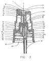
- the closure annular flange 32 of the closure 18 mates with an annular flange 50 of a turret 52 (see Fig. 3 for example) and also supports a gasket or liner 58.
- the gasket or liner 58 is provided with a central aperture and is employed for biasing the annular flange 50 of the turret 52 against the closure annular flange 32 of the closure 18, when the closure 18 is secured to the container 12.
- the closure annular flange 32 of the closure 18 and the gasket or liner 58 sandwich the annular flange 50 of the turret 52 therebetween as the closure 18 is secured to the spout of the container.
- Such sandwiching arrangement is conventional and well known in the art.
- annular side wall 54 of the turret 52 extends through a central aperture, provided in the closure annular flange 32, and the annular side wall 54 extends substantially parallel to the annular skirt 24 of the closure 18 and is spaced therefrom a sufficient distance to allow the annular side wall 36 of the actuator 20 to be readily received therebetween without an undue interference from the side wall 54 during operation of the actuator 20.
- a top free end portion of the turret 52 is provided with an annular retaining edge 56 which first extends radially inwardly and then extends downwardly a short distance, along the longitudinal axis L, toward the base of the closure 18. A further detailed description concerning the purpose of the retaining edge 56 will be provided below.
- An annular lip 59 (see Fig. 2) is provided on an inwardly facing surface of the annular side wall 54 of the turret 52 to facilitate retention of a pump body 60 and a further description concerning the purpose of the same will follow.
- the pump body 60 comprises an outer cylindrical housing 62 which is connected to a base 64 of the pump body 60 to form a single unitary component or structure.
- An inner cylindrical housing 66 is integrally connected to the base 64, of the pump body 60, and the inner cylindrical housing 66 is located concentric with the outer cylindrical housing 62 but spaced therefrom.
- a exterior surface of the pump body 60 supports an annular nub 69 which is located to engage with the annular lip 59 of the turret 52 and secure the pump body 60 to the turret 52.
- a lower portion of the pump body 60 is provided with a cylindrical extension 70 having an inlet aperture 72 formed in a base end surface thereof. A first end of the dip tube 16 is frictionally received and retained within the inlet aperture 72, as is conventionally done in this art.
- the inlet aperture 72 communicates with a first portion of a compression chamber 68, formed between an exterior surface of the inner cylindrical housing 66 and an inwardly facing surface of the outer cylindrical housing 62, via a longitudinal passageway 74.
- the longitudinal passageway 74 extends parallel to but is spaced radially from the longitudinal axis L of the pump assembly.
- a one way valve is located along the longitudinal passageway 74 and the one-way valve comprises a metal ball 76 that is captively retained within a cage 78.
- the cage 78 allows limited to and fro movement of the ball 76 to facilitate opening and closing of the one-way valve.
- This one-way valve allows the product to flow along the longitudinal passageway 74 when the ball 76 is spaced from an annular ball seat 80 (see Fig. 6).
- the ball 76 normally rests, as can be seen in Figs. 3-5, against the annular ball seat 80 to shut off product flow through the longitudinal passageway 74.
- the metal ball 76 Prior to inserting the dip tube 16 within the inlet aperture 72, the metal ball 76 is forced into the inlet aperture 72, and urged past the annular ball seat 80 into the cage 78 where the ball 76 is thereafter permanently retained and utilized to operate the one-way valve.
- the ball 76 is normally held by gravity in a sealing position over the opening defined by the annular ball seat 80 so as to prevent the compressed liquid from being forced back down into the dip tube 16.
- the generated pressure within the compression chamber additional serves to hold the ball 76 in its sealing engagement against the annular ball seat 80.
- a piston 82 is at least partially accommodated within the body 60 and the piston 82 is slidably movable relative to the body 60.
- a first lower end 84 of the piston 82 is provided with an annular sealing lip 86, having an outer circumference slightly larger than the inner dimension of the outer housing 62 to provide a tight sealing engagement between the annular sealing lip 86 and the inner surface of the outer housing 62.
- the pressure generated within the compression chamber 86 assists with forcing the annular sealing lip 86 of the piston 82 into sealing engagement with the inwardly facing surface of the outer cylindrical housing 62.
- An exterior surface of the piston 82, adjacent the annular sealing lip 86, is provided with an annular shoulder 88 which abuts against the annular retaining edge 56 of the turret 52 to captively retain at least the first lower end 84 of the piston 82 within the pump body 60.
- the piston 82 is a generally hollow member which has an exterior side wall that may taper slightly from the first lower end 84 to a second remote end 90.
- a piston outlet 92 is formed adjacent the second remote end 90 of the piston 82.
- the second remote end 90 of the piston 82, located adjacent the piston outlet 92, is provided with a reduced diameter annular cylindrical side wall 94 which is sized to be frictionally received within the central bore 38 of the actuator 20 and provide a secure retaining engagement between the second remote end 90 of the piston 82 and the actuator 20.
- An annular surface of the piston 82, defining the piston outlet 92, forms the poppet valve seat 96.
- the piston outlet 92 is normally closed by a shoulder 106 of an elongate generally cylindrical poppet 98 which is biased against the poppet valve seat 96 via a spring 104.
- the piston outlet 92 is opened and allows the product to be dispensed 14 to flow from the compression chamber 68 to the central bore 38 of the actuator 20, and a further detailed description concerning the same will be provided below.
- a first portion of the compression chamber 68 is formed between the inner cylindrical housing 66 and the outer cylindrical housing 62.
- a remaining second portion of the compression chamber 68 is formed between an inwardly facing surface of the piston 82 and an exterior surface of the poppet 98.
- the hollow interior dimension of the piston 82 is slightly larger than the outer diameter of the inner cylindrical housing 66 and either the piston 82 and/or the inner cylindrical housing 66 may have a channel(s) formed thereon so that the first portion of the compression chamber 68 is in constant communication with the remainder of the compression chamber 68 regardless of the position of the piston 82 relative to the inner cylindrical housing 66.
- the cylindrical poppet 98 is accommodated within a central cavity 100 defined by the inner cylindrical housing 66.
- the poppet 98 is a solid elongate generally cylindrical member which supports an annular sealing and guide surface 102 adjacent a first lower end thereof.
- the annular sealing and guide surface 102 is sized to have an slight interference sliding fit with the inwardly facing surface of the inner cylindrical housing 66.
- the annular sealing and guide surface 102 slides along the inwardly facing surface of the inner cylindrical housing 66, in a sealed manner during operation of the pump assembly, and maintains the poppet 98 aligned with respect to the longitudinal axis L of the pump assembly 10.
- the poppet 98 is biased into a normally closed position, via a spring 104 accommodated within a centrally located interior cavity 100, so that the shoulder 106 of the poppet 98 abuts against the poppet valve seat 96, formed on the piston 82, to shut off flow through the piston outlet 92.
- the poppet 98 has a tapered or smaller constant diameter appendage 108 that extends through the piston outlet 92 and facilitates maintaining proper alignment of the poppet 98 with respect to the outlet 92 during operation of the pump assembly.
- a base of the centrally located interior cavity 100, accommodating the spring 104, is provided with a ventilation port 110 which provides communication between the centrally located interior cavity 100 and an interior space of the container 12 to ventilate the interior cavity so that the centrally located interior 100 is at ambient pressure.
- the ventilation port 110 prevents the creation of either excess pressure or vacuum in the centrally located interior 100 during operation of the pump assembly 10.
- a lower most portion of the poppet 98, opposite the appendage 108, is provided with a cylindrical extension 112 which receives one end of the spring 104 and further facilitates proper alignment and engagement between the poppet 98 and the spring 104.
- a lower inwardly facing surface of the inner cylindrical housing 66 is provided with at least one nub or some other protrusion 114 so that when the annular sealing guiding surface 102 of the poppet 98 engages with the nub or other protrusion 114, the remaining pressure in the compression chamber 68 is relieved and flows downward through the centrally located interior cavity 100 and out through the ventilation port 110, provided in the base 64, into the interior space of the container 12.
- the nub or other protrusion 114 is formed on an inwardly facing surface of the inner cylindrical housing 66 at a location near the end of the stroke of the poppet 98, e.g. after the poppet has moved about 95% to 98% of is normal operating stroke within the inner cylindrical housing 66, so as not to compromise significantly the pumping efficiency of the compression chamber 68.
- protrusion or nub 114 is very useful in "priming" the air normally contained within the compression chamber 68 of the pump assembly following the manufacturing process. Since air is a compressible fluid, the compressed air typically may not generate, even after the full compression stroke of the actuator 20, a sufficient pressure to bias the poppet shoulder 106 away from the poppet valve seat 96 and thereby allow discharge of the compressed air out of the compression chamber 68 into the central bore 38 of the actuator 20.
- the air is immediately released by the breach in the seal formed between the annular sealing and guide surface 102 and the inwardly facing surface of the inner cylindrical housing 66, once the annular sealing and guide surface 102 engages with the nub or the protrusion 114. This released air is conveyed through the central cavity 100 and out the ventilation port 110.
- At least one groove 116 is provided along either an exterior surface of the body 60 or an inwardly facing surface of the turret 52. This groove 116 is normally sealed off from the external environment by the piston shoulder 88 engaging with the annular retaining edge 56 to provide a seal therebetween.
- the exterior surface of the piston 82 is slightly spaced from the annular retaining edge 56 to allow ambient air to flow along the exterior surface of the piston 82 and around the retaining edge 56 and down along the groove 116, located between the exterior surface of the body 60 and the inwardly facing surface of the turret 52, to replace the volume of the product which was just dispensed by the actuator 20.
- This ventilation groove 116 also maintains the pressure inside the container at substantially the same pressure as the external surrounding environment.
- the pump assembly 10 is first installed on a spout of a desired container 12, containing a product to be dispensed 14, by engaging the threads 30 of the closure 18 with a mating thread, or some other conventional retaining mechanism, provided on an exterior surface of the spout of the container 12. Once this has occurred, the dip tube 16 of the pump assembly is submerged within the product to be dispensed 14 such that an inlet of the dip tube is located adjacent a base of the container 12. The pump assembly 10 is now ready for actuation.
- the operator places his or her index finger on the finger recess 34 and depresses the actuator 20, in the direction of arrow A of Fig. 3, so as to bias the actuator 20 downwardly along the longitudinal axis L toward the closure 18.
- Such depression of the actuator 20 in turn, causes a depression of the piston 82 which results in the annular sealing lip 86 sliding along the inwardly facing surface of the outer cylindrical housing 62 in an sealed manner toward the base 64 of the body 60.
- This action causes the product to be dispensed 14, contained within the compression chamber 68, to come under pressure, i.e. it is to be noted that a liquid is generally incompressible.
- this increase in pressure serves to bias the ball 76 against the annular ball seat 80 and thereby prevent the escape of any product downwardly back along the dip tube 16.
- the inwardly facing surface of the piston 82 is spaced a sufficient distance away from the outwardly facing surface of the inner cylindrical housing 66 to allow the product to be dispensed 14 to continuously flow therebetween regardless of the position of the piston 82.
- the generated pressure of the product to be dispensed 14 overcomes the biasing force of the spring 104 and forces the poppet 98 downwardly toward the base 64 of the interior cavity 100 against the action of the spring 104. This movement results in a compression of the spring 104 which allows the poppet shoulder 106 to separate away from the poppet valve seat 96 and thereby establishes a product flow path through the piston outlet 92, as can be seen in Fig. 4.
- the product to be dispensed 14 rushes through the piston outlet 92 and flows upwardly through the central bore 38, the radially bore 40, the inwardly directed channels 48 and is dispensed out through the discharge orifice 44 in a manner which generates a substantially uniform discharge spray configuration from the actuator 20.
- the piston 82 continues to force the product to be dispensed 14 out through the actuator 20, during further downward motion of the actuator in the direction of arrow A, until the annular lip 86 of the piston 82 abuts against the base 64 of the body 60, as seen in Fig. 5.
- an inwardly facing surface of the base 64 of pump body 60 is contoured to closely accommodate and substantially mirror the inwardly facing surface or profile of the annular sealing lip 86 of the piston 82 and thereby minimize the amount of the product to be dispensed 14 still remaining in the compression chamber 68, e.g. the volume of the compression chamber is minimized by this arrangement.
- the volume of the compression chamber 68 has been significantly reduced so that a substantial portion of the product to be dispensed 14, that was previously stored within the compression chamber 68, has been dispensed by the actuation stroke of the actuator 20.
- annular sealing and guide surface 102 engages with the nub or the protrusion 114, formed near a lower portion of the inner cylindrical housing 66, the seal therebetween is breached and most of the remaining product to be dispensed, or air during initial priming of the pump assembly, is conveyed through the interior cavity 100 and out the ventilation port 110 to quickly relieve the generated pressure of the compression chamber 68.
- the finger actuation pressure of the operator is relieved, e.g. the finger of the operator is removed from the finger recess 34.
- the spring 104 immediately biases the poppet 98, in the direction of arrow B of Fig. 6, toward and against the poppet valve seat 96 of the piston 82 to quickly close the piston outlet 92 and thereby prevent the further flow of the product to be dispensed 14 therethrough.
- the spring 104 also biases, due to biasing of the poppet 98 in the direction of arrow B, the piston 82 and the actuator 20 in an upward direction away from the closure 18.
- the cage 78 captively retains the ball 76, e.g. opens this one-way valve but retains the ball 76 so that the ball 76 may fall, due to the effects of gravity, back on the ball valve seat 80 following completion of the pump assembly return stroke to close this one-way valve.
- the product to be dispensed 14 continues to flow along longitudinal passageway 74 into the compression chamber 68 where the product to be dispensed 14 is accumulated and stored, as can be seen in Fig. 3.
- a second embodiment of the present invention will now be discussed. As this second embodiment is very similar to the first embodiment in many aspects, only the differences between the second and the first embodiments will be discussed in detail.
- the closure 18, the actuator 20, the ball 76, the piston 82, the poppet 98 and the spring 104 are identical in both embodiments and thus a further detail discussion concerning the same in not generally provided.
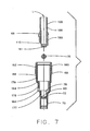
- a first difference is that the pump body 60 is formed as two separate components, i.e. the first component comprises the outer cylindrical housing 162 integral formed with the base 164 of the pump body 160 to form a unitary component or structure while the inner cylindrical housing 166 is a completely separate component.
- the interior of the pump body 160 has three distinct sections each having a different diameter, i.e. a first smaller diameter section 177 located adjacent a base of the pump body 160, a third larger diameter section 179 located adjacent an open end of the pump body 160, and a second intermediate diameter section 178 located between the smaller diameter section 177 and the larger diameter section 179.
- a lower cylindrical portion 180 of the inner cylindrical housing 166 is sized to have an interference fit, e.g. a few thousands of an inch or so, with the second intermediate section 178 of the pump body 160 so that the inner cylindrical housing 166 can be located concentric with respect to the outer cylindrical housing 162 and be captively retained thereby once engaged with the pump body 160.
- a second difference is that a lower side wall section of the pump body 160 is provided with an aperture 184 and this aperture 184 is located to coincide with the ventilation port 110 formed in a side wall of the inner cylindrical housing 166, once the inner cylindrical housing 166 is received within the internal diameter of the base 164 of the pump body 160.
- the ventilation port 110 provides communication between the centrally located interior cavity 100 and an interior space of the container 12 to ventilate the interior cavity so that the centrally located interior 100 is at ambient pressure and prevents the creation of either excess pressure or vacuum in the centrally located interior 100 during operation of the pump assembly 10.
- a third difference relates to the retention of the metal ball 76.
- the metal ball 76 is first placed within the pump body 160 and received by the first smaller diameter bore 177, prior to placing the inner cylindrical housing 166 within the internal diameter of the base 164 of the pump body 160. Thereafter, once the inner cylindrical housing 166 is received within the internal diameter of the base 164 of the pump body 160, a base 181 of inner cylindrical housing 166 functions as a stop to prevent the metal ball 76 from being dislodged from the first smaller diameter bore 177 thereby eliminating the need for the cage 78, as with the previous embodiment.
- a fourth difference relates to the arrangement of the centrally located interior cavity 100 with respect to the inlet aperture 72 and the first smaller diameter bore 177.
- the centrally located interior cavity 100 has a longitudinal axis which coincides with the longitudinal axis L of the pump assembly while the inlet aperture 72 and the bore accommodating the metal ball 76 each have a longitudinal axis which extends parallel to by is offset with respect to the longitudinal axis L of the pump assembly.
- the centrally located interior cavity 100 as well as both the inlet aperture 72 and the first smaller diameter bore 177 are all have longitudinal axes which coincide with the longitudinal axis L of the pump assembly.
- An exterior surface of the pump body 160 supports an annular nub 69 which is located to engage with the annular lip 59 of the turret 52 and secure the pump body 160 to the turret 52.
- a lower portion of the pump body 160 is provided with a cylindrical extension 70 having an inlet aperture 72 formed in a base end surface thereof. A first end of the dip tube 16 is frictionally received and retained within the inlet aperture 72, as is conventionally done in this art.
- the inlet aperture 72 communicates with a first portion of a compression chamber 68, formed between an exterior surface of the inner cylindrical housing 166 and an inwardly facing surface of the outer cylindrical housing 162, via a longitudinal passageway 74.
- the longitudinal passageway 74 extends parallel to but is spaced radially from the longitudinal axis L of the pump assembly.
- the metal ball 76 moves to and fro within the first smaller diameter section of the pump body 160 and forms a one way valve. This one-way valve allows the product to flow along the longitudinal passageway 74 when the ball 76 is spaced from an annular ball seat 80. As with the pervious embodiment, the ball 76 normally rests against the annular ball seat 80 to shut off product flow through the longitudinal passageway 74.
- a piston 82 is at least partially accommodated within the pump body 160 and the piston 82 is slidably movable relative to the pump body 160.
- a first lower end 84 of the piston 82 is provided with an annular sealing lip 86, having an outer circumference slightly larger than the inner dimension of the outer housing 62 to provide a tight sealing engagement between the annular sealing lip 86 and the inner surface of the outer housing 162.
- the pressure generated within the compression chamber 86 assists with forcing the annular sealing lip 86 of the piston 82 into sealing engagement with the inwardly facing surface of the outer cylindrical housing 162.
- An exterior surface of the piston 82, adjacent the annular sealing lip 86, is provided with an annular shoulder 88 which abuts against the annular retaining edge 56 of the turret 52 to captively retain at least the first lower end 84 of the piston 82 within the pump body 160.
- a first portion of the compression chamber 68 is formed between the inner cylindrical housing 166 and the outer cylindrical housing 162.
- a remaining second portion of the compression chamber 68 is formed between an inwardly facing surface of the piston 82 and an exterior surface of the poppet 98.
- the hollow interior dimension of the piston 82 is slightly larger than the outer diameter of the inner cylindrical housing 166 and either the piston 82 and/or the inner cylindrical housing 166 may have a channel(s) formed thereon so that the first portion of the compression chamber 68 is in constant communication with the remainder of the compression chamber 68 regardless of the position of the piston 82 relative to the inner cylindrical housing 166.
- the cylindrical poppet 98 is accommodated within a centrally located internal cavity 100 defined by the inner cylindrical housing 166.
- the poppet 98 is a solid elongate generally cylindrical member which supports an annular sealing and guide surface 102 adjacent a first lower end thereof.
- the annular sealing and guide surface 102 is sized to have a slight interference sliding fit with the inwardly facing surface of the inner cylindrical housing 166.
- the annular sealing and guide surface 102 slides along the inwardly facing surface of the inner cylindrical housing 166, in a sealed manner during operation of the pump assembly, and maintains the poppet 98 aligned with respect to the longitudinal axis L of the pump assembly 10.
- the poppet 98 is biased into a normally closed position, via a spring 104 accommodated within the centrally located interior cavity 100, so that the shoulder 106 of the poppet 98 abuts against the poppet valve seat 96, formed on the piston 82, to shut off flow through the piston outlet 92.
- a lower inwardly facing surface of the inner cylindrical housing 166 is provided with at least one nub or some other protrusion 114 so that when the annular sealing guiding surface 102 of the poppet 98 engages with the nub or some other protrusion, the remaining pressure in the compression chamber 68 is relieved and flows downward through the centrally located interior cavity 100 and out through the ventilation port 110 and aperture 184, provided in the base 164, into the interior space of the container 12.
- the compression chamber which has a maximum transverse dimension or diameter of between 5.7 and 7.0 mm (0.225 and 0.275 inches), and more preferably a diameter of about 6.4 mm (0.250 inches) and the piston has a stroke length of between 7.0 mm and 8.3 mm (0.275 and about 0.325 inches), and more preferably a piston stroke length of about 7.6 mm (0.300 inches).
- a compression chamber diameter to piston stroke ratio of between about 4 to 5 and about 2 to 3 which facilitates achievement of an operating pressure of approximately 0.9 MPa (130 psi), or so.
- the spring 104 will immediately bias the poppet 98 in the direction of arrow B of the Fig. 6, toward and against the poppet valve seat 96. This biasing action quickly closes the piston outlet 92 and thereby prevents the further flow of product to be dispensed 14 therethrough.
- passageway 74 leading to the compression chamber 68 extends along a second longitudinal axis LP which is off set with respect to the longitudinal axis L of the pump assembly but extends substantially parallel thereto.
- This arrangement facilitates venting of the base 64 of the central cavity 100 to the interior space of the container 12 so that the central cavity 100 operates at ambient pressure or to some other pressure other than the operating pressure of the compression chamber.
Abstract
Description
- The invention relates to an improved manually operated pump assembly, categorized as an accumulative pump, for dispensing a product under high pressure. The pump assembly comprises a compression chamber for pressurization of the product to be dispensed and a relief valve operating, substantially at ambient atmosphere, for controlling the release of product through a piston outlet of the pump.
- A variety of prior art manually operated hand-held pump assemblies are well known and used for dispensing a variety of products such as liquids for personal care and pharmaceutical uses, fragrance products and the like. Pumps of this type comprise a housing body and a slidable piston which together define a compression chamber for receiving and dispensing of the product. The body, as well as the internal components contained within the body, are retained by a turret. An inlet in the base of the body communicates, via a dip tube, with the product to be dispensed. A conventional spray actuator communicates with an outlet of the piston to facilitate operation of the pump and provides a mechanical mechanism for dispensing the product, as desired, by an operator.
- Directional flow of product to be dispensed, from the interoir of the container into the compression chamber of the body, is controlled by a first one-way valve, typically located at or adjacent to the coupling of the body inlet to the dip tube. A second one-way valve enables the product to be dispensed from the compression chamber through the piston outlet and into a supply passage of the actuator. Finally, the product is dispensed out through a discharge orifice of the actuator.
- It is desirable for the pump to reach a specified pressure, prior to releasing the product to be dispensed from the compression chamber, to ensure that the product dispensed out the discharge orifice exhibits consistent and uniform spray characteristics. For example, some sprays need to consist of particles of uniform size, e.g. particles lying within a narrow particle size range, in order for proper dispensing of the product. It is also desirable to dispense a specific-dosage of product during a single actuation of the actuator. To accomplish both the desired dosage and particle size requirements, the construction and function of the pump assembly require accurately designed internal components which must be precisely controlled during operation of the pump assembly. Because the body, the piston, the spring, the valve, etc., determine the configuration and operating pressure of the compression chamber, these components are very important in controlling the function of the pump assembly.
- Product dispensing requirements are increasingly more demanding. With an increase in the use of low volatile solvents, as the main carrier component for the product to be dispensed, and as well as using more viscous gel-type liquids, the design requirements for dispensing such products are more critical. In particular, the low volatile solvents and the viscous gel-type liquids require higher discharge pressures, to facilitate proper dispensing thereof, versus products that include solvents which are readily converted into vapor upon discharge. In an attempt to overcome this problem and facilitate control of the resulting spray configuration, many prior art pump assemblies use a single spring to both actuate the piston and also bias a second one-way valve. This single spring forces the piston back into its initial static position, once the actuator has actuated the piston, and holds the second one-way valve closed until a desired operating pressure is reached.
- Other prior art designs use a first spring for returning the piston and a second spring for biasing the second one-way valve independently of the piston. The intended advantage of the two spring arrangement is that the second one-way valve spring can be independently adjusted to facilitate opening of the piston valve at a desired operating pressure. In either case, the second one-way valve and the spring(s) are all contained within the compression chamber of the body and are subjected to the generated operating pressure within the compression chamber. The spring(s) (or other known conventional biasing members) are typically located to bias the second one-way valve against a piston valve seat. The amount of pressure required to compress the spring, and thus move the second one-way valve away from its associated valve seat, determines the operating pressure of the pump assembly. The construction of the spring thus determines the pressure at which the product is displaced from the body out through the discharge orifice. The spring pressure translates into a high reaction force upon the product as it is released by the second one-way valve and overcomes the spring bias.
- It is to be appreciated that in order for the pump assembly to dispense liquid properly, the pump section of the assembly must be initially purged of any air contained within the compression chamber-this initial purging step is commonly referred to as "priming" of the pump. When the actuator is initially depressed by an operator, any air contained within the compression chamber of the body must be displaced in order for product to be siphoned into the compression chamber of the body via the dip tube. By depressing the actuator, the piston is moved toward a base of the body thereby compressing the spring as well as any air contained within the compression chamber. The compressed air assists with maintaining the first one-way valve in a closed position. The compressed air also induces an opening force on the second one-way valve but, in most cases, the induced force of the compressed air may never reach a high enough pressure to overcome the spring closing force of the second one-way valve. For this reason, prior art pumps use a small rib(s), or some other mechanical device located near the end of the compression stroke, to disrupt the seal between an inner part of the body and the piston and allow the compressed air to escape from the compression chamber. Two methods are used for allowing the compressed air to escape from the compression chamber. The first method is to allow the air to escape around the piston which can result in residual product drying along the escape path and seizing the piston. The second method is to allow air to escape down the dip tube which results in the air and the product to be dispensed reciprocating back and forth within the tube, which is also undesirable.
- Because both the second one-way valve and the spring occupy space inside the body, these components effect the compression of the air during the priming operation of the pump, and thus effect the operation of the second one-way valve. This also means that the product, siphoned via the dip tube into the body, is then pushed back through the system in the reverse direction as the piston reciprocates. This to and fro movement of the air and the product reduces the efficiency of the pump and increases the force needed to operate the system. In addition, the number of strokes required in order to remove the air contained within the compression chamber is increased.
- U.S. Patent No. 5,626,264 relates to a pump sprayer, according to the preamble of
Claim 1, with a priming ramp for deflecting the lower end of a poppet valve member, at the end of the plunger stroke, for cocking the valve member so as to disrupt its sealing action with the discharge valve seat and permit air to be released from the pump chamber through the discharge orifice to the atmosphere. - Wherefore, it is an object of the present invention to overcome the aforementioned problems and drawbacks associated with the prior art pump assembly designs.
- Another object of the present invention to design a pump assembly, utilizing a smaller number of components, which is efficiently primed and operated while still ensuring a high dispensing efficiency for the pump assembly.
- A further object of the invention is to provide a movable poppet which operates at ambient pressure so that the function of the poppet is essentially unaffected by the flow or circulation of the product to be dispensed within the compression chamber.
- Still another object of the invention is to increase the compression efficiency of the pump assembly and also minimize the number of strokes required to "prime" the pump assembly by providing a spring which is not located along or in communication with the product dispensing flow path so that the spring is not hindered by and does not hinder or interfere with the flow of the product to be dispensed.
- Yet another object of the invention is to provide a simpler, lower cost, higher quality and efficient spray pump assembly that provides the same spray characteristics for low volatile solvents, water based products, alcohol base and/or other formulas.
- A still further object of the invention is provide a pump assembly having a dispensing dosage of between about 120-250 ml of product, or so, an actuation force of between about 24.47-33.36 N (5.5-7.5 lbs)., or so, and an internal operating pressure of the compression chamber of between about 0.69-1.17 MPa (100 to 170 psi), or so.
- The manually actuated pump assembly, according to the present invention, is capable of dispensing a wide range of products. The highly efficient internal volume and priming system, according to the present invention, renders the manually actuated pump assembly ideal for use with personal care products, pharmaceuticals, fragrances, etc. A majority of the structural components of the manually actuated pump, according to the present invention, are located outside of the compression chamber thereby allowing minimal clearance between the inwardly facing surfaces defining the compression chamber when those surfaces are moved into the fully actuated position. Such design of the pump assembly aids in both priming and normal operation of the pump assembly.
- Priming is accomplished by venting the trapped air either out through the discharge orifice or past a seal formed between the poppet and an inner cylindrical housing, rather than down the dip tube or around the compression piston. The prior art dispensing systems, that prime through the dip tube, experience difficulties when dispensing gels or high water content products or when utilizing a long length dip tube. As note above, the pump assemblies that prime around the compression piston have a tendency to become clogged or seized due to drying of the product residue.
- During normal operation, according to the present invention, the pump assembly has a high operating pressure due to the ratio of the compression chamber diameter to the piston stroke length. With an operation pressure of approximately 130 psi or so, the manually actuated pump according to the present invention operates about 30% higherthan conventional pumps currently available on the market today. Another advantage of the high compression design, of the present invention, is the uniform spray consistently achieved during each dispensing stroke. In addition, less variation in the internal volume results by locating the spring and valving components external of the compression chamber. Lastly, the improved profile of the components provides substantially unrestricted flow of the product from the compression chamber to the discharge orifice.
- Finally, the present invention relates to a finger pump apparatus according to
claim 1. -
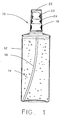
- Fig. 1 is a diagrammatic front perspective view of a container supporting the improved pump assembly according to the present invention;
- Fig. 2 is a diagrammatic cross-sectional view of a first embodiment of the improved pump assembly, according to the present invention, shown in a static position without an overcap, an actuator, a closure, a liner, or a dip tube affixed thereto;
- Fig. 3 is a diagrammatic cross-sectional view of the first embodiment of the improved pump assembly, according to the present invention, shown in the static position with an actuator, a closure, a liner and a dip tube attached thereto;
- Fig. 4 is a diagrammatic cross-sectional view, of the first embodiment of the improved pump assembly of Fig. 3, shown in a partially depressed position in which the poppet has been sufficiently displaced from the poppet annular seat to commence dispensing of product;
- Fig. 5 is a diagrammatic cross-sectional view of the first embodiment of the improved pump assembly of Fig. 3 showing the fully depressed position of the pump assembly;
- Fig. 6 is a diagrammatic cross-sectional view, of the first embodiment of the improved pump assembly of Fig. 3, shown in its partially returned position in which the poppet is biased against the poppet annular seat to facilitate suction of the product into the compression chamber during the return stroke of the improved pump assembly;
- Fig. 7 is a diagrammatic cross-sectional exploded view of a second embodiment of the pump body for the improved pump assembly, according to the present invention; and
- Fig. 8 is a diagrammatic cross-sectional view of the second embodiment of the improved pump assembly, according to the present invention, shown in the static position with an actuator, a closure, a liner and a dip tube attached thereto.
-
- While this invention is susceptible to various embodiments, the specification and the accompanying drawings disclose two specific forms as examples of the present invention. For ease of description, the pump assembly embodying this invention is described in the normal operating position, in terms such as: upper, lower, horizontal, etc., are used with reference to this position. It will be understood, however, that the pumps and components embodying this invention may be manufactured, stored, transported, used, and sold in an orientation other than the position described.
- Turning first to Fig. 1, a brief description concerning the
improved pump assembly 10, according to the present invention, used in combination with aprior art container 12 will now be provided. As can be seen in this Figure, thecontainer 12 is a generally closed plastic container which has a spout (not shown in detail) formed on the top surface of the container. The spout is provided with an external thread (not shown) and has an aperture or opening formed therein to provide communication with an interior of thecontainer 12. Thecontainer 12 accommodates a desired quantity of liquid, fluid or some other product to be dispensed 14. The product to be dispensed 14 is typically supplied from an interior space or area of thecontainer 12, via adip tube 16, to an inlet of thepump assembly 10. As is well known in the art, the bottom end of thedip tube 16 is normally submerged in the liquid or product when the container is in a generally in an upright orientation, as illustrated in Fig. 1. A further detailed description concerning the function of thedip tube 16 will be provided below. - The
pump assembly 10 is provided with removable cap orclosure 18 which accommodates adepressible actuator 20 that is movable relative to theclosure 18 to facilitate actuation of thepump assembly 10, and a further detailed description concerning the purpose of such depression will follow below. If desired, a removable hood orovercap 22, can encase or enclose theactuator 20 to prevent inadvertent actuation thereof. Theovercap 22 is hollow shell member and typically has a perimeter edge that has a friction fit with a hollowannular skirt 24 extending from a top surface of theclosure 18. As such overcap feature in conventional and well known in the art, a further detailed description concerning the same is not provided. - With reference now to Figs. 2-6, a detailed description concerning a first embodiment of the
improved pump assembly 10, according to the present invention, will now be provided. As can be seen in Figs. 3-6, for example, the base portion of theclosure 18 is provided with anannular base flange 26 which is located to abut against a mating flange surface (not shown in detail) of thecontainer 12. In addition, theclosure 18 is provided with a central throughbore 28 extending through theclosure 18 along a longitudinal axis L of theimproved pump assembly 10. An inwardly facingsurface 29 of the base of theclosure 18 is provided with an internal thread 30 (or some other conventional retaining recess, lip or mechanism) for engagement with a mating external thread (or some other mating conventional retaining recess, lip or mechanism) provided on the spout of thecontainer 12. Theclosure 18 is also provided with a substantially centrally located, radially inwardly extending horizontal closureannular flange 32 which separates a base portion of theclosure 18 from theannular skirt 24. The closureannular flange 32 facilitates retention of the various components of theimproved pump assembly 10 as will be discussed below in further detail. - A top surface of the
actuator 20 is provided with afinger recess 34 which is preferably shaped or contoured to facilitate engagement with an index finger of an operator. As such shaping or contouring feature is well known in the art, a further description concerning the same is not provided. Theactuator 20 is further provided with a downwardly extendingannular side wall 36 which has a diameter that is slightly less than an inside diameter of theannular skirt 24 of theclosure 18 to allow theannular side wall 36 of theactuator 20 to move relative to theannular skirt 24, e.g. to move in and out of the space encompassed by theannular skirt 24 of theclosure 18 without excess friction or contact occurring between those two components. According to a preferred embodiment of the invention, there is a relative sliding motion between an outwardly facing surface of theannular side wall 36 and an inwardly facing surface of theannular skirt 24 to facilitate guiding theactuator 20 as it is actuated or depressed toward theclosure 18. Such sliding motion facilitates maintaining theactuator 20 in its correct upright dispensing orientation. - An internal longitudinal
central bore 38 is formed within the interior of theactuator 20 and thecentral bore 38, in turn, communicates with a transverse radial bore 40. The transverse radial bore 40 terminates at an opening formed in an exterior surface of the actuator which is sealed or closed byinsert member 42. Theinsert member 42 has a dischargedorifice 44 formed therein. The dischargedorifice 44 facilitates dispensing of the product to the dispensed 14 out of the actuator into the external environment. Theinsert member 42 is received within the transverse radial bore 40 and an outer periphery of theinsert member 42 has a friction fit with an inner wall defining the transverse radial bore 40 to permanently retain theinsert member 42 therein. An inwardly facing surface, located on the base of theinsert member 42, engages with an outwardly facing planar end surface of acentral post 46 accommodated within the radial bore 40. The end surface of thepost 46 has a plurality of conventional radially inwardly directedchannels 48 which lead to a conventional mixing chamber (not separately numbered) centrally formed on the end surface of thepost 46. It will be apparent to one skilled in the art that the plurality of radially inwardly directedchannels 48 and the mixing chamber may also be located on and supported by the inwardly facing base surface of theinsert member 42, instead of thepost 46, for engagement with a substantially flat end surface of thepost 46. The mixing chamber directly communicates with thedischarge orifice 44 for dispensing the throughly mixed and/or swirled product to be dispensed 14 out through thedischarge orifice 44. As this dispensing arrangement is conventional and well known in the art, a further detailed description concerning the same is not provided. - The closure
annular flange 32 of theclosure 18 mates with anannular flange 50 of a turret 52 (see Fig. 3 for example) and also supports a gasket orliner 58. The gasket orliner 58 is provided with a central aperture and is employed for biasing theannular flange 50 of theturret 52 against the closureannular flange 32 of theclosure 18, when theclosure 18 is secured to thecontainer 12. The closureannular flange 32 of theclosure 18 and the gasket orliner 58 sandwich theannular flange 50 of theturret 52 therebetween as theclosure 18 is secured to the spout of the container. Such sandwiching arrangement is conventional and well known in the art. - An
annular side wall 54 of theturret 52 extends through a central aperture, provided in the closureannular flange 32, and theannular side wall 54 extends substantially parallel to theannular skirt 24 of theclosure 18 and is spaced therefrom a sufficient distance to allow theannular side wall 36 of theactuator 20 to be readily received therebetween without an undue interference from theside wall 54 during operation of theactuator 20. A top free end portion of theturret 52 is provided with anannular retaining edge 56 which first extends radially inwardly and then extends downwardly a short distance, along the longitudinal axis L, toward the base of theclosure 18. A further detailed description concerning the purpose of the retainingedge 56 will be provided below. An annular lip 59 (see Fig. 2) is provided on an inwardly facing surface of theannular side wall 54 of theturret 52 to facilitate retention of apump body 60 and a further description concerning the purpose of the same will follow. - The
pump body 60, as can be seen in further detail with reference to Fig. 2, comprises an outercylindrical housing 62 which is connected to abase 64 of thepump body 60 to form a single unitary component or structure. An innercylindrical housing 66 is integrally connected to thebase 64, of thepump body 60, and the innercylindrical housing 66 is located concentric with the outercylindrical housing 62 but spaced therefrom. A exterior surface of thepump body 60 supports anannular nub 69 which is located to engage with theannular lip 59 of theturret 52 and secure thepump body 60 to theturret 52. A lower portion of thepump body 60 is provided with acylindrical extension 70 having aninlet aperture 72 formed in a base end surface thereof. A first end of thedip tube 16 is frictionally received and retained within theinlet aperture 72, as is conventionally done in this art. - The
inlet aperture 72 communicates with a first portion of acompression chamber 68, formed between an exterior surface of the innercylindrical housing 66 and an inwardly facing surface of the outercylindrical housing 62, via alongitudinal passageway 74. Thelongitudinal passageway 74 extends parallel to but is spaced radially from the longitudinal axis L of the pump assembly. A one way valve is located along thelongitudinal passageway 74 and the one-way valve comprises ametal ball 76 that is captively retained within acage 78. Thecage 78 allows limited to and fro movement of theball 76 to facilitate opening and closing of the one-way valve. This one-way valve allows the product to flow along thelongitudinal passageway 74 when theball 76 is spaced from an annular ball seat 80 (see Fig. 6). Theball 76 normally rests, as can be seen in Figs. 3-5, against theannular ball seat 80 to shut off product flow through thelongitudinal passageway 74. Prior to inserting thedip tube 16 within theinlet aperture 72, themetal ball 76 is forced into theinlet aperture 72, and urged past theannular ball seat 80 into thecage 78 where theball 76 is thereafter permanently retained and utilized to operate the one-way valve. - It is to be appreciated that the
ball 76 is normally held by gravity in a sealing position over the opening defined by theannular ball seat 80 so as to prevent the compressed liquid from being forced back down into thedip tube 16. During actuation of the actuator, i.e. either during priming of the pump or dispensing of product, the generated pressure within the compression chamber additional serves to hold theball 76 in its sealing engagement against theannular ball seat 80. A further detailed description concerning the purposed of the same will follow below. - A
piston 82 is at least partially accommodated within thebody 60 and thepiston 82 is slidably movable relative to thebody 60. A firstlower end 84 of thepiston 82 is provided with anannular sealing lip 86, having an outer circumference slightly larger than the inner dimension of theouter housing 62 to provide a tight sealing engagement between theannular sealing lip 86 and the inner surface of theouter housing 62. During operation of thepiston 82, as will be described below in further detail, the pressure generated within thecompression chamber 86 assists with forcing theannular sealing lip 86 of thepiston 82 into sealing engagement with the inwardly facing surface of the outercylindrical housing 62. An exterior surface of thepiston 82, adjacent theannular sealing lip 86, is provided with anannular shoulder 88 which abuts against theannular retaining edge 56 of theturret 52 to captively retain at least the firstlower end 84 of thepiston 82 within thepump body 60. - The
piston 82 is a generally hollow member which has an exterior side wall that may taper slightly from the firstlower end 84 to a secondremote end 90. Apiston outlet 92 is formed adjacent the secondremote end 90 of thepiston 82. The secondremote end 90 of thepiston 82, located adjacent thepiston outlet 92, is provided with a reduced diameter annularcylindrical side wall 94 which is sized to be frictionally received within thecentral bore 38 of theactuator 20 and provide a secure retaining engagement between the secondremote end 90 of thepiston 82 and theactuator 20. An annular surface of thepiston 82, defining thepiston outlet 92, forms thepoppet valve seat 96. Thepiston outlet 92 is normally closed by ashoulder 106 of an elongate generallycylindrical poppet 98 which is biased against thepoppet valve seat 96 via aspring 104. When thecylindrical poppet 98 becomes spaced from thepoppet valve seat 96, during actuation of the pump assembly, thepiston outlet 92 is opened and allows the product to be dispensed 14 to flow from thecompression chamber 68 to thecentral bore 38 of theactuator 20, and a further detailed description concerning the same will be provided below. - As stated above, a first portion of the
compression chamber 68 is formed between the innercylindrical housing 66 and the outercylindrical housing 62. A remaining second portion of thecompression chamber 68 is formed between an inwardly facing surface of thepiston 82 and an exterior surface of thepoppet 98. The hollow interior dimension of thepiston 82 is slightly larger than the outer diameter of the innercylindrical housing 66 and either thepiston 82 and/or the innercylindrical housing 66 may have a channel(s) formed thereon so that the first portion of thecompression chamber 68 is in constant communication with the remainder of thecompression chamber 68 regardless of the position of thepiston 82 relative to the innercylindrical housing 66. - The
cylindrical poppet 98 is accommodated within acentral cavity 100 defined by the innercylindrical housing 66. Thepoppet 98 is a solid elongate generally cylindrical member which supports an annular sealing and guidesurface 102 adjacent a first lower end thereof. The annular sealing and guidesurface 102 is sized to have an slight interference sliding fit with the inwardly facing surface of the innercylindrical housing 66. The annular sealing and guidesurface 102 slides along the inwardly facing surface of the innercylindrical housing 66, in a sealed manner during operation of the pump assembly, and maintains thepoppet 98 aligned with respect to the longitudinal axis L of thepump assembly 10. Thepoppet 98 is biased into a normally closed position, via aspring 104 accommodated within a centrally locatedinterior cavity 100, so that theshoulder 106 of thepoppet 98 abuts against thepoppet valve seat 96, formed on thepiston 82, to shut off flow through thepiston outlet 92. As can be seen in Fig. 2, for example, thepoppet 98 has a tapered or smallerconstant diameter appendage 108 that extends through thepiston outlet 92 and facilitates maintaining proper alignment of thepoppet 98 with respect to theoutlet 92 during operation of the pump assembly. - A base of the centrally located
interior cavity 100, accommodating thespring 104, is provided with aventilation port 110 which provides communication between the centrally locatedinterior cavity 100 and an interior space of thecontainer 12 to ventilate the interior cavity so that the centrally located interior 100 is at ambient pressure. Theventilation port 110 prevents the creation of either excess pressure or vacuum in the centrally located interior 100 during operation of thepump assembly 10. A lower most portion of thepoppet 98, opposite theappendage 108, is provided with acylindrical extension 112 which receives one end of thespring 104 and further facilitates proper alignment and engagement between thepoppet 98 and thespring 104. - In a preferred form of the invention, a lower inwardly facing surface of the inner
cylindrical housing 66 is provided with at least one nub or someother protrusion 114 so that when the annularsealing guiding surface 102 of thepoppet 98 engages with the nub orother protrusion 114, the remaining pressure in thecompression chamber 68 is relieved and flows downward through the centrally locatedinterior cavity 100 and out through theventilation port 110, provided in thebase 64, into the interior space of thecontainer 12. It is to be appreciated that the nub orother protrusion 114 is formed on an inwardly facing surface of the innercylindrical housing 66 at a location near the end of the stroke of thepoppet 98, e.g. after the poppet has moved about 95% to 98% of is normal operating stroke within the innercylindrical housing 66, so as not to compromise significantly the pumping efficiency of thecompression chamber 68. - The use of the protrusion or
nub 114 is very useful in "priming" the air normally contained within thecompression chamber 68 of the pump assembly following the manufacturing process. Since air is a compressible fluid, the compressed air typically may not generate, even after the full compression stroke of theactuator 20, a sufficient pressure to bias thepoppet shoulder 106 away from thepoppet valve seat 96 and thereby allow discharge of the compressed air out of thecompression chamber 68 into thecentral bore 38 of theactuator 20. According to the present invention, if theactuator 20 is substantially completely depressed and thepoppet shoulder 106 still has not been biased away from thepoppet valve seat 96 to thereby open thepiston outlet 92, the air is immediately released by the breach in the seal formed between the annular sealing and guidesurface 102 and the inwardly facing surface of the innercylindrical housing 66, once the annular sealing and guidesurface 102 engages with the nub or theprotrusion 114. This released air is conveyed through thecentral cavity 100 and out theventilation port 110. On the return stroke of theactuator 20, however, as soon as the annular sealing and guidesurface 102 clears the nub or theprotrusion 114 and again establishes a seal with the innercylindrical housing 66, a siphoning action is created within thecompression chamber 68 and a quantity of the product to be dispensed 14 is siphoned, via thedip tube 16 andpassageway 74, toward thecompression chamber 68. This siphoned product will eventually flow into thecompression chamber 68 where the product, which is generally an incompressible fluid, will actuate thepoppet 98 in its intended dispensing manner after a sufficient number, e.g. four (4), of priming strokes. - It is to be appreciated that if replacement air is not allowed to enter inside the
container 12 and replace the volume of dispensedproduct 14, during normal operation of the pump, thecontainer 12 will progressively become evacuated and eventually deform inwardly and/or collapse once a substantial portion of the product to be dispensed is sprayed. To alleviate this problem, at least onegroove 116 is provided along either an exterior surface of thebody 60 or an inwardly facing surface of theturret 52. Thisgroove 116 is normally sealed off from the external environment by thepiston shoulder 88 engaging with theannular retaining edge 56 to provide a seal therebetween. Once thepiston 82 is sufficiently depressed, the exterior surface of thepiston 82 is slightly spaced from theannular retaining edge 56 to allow ambient air to flow along the exterior surface of thepiston 82 and around the retainingedge 56 and down along thegroove 116, located between the exterior surface of thebody 60 and the inwardly facing surface of theturret 52, to replace the volume of the product which was just dispensed by theactuator 20. Thisventilation groove 116 also maintains the pressure inside the container at substantially the same pressure as the external surrounding environment. - Now that a detailed description concerning the basic components of the pump assembly, according to the present invention, were provided, a detailed description concerning actuation of the pump assembly will now be described.
- Initially the
pump assembly 10 is first installed on a spout of a desiredcontainer 12, containing a product to be dispensed 14, by engaging thethreads 30 of theclosure 18 with a mating thread, or some other conventional retaining mechanism, provided on an exterior surface of the spout of thecontainer 12. Once this has occurred, thedip tube 16 of the pump assembly is submerged within the product to be dispensed 14 such that an inlet of the dip tube is located adjacent a base of thecontainer 12. Thepump assembly 10 is now ready for actuation. - When actuation is desired, the operator places his or her index finger on the
finger recess 34 and depresses theactuator 20, in the direction of arrow A of Fig. 3, so as to bias theactuator 20 downwardly along the longitudinal axis L toward theclosure 18. Such depression of theactuator 20, in turn, causes a depression of thepiston 82 which results in theannular sealing lip 86 sliding along the inwardly facing surface of the outercylindrical housing 62 in an sealed manner toward thebase 64 of thebody 60. This action causes the product to be dispensed 14, contained within thecompression chamber 68, to come under pressure, i.e. it is to be noted that a liquid is generally incompressible. As the pressure of the product to be dispensed increases, this increase in pressure serves to bias theball 76 against theannular ball seat 80 and thereby prevent the escape of any product downwardly back along thedip tube 16. As noted above, the inwardly facing surface of thepiston 82 is spaced a sufficient distance away from the outwardly facing surface of the innercylindrical housing 66 to allow the product to be dispensed 14 to continuously flow therebetween regardless of the position of thepiston 82. Once the pressure within thecompression chamber 68 increases to a sufficient pressure, e.g. an operating pressure of about 130 psi, the generated pressure of the product to be dispensed 14 overcomes the biasing force of thespring 104 and forces thepoppet 98 downwardly toward thebase 64 of theinterior cavity 100 against the action of thespring 104. This movement results in a compression of thespring 104 which allows thepoppet shoulder 106 to separate away from thepoppet valve seat 96 and thereby establishes a product flow path through thepiston outlet 92, as can be seen in Fig. 4. - Once the
poppet shoulder 106 is sufficiently spaced from thepoppet valve seat 96, the product to be dispensed 14 rushes through thepiston outlet 92 and flows upwardly through thecentral bore 38, the radially bore 40, the inwardly directedchannels 48 and is dispensed out through thedischarge orifice 44 in a manner which generates a substantially uniform discharge spray configuration from theactuator 20. Thepiston 82 continues to force the product to be dispensed 14 out through theactuator 20, during further downward motion of the actuator in the direction of arrow A, until theannular lip 86 of thepiston 82 abuts against thebase 64 of thebody 60, as seen in Fig. 5. Once the pump assembly is in its fully depressed position, an inwardly facing surface of thebase 64 ofpump body 60 is contoured to closely accommodate and substantially mirror the inwardly facing surface or profile of theannular sealing lip 86 of thepiston 82 and thereby minimize the amount of the product to be dispensed 14 still remaining in thecompression chamber 68, e.g. the volume of the compression chamber is minimized by this arrangement. As is apparent from Fig. 5, the volume of thecompression chamber 68 has been significantly reduced so that a substantial portion of the product to be dispensed 14, that was previously stored within thecompression chamber 68, has been dispensed by the actuation stroke of theactuator 20. - It is to be appreciated when the annular sealing and guide
surface 102, seen in Fig. 5, engages with the nub or theprotrusion 114, formed near a lower portion of the innercylindrical housing 66, the seal therebetween is breached and most of the remaining product to be dispensed, or air during initial priming of the pump assembly, is conveyed through theinterior cavity 100 and out theventilation port 110 to quickly relieve the generated pressure of thecompression chamber 68. - Once the actuation stroke is completed, the finger actuation pressure of the operator is relieved, e.g. the finger of the operator is removed from the
finger recess 34. Thereafter, thespring 104 immediately biases thepoppet 98, in the direction of arrow B of Fig. 6, toward and against thepoppet valve seat 96 of thepiston 82 to quickly close thepiston outlet 92 and thereby prevent the further flow of the product to be dispensed 14 therethrough. Thespring 104 also biases, due to biasing of thepoppet 98 in the direction of arrow B, thepiston 82 and theactuator 20 in an upward direction away from theclosure 18. During this return stroke of thepump assembly 10, additional product to be dispensed 14 is siphoned into the inlet formed in the second end of thedip tube 16. The siphoned product to be dispensed 14 flows along thedip tube 16 and moves or displaces theball 76 away from theball seat 80 to allow passage of the product to be dispensed 14 therepast along thelongitudinal passageway 74. - It is to be appreciated that the
cage 78 captively retains theball 76, e.g. opens this one-way valve but retains theball 76 so that theball 76 may fall, due to the effects of gravity, back on theball valve seat 80 following completion of the pump assembly return stroke to close this one-way valve. The product to be dispensed 14 continues to flow alonglongitudinal passageway 74 into thecompression chamber 68 where the product to be dispensed 14 is accumulated and stored, as can be seen in Fig. 3. Once thespring 104 has biased thepoppet 98, in the direction of arrow B, a sufficient distance such that theshoulder 88 of thepiston 82 abuts against theannular retaining edge 56, theball 76 is again allowed to settle onball valve seat 80 to thereby prevent further flow and allow pressurization of thecompression chamber 68 when theactuator 20 is again depressed. - With reference to Figs. 7 and 8, a second embodiment of the present invention will now be discussed. As this second embodiment is very similar to the first embodiment in many aspects, only the differences between the second and the first embodiments will be discussed in detail. In fact, the
closure 18, theactuator 20, theball 76, thepiston 82, thepoppet 98 and thespring 104 are identical in both embodiments and thus a further detail discussion concerning the same in not generally provided. - The major difference between the two embodiments can be readily seen in Fig. 7. A first difference is that the
pump body 60 is formed as two separate components, i.e. the first component comprises the outercylindrical housing 162 integral formed with thebase 164 of thepump body 160 to form a unitary component or structure while the innercylindrical housing 166 is a completely separate component. The interior of thepump body 160 has three distinct sections each having a different diameter, i.e. a firstsmaller diameter section 177 located adjacent a base of thepump body 160, a thirdlarger diameter section 179 located adjacent an open end of thepump body 160, and a secondintermediate diameter section 178 located between thesmaller diameter section 177 and thelarger diameter section 179. A lowercylindrical portion 180 of the innercylindrical housing 166 is sized to have an interference fit, e.g. a few thousands of an inch or so, with the secondintermediate section 178 of thepump body 160 so that the innercylindrical housing 166 can be located concentric with respect to the outercylindrical housing 162 and be captively retained thereby once engaged with thepump body 160. - A second difference is that a lower side wall section of the
pump body 160 is provided with anaperture 184 and thisaperture 184 is located to coincide with theventilation port 110 formed in a side wall of the innercylindrical housing 166, once the innercylindrical housing 166 is received within the internal diameter of thebase 164 of thepump body 160. As with the first embodiment, theventilation port 110 provides communication between the centrally locatedinterior cavity 100 and an interior space of thecontainer 12 to ventilate the interior cavity so that the centrally located interior 100 is at ambient pressure and prevents the creation of either excess pressure or vacuum in the centrally located interior 100 during operation of thepump assembly 10. - A third difference relates to the retention of the
metal ball 76. According to this embodiment, during assembly, themetal ball 76 is first placed within thepump body 160 and received by the first smaller diameter bore 177, prior to placing the innercylindrical housing 166 within the internal diameter of thebase 164 of thepump body 160. Thereafter, once the innercylindrical housing 166 is received within the internal diameter of thebase 164 of thepump body 160, abase 181 of innercylindrical housing 166 functions as a stop to prevent themetal ball 76 from being dislodged from the first smaller diameter bore 177 thereby eliminating the need for thecage 78, as with the previous embodiment. - A fourth difference relates to the arrangement of the centrally located
interior cavity 100 with respect to theinlet aperture 72 and the first smaller diameter bore 177. In the first embodiment, the centrally locatedinterior cavity 100 has a longitudinal axis which coincides with the longitudinal axis L of the pump assembly while theinlet aperture 72 and the bore accommodating themetal ball 76 each have a longitudinal axis which extends parallel to by is offset with respect to the longitudinal axis L of the pump assembly. According to the second embodiment, the centrally locatedinterior cavity 100 as well as both theinlet aperture 72 and the first smaller diameter bore 177 are all have longitudinal axes which coincide with the longitudinal axis L of the pump assembly. - An exterior surface of the
pump body 160 supports anannular nub 69 which is located to engage with theannular lip 59 of theturret 52 and secure thepump body 160 to theturret 52. A lower portion of thepump body 160 is provided with acylindrical extension 70 having aninlet aperture 72 formed in a base end surface thereof. A first end of thedip tube 16 is frictionally received and retained within theinlet aperture 72, as is conventionally done in this art. - The
inlet aperture 72 communicates with a first portion of acompression chamber 68, formed between an exterior surface of the innercylindrical housing 166 and an inwardly facing surface of the outercylindrical housing 162, via alongitudinal passageway 74. Thelongitudinal passageway 74 extends parallel to but is spaced radially from the longitudinal axis L of the pump assembly. Themetal ball 76 moves to and fro within the first smaller diameter section of thepump body 160 and forms a one way valve. This one-way valve allows the product to flow along thelongitudinal passageway 74 when theball 76 is spaced from anannular ball seat 80. As with the pervious embodiment, theball 76 normally rests against theannular ball seat 80 to shut off product flow through thelongitudinal passageway 74. - A
piston 82 is at least partially accommodated within thepump body 160 and thepiston 82 is slidably movable relative to thepump body 160. A firstlower end 84 of thepiston 82 is provided with anannular sealing lip 86, having an outer circumference slightly larger than the inner dimension of theouter housing 62 to provide a tight sealing engagement between theannular sealing lip 86 and the inner surface of theouter housing 162. During operation of thepiston 82, the pressure generated within thecompression chamber 86 assists with forcing theannular sealing lip 86 of thepiston 82 into sealing engagement with the inwardly facing surface of the outercylindrical housing 162. An exterior surface of thepiston 82, adjacent theannular sealing lip 86, is provided with anannular shoulder 88 which abuts against theannular retaining edge 56 of theturret 52 to captively retain at least the firstlower end 84 of thepiston 82 within thepump body 160. - As with the first embodiment, a first portion of the
compression chamber 68 is formed between the innercylindrical housing 166 and the outercylindrical housing 162. A remaining second portion of thecompression chamber 68 is formed between an inwardly facing surface of thepiston 82 and an exterior surface of thepoppet 98. The hollow interior dimension of thepiston 82 is slightly larger than the outer diameter of the innercylindrical housing 166 and either thepiston 82 and/or the innercylindrical housing 166 may have a channel(s) formed thereon so that the first portion of thecompression chamber 68 is in constant communication with the remainder of thecompression chamber 68 regardless of the position of thepiston 82 relative to the innercylindrical housing 166. - The
cylindrical poppet 98 is accommodated within a centrally locatedinternal cavity 100 defined by the innercylindrical housing 166. Thepoppet 98 is a solid elongate generally cylindrical member which supports an annular sealing and guidesurface 102 adjacent a first lower end thereof. The annular sealing and guidesurface 102 is sized to have a slight interference sliding fit with the inwardly facing surface of the innercylindrical housing 166. The annular sealing and guidesurface 102 slides along the inwardly facing surface of the innercylindrical housing 166, in a sealed manner during operation of the pump assembly, and maintains thepoppet 98 aligned with respect to the longitudinal axis L of thepump assembly 10. Thepoppet 98 is biased into a normally closed position, via aspring 104 accommodated within the centrally locatedinterior cavity 100, so that theshoulder 106 of thepoppet 98 abuts against thepoppet valve seat 96, formed on thepiston 82, to shut off flow through thepiston outlet 92. - In a preferred form of the invention, a lower inwardly facing surface of the inner
cylindrical housing 166 is provided with at least one nub or someother protrusion 114 so that when the annularsealing guiding surface 102 of thepoppet 98 engages with the nub or some other protrusion, the remaining pressure in thecompression chamber 68 is relieved and flows downward through the centrally locatedinterior cavity 100 and out through theventilation port 110 andaperture 184, provided in thebase 164, into the interior space of thecontainer 12. - According to a preferred form of the invention, the compression chamber which has a maximum transverse dimension or diameter of between 5.7 and 7.0 mm (0.225 and 0.275 inches), and more preferably a diameter of about 6.4 mm (0.250 inches) and the piston has a stroke length of between 7.0 mm and 8.3 mm (0.275 and about 0.325 inches), and more preferably a piston stroke length of about 7.6 mm (0.300 inches). this results in a compression chamber diameter to piston stroke ratio of between about 4 to 5 and about 2 to 3 which facilitates achievement of an operating pressure of approximately 0.9 MPa (130 psi), or so.
- According to the design of the present invention, if, during depression of the
actuator 20 toward theclosure 18, the finger actuation pressure discontinues for any reason, once flow has been established through thepiston outlet 92, thespring 104 will immediately bias thepoppet 98 in the direction of arrow B of the Fig. 6, toward and against thepoppet valve seat 96. This biasing action quickly closes thepiston outlet 92 and thereby prevents the further flow of product to be dispensed 14 therethrough. - According to the present invention,
passageway 74 leading to thecompression chamber 68 extends along a second longitudinal axis LP which is off set with respect to the longitudinal axis L of the pump assembly but extends substantially parallel thereto. This arrangement facilitates venting of thebase 64 of thecentral cavity 100 to the interior space of thecontainer 12 so that thecentral cavity 100 operates at ambient pressure or to some other pressure other than the operating pressure of the compression chamber.
Claims (14)
- A finger pump assembly comprising a pump body (60, 160) having a base (64, 164) supporting an outer housing (62, 162) and an inner housing (66, 166), and said outer housing (62, 162) and said inner housing (66, 166) at least partially defining a compression chamber (68) therebetween; a closure (18) supporting said pump body (60, 160), said closure (18) having a mechanism for facilitating engagement with a spout of a container (12); a piston (82) being at least partially received within said pump body (60, 160) and being slidable relative to said pump body (60, 160) along said outer housing (62, 162), said piston (82) having an annular lip (86) for providing a sealing engagement with the pump body (60, 160), and said piston (82) being provided with a poppet valve seat (96) defining a piston outlet (92); an actuator (20) being coupled to said piston outlet (92), and said actuator (20) having a discharge outlet communicating with said piston outlet (92) for facilitating dispensing of a product (14); and a poppet (98) being accommodated by said inner housing (66, 166), said poppet (98) being biased away from said base (64, 164) of said pump body (60, 160) by a spring (104) into engagement with said poppet valve seat (96) to normally close said piston outlet (92) and prevent flow of product (14) therethrough, and said poppet (98), said base (64, 164) and said inner housing (66, 166) defining an interior cavity (100);
characterized by said interior cavity (100) being provided with a ventilation port (110) which allows said interior cavity (100), during operation of said poppet (98), to operate at ambient pressure; and a passageway (74) communicating directly with said compression chamber (68), said passageway (74) having an inlet and a one-way valve which allows the product (14) to flow along said passageway (74) and directly into said compression chamber (68) without passing through the interior cavity (100). - The finger pump assembly according to claim 1, characterized in that the passageway (74), communicating with said compression chamber (68), extends substantially parallel to a longitudinal axis of the pump assembly but is radially spaced from the longitudinal axis of the pump assembly.
- The finger pump assembly according to claim 1, characterized in that the passageway (74), communicating with said compression chamber (68), extends substantially parallel to a longitudinal axis of the pump assembly and an inlet aperture (72) to the passageway (74) is coincident with the longitudinal axis.
- The finger pump assembly according to either claim 2 or 3, characterized in that said poppet (98) further includes an annular sealing and guide surface (102) which facilitates sliding sealing engagement of the poppet (98) along an inwardly facing surface of said inner housing (66, 166).
- The finger pump assembly according to either claim 2 or 3, characterized in that said poppet (98) further includes a poppet shoulder (106) for engaging with said poppet valve seat (96) which defines the piston outlet (92), and said poppet (98) has an appendage which extends through said piston outlet (92) to facilitate alignment of said poppet (98) with said piston outlet (92).
- The finger pump assembly according to claim 2 or 3, characterized in that an end of said poppet (98), received within said inner housing (66, 166), supports an extension which engages with a first end of said spring (104) to facilitate orientation of said poppet (98) along the longitudinal axis of said pump assembly.
- The finger pump assembly according to claim 2 or 3, characterized in that said pump body (60, 160) is coupled to a turret (52) and said turret (52) is connected to said closure (18), and a remote free end of said closure (18) supports an annular skirt (24) which extends away from a base portion of said closure (18).
- The finger pump assembly according to claim 7, characterized in that the turret (52) has an annular sidewall (54) and a free end portion of said annular sidewall (54) is provided with an annular retaining edge (56) for securely connecting said pump body (60, 160) to said turret (52).
- The finger pump assembly according to claim 2 or 3, characterized in that the actuator (20) is provided with one or both of following:an annular sidewall (36) which engages with said annular skirt (24) of said closure (18) to facilitate actuation of said actuator (20) along a longitudinal axis of said pump assembly; anda central bore (38) which communicates with said discharge orifice (44), and said piston (82) has an annular housing side wall which frictionally engages with said central bore (38) of said actuator (20) to couple said piston (82) to said actuator (20) and facilitate the supply of the product (14) to be dispensed from said piston (82) to said discharge orifice (44).
- The finger pump assembly according to claim 2 or 3, characterized in that the closure (18) is provided with an annular flange (32), and said turret (52) is provided with a mating annular flange (32), and said annular flange (32) of said closure (18) and a gasket (58) sandwich said annular flange (50) of said turret (52) therebetween to facilitate a sealing engagement of said finger pump assembly with a desired container (12).
- The finger pump assembly according to claim 2 or 3, characterized in that an inwardly facing surface of said inner housing (66, 166) is provided with at least one nub (114) to facilitate relieving the pressure generated within the compression chamber (68) once the poppet (98) has been substantially completely displaced along an inwardly facing surface of said inner housing (66, 166), and the relieved pressure is vented through the interior cavity (100) and out through the ventilation port (110) provided in the base (64, 164) of the pump body (60, 160).
- The finger pump assembly according to claim 7, characterized in at least one groove (116) is provided between an exterior surface of said pump body (60, 160) and an inwardly facing surface of said turret (52) to allow an equalization in pressure, once the finger pump assembly is connected to a container (12) and operated, to prevent the container (12) attached to the finger pump assembly from becoming at least partially evacuated.
- The finger pump assembly according to claim 12, characterized in that a valve is located along said passageway (74) communicating with said compression chamber (68), and said valve comprises a ball (76) captively retained within a cage (78) with said ball (76) normally resting upon a ball valve seat (80) to prevent flow of product (14) along said passageway (74) and, during a siphoning action of said pump assembly, said ball (76) is displaced from said valve seat (80) to allow the flow of product (14) therethrough.
- The finger pump assembly according to claim 2 or 3, characterized in that a dip tube (16) is coupled the inlet of the passageway (74) to facilitate siphoning of the product (14) to be dispensed from a base portion of a container (12).
Applications Claiming Priority (2)
| Application Number | Priority Date | Filing Date | Title |
|---|---|---|---|
| US09/320,067 US6186368B1 (en) | 1999-05-26 | 1999-05-26 | Manually actuated pump assembly |
| PCT/US2000/014550 WO2001092146A1 (en) | 1999-05-26 | 2000-05-26 | Manually actuated pump assembly |
Publications (3)
| Publication Number | Publication Date |
|---|---|
| EP1305254A1 EP1305254A1 (en) | 2003-05-02 |
| EP1305254A4 EP1305254A4 (en) | 2003-08-06 |
| EP1305254B1 true EP1305254B1 (en) | 2005-10-19 |
Family
ID=26680241
Family Applications (1)
| Application Number | Title | Priority Date | Filing Date |
|---|---|---|---|
| EP00942643A Expired - Lifetime EP1305254B1 (en) | 1999-05-26 | 2000-05-26 | Manually actuated pump assembly |
Country Status (12)
| Country | Link |
|---|---|
| US (1) | US6186368B1 (en) |
| EP (1) | EP1305254B1 (en) |
| JP (1) | JP2004516398A (en) |
| CN (1) | CN1262467C (en) |
| AT (1) | ATE307087T1 (en) |
| AU (2) | AU2000257238B2 (en) |
| BR (1) | BR0015885A (en) |
| CA (1) | CA2410998A1 (en) |
| DE (1) | DE60023356T2 (en) |
| ES (1) | ES2250149T3 (en) |
| MX (1) | MXPA02011686A (en) |
| WO (1) | WO2001092146A1 (en) |
Families Citing this family (9)
| Publication number | Priority date | Publication date | Assignee | Title |
|---|---|---|---|---|
| CA2186614C (en) * | 1995-01-27 | 2003-12-30 | Shinji Shimada | Liquid jet pump |
| US6921004B1 (en) * | 2000-05-26 | 2005-07-26 | Michael G. Knickerbocker | Manually actuated pump assembly |
| BR0210413A (en) * | 2001-06-15 | 2004-08-17 | Akzo Nobel Nv | Dispenser for dispensing a pharmaceutical fluid |
| JP2015533362A (en) * | 2012-11-02 | 2015-11-24 | アドバンスト テクノロジー マテリアルズ,インコーポレイテッド | Dip tube assembly and method of manufacturing the same |
| US10245609B2 (en) | 2013-11-26 | 2019-04-02 | Entegris, Inc. | Fitment and fitment adapter for dispensing systems and methods for manufacturing same |
| US20160326869A1 (en) * | 2015-05-08 | 2016-11-10 | Ge Energy Oilfield Technology, Inc. | Piston Design for Downhole Pulser |
| JP2017064591A (en) * | 2015-09-29 | 2017-04-06 | 株式会社丸一 | Sealing structure of atomization mechanism |
| WO2017196295A1 (en) * | 2016-05-09 | 2017-11-16 | Cummins Inc. | Pressure regulator plunger with an integrated check valve |
| FR3092014B1 (en) * | 2019-01-30 | 2022-07-29 | Aptar France Sas | Refillable fluid dispenser |
Family Cites Families (16)
| Publication number | Priority date | Publication date | Assignee | Title |
|---|---|---|---|---|
| JPS4924001B1 (en) * | 1967-01-28 | 1974-06-20 | ||
| CA1008825A (en) * | 1974-03-28 | 1977-04-19 | William E. Warren | Pump assembly for an atomizing piston pump |
| US4051983B1 (en) | 1975-11-19 | 1993-12-14 | Calmar Inc. | Pump sprayer having pump priming means |
| JPS5736273Y2 (en) * | 1975-12-09 | 1982-08-11 | ||
| US4189064A (en) * | 1978-06-01 | 1980-02-19 | Diamond International Corporation | Pumps sprayer |
| US4986453A (en) | 1989-05-15 | 1991-01-22 | The Pittway Corporation | Atomizing pump |
| ES2024106A6 (en) | 1990-03-29 | 1992-02-16 | Monturas Sa | A decompression device for suction pumps. |
| FR2665733A1 (en) * | 1990-08-07 | 1992-02-14 | Valois | IMPROVING A PRE-PRINTING DOSING PUMP TO ENHANCE THE YIELD BY EARLY ADMISSION IN THE PUMP CHAMBER. |
| DE4035663A1 (en) * | 1990-11-09 | 1992-05-14 | Pfeiffer Erich Gmbh & Co Kg | DISCHARGE DEVICE FOR MEDIA |
| FR2721285B1 (en) * | 1994-06-20 | 1996-08-02 | Oreal | Manual precompression pump for spraying a liquid and distribution assembly equipped with such a pump. |
| US5664706A (en) * | 1994-10-13 | 1997-09-09 | Bespak Plc | Apparatus for dispensing liquid in aerosol spray form |
| US5655688A (en) * | 1994-10-19 | 1997-08-12 | Aptargroup, Inc. | Atomizing pump with high stroke speed enhancement and valve system therefor |
| US5702031A (en) * | 1995-06-20 | 1997-12-30 | Emson, Inc. | Dispensing pump with priming feature |
| US5579958A (en) * | 1995-10-12 | 1996-12-03 | Su; Cheng-Yuan | Liquid sprayer |
| US5626264A (en) * | 1996-08-09 | 1997-05-06 | Calmar Inc. | Precompression pump sprayer |
| JP3731192B2 (en) * | 1997-03-24 | 2006-01-05 | 伸晃化学株式会社 | Pump mechanism for liquid injection |
-
1999
- 1999-05-26 US US09/320,067 patent/US6186368B1/en not_active Expired - Lifetime
-
2000
- 2000-05-26 JP JP2001588127A patent/JP2004516398A/en active Pending
- 2000-05-26 DE DE60023356T patent/DE60023356T2/en not_active Expired - Lifetime
- 2000-05-26 BR BR0015885-2A patent/BR0015885A/en active Search and Examination
- 2000-05-26 AU AU2000257238A patent/AU2000257238B2/en not_active Ceased
- 2000-05-26 AU AU5723800A patent/AU5723800A/en active Pending
- 2000-05-26 CN CN00819591.9A patent/CN1262467C/en not_active Expired - Lifetime
- 2000-05-26 EP EP00942643A patent/EP1305254B1/en not_active Expired - Lifetime
- 2000-05-26 MX MXPA02011686A patent/MXPA02011686A/en active IP Right Grant
- 2000-05-26 WO PCT/US2000/014550 patent/WO2001092146A1/en active IP Right Grant
- 2000-05-26 ES ES00942643T patent/ES2250149T3/en not_active Expired - Lifetime
- 2000-05-26 AT AT00942643T patent/ATE307087T1/en not_active IP Right Cessation
- 2000-05-26 CA CA002410998A patent/CA2410998A1/en not_active Abandoned
Also Published As
| Publication number | Publication date |
|---|---|
| JP2004516398A (en) | 2004-06-03 |
| AU2000257238A1 (en) | 2002-02-28 |
| US6186368B1 (en) | 2001-02-13 |
| CN1452588A (en) | 2003-10-29 |
| EP1305254A1 (en) | 2003-05-02 |
| WO2001092146A1 (en) | 2001-12-06 |
| WO2001092146A9 (en) | 2002-08-29 |
| DE60023356D1 (en) | 2006-03-02 |
| EP1305254A4 (en) | 2003-08-06 |
| MXPA02011686A (en) | 2004-03-02 |
| AU5723800A (en) | 2001-12-11 |
| AU2000257238B2 (en) | 2005-03-03 |
| CA2410998A1 (en) | 2001-12-06 |
| DE60023356T2 (en) | 2006-07-13 |
| CN1262467C (en) | 2006-07-05 |
| ATE307087T1 (en) | 2005-11-15 |
| BR0015885A (en) | 2003-04-08 |
| ES2250149T3 (en) | 2006-04-16 |
Similar Documents
| Publication | Publication Date | Title |
|---|---|---|
| US4017031A (en) | Miniature atomizer of manual type | |
| US4051983A (en) | Pump sprayer | |
| CA1117080A (en) | Liquid spraying device | |
| US6371337B2 (en) | Dispensing member having an outlet valve formed by a differential piston | |
| US4189064A (en) | Pumps sprayer | |
| US7311227B2 (en) | Trigger sprayer venting system with reduced drag on vent piston | |
| EP0145155B1 (en) | Dispenser for a flowable product | |
| EP2342990A2 (en) | Airless type cosmetic container | |
| US6921004B1 (en) | Manually actuated pump assembly | |
| JPH0256151B2 (en) | ||
| US4365729A (en) | Atomizer | |
| IE56977B1 (en) | Manually operated dispensing pump | |
| US4146155A (en) | Continuous trigger activated pumping system | |
| EP0374348A2 (en) | Improved precompression pump, for dispensing liquid products from vessels | |
| EP1305254B1 (en) | Manually actuated pump assembly | |
| GB2141184A (en) | Dispensing pump | |
| JP3212834B2 (en) | Pump sprayer | |
| KR100935907B1 (en) | Airless type cosmetics vessel | |
| US5323933A (en) | Atomizer micorpump for liquids | |
| EP1161387B1 (en) | Atomizing pump spray | |
| US5437398A (en) | Media dispenser with isolated pump restoring system | |
| US7306122B2 (en) | Trigger sprayer venting system | |
| GB1453014A (en) | Dispensing unit for liquid | |
| US5425476A (en) | Pump sprayer with stationary discharge | |
| US20100108720A1 (en) | Fluid product distributor |
Legal Events
| Date | Code | Title | Description |
|---|---|---|---|
| PUAI | Public reference made under article 153(3) epc to a published international application that has entered the european phase |
Free format text: ORIGINAL CODE: 0009012 |
|
| 17P | Request for examination filed |
Effective date: 20021213 |
|
| AK | Designated contracting states |
Designated state(s): AT BE CH CY DE DK ES FI FR GB GR IE IT LI LU MC NL PT SE |
|
| AX | Request for extension of the european patent |
Extension state: AL LT LV MK RO SI |
|
| A4 | Supplementary search report drawn up and despatched |
Effective date: 20030623 |
|
| RIC1 | Information provided on ipc code assigned before grant |
Ipc: 7B 67D 5/42 A Ipc: 7B 05B 11/00 B |
|
| 17Q | First examination report despatched |
Effective date: 20040625 |
|
| GRAP | Despatch of communication of intention to grant a patent |
Free format text: ORIGINAL CODE: EPIDOSNIGR1 |
|
| GRAS | Grant fee paid |
Free format text: ORIGINAL CODE: EPIDOSNIGR3 |
|
| GRAA | (expected) grant |
Free format text: ORIGINAL CODE: 0009210 |
|
| AK | Designated contracting states |
Kind code of ref document: B1 Designated state(s): AT BE CH CY DE DK ES FI FR GB GR IE IT LI LU MC NL PT SE |
|
| PG25 | Lapsed in a contracting state [announced via postgrant information from national office to epo] |
Ref country code: BE Free format text: LAPSE BECAUSE OF FAILURE TO SUBMIT A TRANSLATION OF THE DESCRIPTION OR TO PAY THE FEE WITHIN THE PRESCRIBED TIME-LIMIT Effective date: 20051019 Ref country code: AT Free format text: LAPSE BECAUSE OF FAILURE TO SUBMIT A TRANSLATION OF THE DESCRIPTION OR TO PAY THE FEE WITHIN THE PRESCRIBED TIME-LIMIT Effective date: 20051019 Ref country code: LI Free format text: LAPSE BECAUSE OF FAILURE TO SUBMIT A TRANSLATION OF THE DESCRIPTION OR TO PAY THE FEE WITHIN THE PRESCRIBED TIME-LIMIT Effective date: 20051019 Ref country code: NL Free format text: LAPSE BECAUSE OF FAILURE TO SUBMIT A TRANSLATION OF THE DESCRIPTION OR TO PAY THE FEE WITHIN THE PRESCRIBED TIME-LIMIT Effective date: 20051019 Ref country code: CH Free format text: LAPSE BECAUSE OF FAILURE TO SUBMIT A TRANSLATION OF THE DESCRIPTION OR TO PAY THE FEE WITHIN THE PRESCRIBED TIME-LIMIT Effective date: 20051019 Ref country code: FI Free format text: LAPSE BECAUSE OF FAILURE TO SUBMIT A TRANSLATION OF THE DESCRIPTION OR TO PAY THE FEE WITHIN THE PRESCRIBED TIME-LIMIT Effective date: 20051019 |
|
| REG | Reference to a national code |
Ref country code: GB Ref legal event code: FG4D |
|
| REG | Reference to a national code |
Ref country code: CH Ref legal event code: EP |
|
| REG | Reference to a national code |
Ref country code: IE Ref legal event code: FG4D |
|
| PG25 | Lapsed in a contracting state [announced via postgrant information from national office to epo] |
Ref country code: DK Free format text: LAPSE BECAUSE OF FAILURE TO SUBMIT A TRANSLATION OF THE DESCRIPTION OR TO PAY THE FEE WITHIN THE PRESCRIBED TIME-LIMIT Effective date: 20060119 Ref country code: SE Free format text: LAPSE BECAUSE OF FAILURE TO SUBMIT A TRANSLATION OF THE DESCRIPTION OR TO PAY THE FEE WITHIN THE PRESCRIBED TIME-LIMIT Effective date: 20060119 Ref country code: GR Free format text: LAPSE BECAUSE OF FAILURE TO SUBMIT A TRANSLATION OF THE DESCRIPTION OR TO PAY THE FEE WITHIN THE PRESCRIBED TIME-LIMIT Effective date: 20060119 |
|
| REF | Corresponds to: |
Ref document number: 60023356 Country of ref document: DE Date of ref document: 20060302 Kind code of ref document: P |
|
| PG25 | Lapsed in a contracting state [announced via postgrant information from national office to epo] |
Ref country code: PT Free format text: LAPSE BECAUSE OF FAILURE TO SUBMIT A TRANSLATION OF THE DESCRIPTION OR TO PAY THE FEE WITHIN THE PRESCRIBED TIME-LIMIT Effective date: 20060320 |
|
| NLV1 | Nl: lapsed or annulled due to failure to fulfill the requirements of art. 29p and 29m of the patents act | ||
| REG | Reference to a national code |
Ref country code: ES Ref legal event code: FG2A Ref document number: 2250149 Country of ref document: ES Kind code of ref document: T3 |
|
| REG | Reference to a national code |
Ref country code: CH Ref legal event code: PL |
|
| PG25 | Lapsed in a contracting state [announced via postgrant information from national office to epo] |
Ref country code: IE Free format text: LAPSE BECAUSE OF NON-PAYMENT OF DUE FEES Effective date: 20060526 |
|
| PG25 | Lapsed in a contracting state [announced via postgrant information from national office to epo] |
Ref country code: MC Free format text: LAPSE BECAUSE OF NON-PAYMENT OF DUE FEES Effective date: 20060531 |
|
| ET | Fr: translation filed | ||
| PLBE | No opposition filed within time limit |
Free format text: ORIGINAL CODE: 0009261 |
|
| STAA | Information on the status of an ep patent application or granted ep patent |
Free format text: STATUS: NO OPPOSITION FILED WITHIN TIME LIMIT |
|
| 26N | No opposition filed |
Effective date: 20060720 |
|
| REG | Reference to a national code |
Ref country code: IE Ref legal event code: MM4A |
|
| PG25 | Lapsed in a contracting state [announced via postgrant information from national office to epo] |
Ref country code: LU Free format text: LAPSE BECAUSE OF NON-PAYMENT OF DUE FEES Effective date: 20060526 |
|
| PGFP | Annual fee paid to national office [announced via postgrant information from national office to epo] |
Ref country code: ES Payment date: 20080526 Year of fee payment: 9 |
|
| PGFP | Annual fee paid to national office [announced via postgrant information from national office to epo] |
Ref country code: IT Payment date: 20080527 Year of fee payment: 9 |
|
| PG25 | Lapsed in a contracting state [announced via postgrant information from national office to epo] |
Ref country code: CY Free format text: LAPSE BECAUSE OF FAILURE TO SUBMIT A TRANSLATION OF THE DESCRIPTION OR TO PAY THE FEE WITHIN THE PRESCRIBED TIME-LIMIT Effective date: 20051019 |
|
| PGFP | Annual fee paid to national office [announced via postgrant information from national office to epo] |
Ref country code: GB Payment date: 20080529 Year of fee payment: 9 |
|
| GBPC | Gb: european patent ceased through non-payment of renewal fee |
Effective date: 20090526 |
|
| PG25 | Lapsed in a contracting state [announced via postgrant information from national office to epo] |
Ref country code: GB Free format text: LAPSE BECAUSE OF NON-PAYMENT OF DUE FEES Effective date: 20090526 |
|
| REG | Reference to a national code |
Ref country code: ES Ref legal event code: FD2A Effective date: 20090527 |
|
| PG25 | Lapsed in a contracting state [announced via postgrant information from national office to epo] |
Ref country code: ES Free format text: LAPSE BECAUSE OF NON-PAYMENT OF DUE FEES Effective date: 20090527 |
|
| PG25 | Lapsed in a contracting state [announced via postgrant information from national office to epo] |
Ref country code: IT Free format text: LAPSE BECAUSE OF NON-PAYMENT OF DUE FEES Effective date: 20090526 |
|
| REG | Reference to a national code |
Ref country code: FR Ref legal event code: PLFP Year of fee payment: 17 |
|
| REG | Reference to a national code |
Ref country code: FR Ref legal event code: PLFP Year of fee payment: 18 |
|
| REG | Reference to a national code |
Ref country code: FR Ref legal event code: PLFP Year of fee payment: 19 |
|
| PGFP | Annual fee paid to national office [announced via postgrant information from national office to epo] |
Ref country code: DE Payment date: 20190530 Year of fee payment: 20 |
|
| PGFP | Annual fee paid to national office [announced via postgrant information from national office to epo] |
Ref country code: FR Payment date: 20190527 Year of fee payment: 20 |
|
| REG | Reference to a national code |
Ref country code: DE Ref legal event code: R071 Ref document number: 60023356 Country of ref document: DE |